
Vibration Motor Arduino: Module Wiring, PWM and Haptic Patterns
Vibration motor Arduino guide: ERM coin motor module, transistor and diode, PWM strength, haptic patterns, smart cane, ESP32 and Pico code, plus a DRV2605 note.

In vibration motor Arduino projects, a small motor is the easiest way to give the user information without sound or light. Phones buzzing on silent, smartwatches tapping your wrist and rumbling game controllers all rely on these tiny motors. The type used most in hobby electronics is the coin-type ERM vibration motor, 10 mm across and only 2–3 mm thick. A bare motor cannot be connected straight to an Arduino pin, but a ready-made vibration motor module with a transistor and a diode on board runs it with just three wires.
In this guide you will learn how an ERM motor vibrates, why the transistor and diode inside the module are needed and how much current the motor draws. Then we will adjust the vibration step by step with PWM and see why the motor does not turn at all at low power and how a "kick-start" solves this. We will write code that plays haptic patterns such as a short tap, a double tap, a heartbeat and SOS without using delay(), and build the logic of a smart cane that vibrates according to distance. In the last sections you will find an example that gives vibration feedback when you touch the ESP32's touch pin, MicroPython code for the Raspberry Pi Pico and the DRV2605 driver for advanced haptic effects.
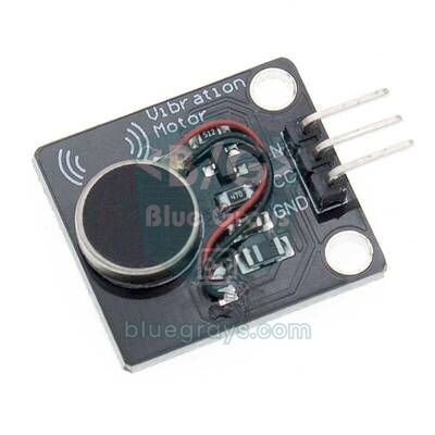
What is a vibration motor and how does it work?
ERM stands for "Eccentric Rotating Mass". The motor shaft carries a small mass whose centre of gravity is not exactly in the middle. As the motor spins, this unbalanced mass pulls the motor in one direction on every turn, and you feel that pull as vibration. In coin motors the mass spins inside the flat housing and nothing moves on the outside, which makes them very easy to stick in place and use. Cylinder ERM motors have a half-moon metal weight on the outside and vibrate more strongly. Both the strength and the frequency of the vibration depend on motor speed: as the voltage rises the motor speeds up, and the vibration gets both stronger and higher in pitch. The LRA (linear resonant actuator), increasingly used in phones and game controllers, works differently: it moves a magnet on a spring back and forth and only works properly with an alternating signal at its own resonant frequency, not with plain DC. The modules found in Arduino kits are almost always ERM.
| Feature | Typical coin ERM motor (e.g. 1027) |
|---|---|
| Size | 10 mm diameter, 2.7 mm thick |
| Rated voltage | 3 V (about 2.5–3.5 V) |
| Running current | About 60–90 mA at 3 V |
| Start-up current | Briefly 100–120 mA |
| Speed | About 10,000–13,000 rpm |
| Vibration frequency | About 160–220 Hz |
| Minimum start voltage | About 2–2.3 V; below that the motor will not start |
What is inside a vibration motor module?
An Arduino Uno pin can deliver at most 40 mA, and the safe limit is around 20 mA. ESP32 and Pico pins are weaker still. A vibration motor draws 60–120 mA and behaves like a coil: the moment its current is cut, a high reverse voltage spike appears across its terminals. That is why connecting the motor straight to a pin strains the pin and can reset or even damage the microcontroller. A ready-made module solves the problem with three parts:
- Driver transistor: Usually an S8050 or a similar small NPN transistor, on some modules an N-channel MOSFET. The Arduino pin supplies only a few milliamps of control current, and the motor current flows through the transistor. We explained how a transistor works as a switch in What Is a Transistor?.
- Base resistor: Limits the current from the pin to the transistor; a value of around 1 kΩ works with both 5 V and 3.3 V boards.
- Flyback diode: Connected in reverse across the motor, this diode short-circuits the voltage spike produced when the motor switches off and protects the transistor. You can read about its job in What Is a Diode?.
Most modules have three pins: VCC, GND and the signal pin IN (S or SIG on some boards). When you set IN HIGH, the transistor turns on and the motor spins. The module itself runs on 3.3–5 V. Powered from 5 V, the motor sees about 4.5 V after the small drop across the transistor, which is above the rating of a 3 V motor. That is fine for short alerts, but if the motor will run continuously for a long time, limiting the power to about 60–70 percent with PWM extends its life.
Wiring: Arduino Uno, ESP32 and Raspberry Pi Pico
The table below lists the pins used by all the sketches in this article. On every board the motor pin must be able to output PWM. On the ESP32 and Pico the 3.3 V signal going to the IN pin is enough to drive the transistor; you can connect the module's VCC pin to 5 V for stronger vibration or to 3.3 V for gentler vibration. Whichever supply you choose, the grounds must be common.
| Connection | Arduino Uno | ESP32 | Raspberry Pi Pico |
|---|---|---|---|
| Module VCC | 5V | VIN (5 V) or 3V3 | VBUS (5 V) or 3V3(OUT) |
| Module GND | GND | GND | GND |
| Module IN | D5 (PWM) | GPIO 25 | GP15 |
| Button (other leg to GND) | D2 | Touch pin GPIO 4 (T0) | GP14 |
| HC-SR04 TRIG (cane example) | D9 | - | - |
| HC-SR04 ECHO (cane example) | D10 | - | - |
First sketch: on/off and vibration strength with PWM
You can think of a vibration motor module like an LED: digitalWrite(HIGH) runs the motor at full power, while analogWrite() uses PWM to set the average voltage and therefore the strength of the vibration. On the Arduino Uno pins D5 and D6 run at about 980 Hz and the other PWM pins at about 490 Hz. We covered PWM basics in detail in What Is PWM?. ERM motors have an important trait: getting a stopped motor to start turning takes more power than keeping a spinning motor going. That is why a motor started with a low PWM value may not move at all. The solution is to start the motor at full power for a few tens of milliseconds and then drop to the value you want; this is called a kick-start. The sketch below first gives a short buzz at full power, then raises the strength step by step and prints each step to the Serial Monitor.
1const int MOTOR_PIN = 5;            // PWM pini (Uno'da ~980 Hz) / PWM pin (~980 Hz on Uno)
2
3// Kalkış darbesiyle istenen güce geç / start with a kick, then go to the requested power
4void motorGuc(int guc) {
5  static int oncekiGuc = 0;
6  if (guc > 0 && oncekiGuc == 0 && guc < 200) {
7    analogWrite(MOTOR_PIN, 255);    // durgun motoru tam güçle kaldır / kick a stopped motor at full power
8    delay(30);
9  }
10  analogWrite(MOTOR_PIN, guc);      // 0-255 arası güç / power between 0 and 255
11  oncekiGuc = guc;
12}
13
14void setup() {
15  Serial.begin(9600);
16  pinMode(MOTOR_PIN, OUTPUT);
17
18  motorGuc(255);                    // 300 ms tam güç / 300 ms at full power
19  delay(300);
20  motorGuc(0);
21  delay(1000);
22}
23
24void loop() {
25  for (int guc = 60; guc <= 255; guc += 15) {
26    Serial.print("PWM: ");
27    Serial.println(guc);
28    motorGuc(guc);
29    delay(700);
30    motorGuc(0);                    // her adım arasında dur / stop between steps
31    delay(500);
32  }
33  delay(2000);
34}
When you run the code you will notice that the motor does not vibrate at all, or only very weakly, below a certain PWM value. With a 5 V supply this threshold is usually between 70 and 110; the exact value depends on the motor and the module. Note the value in the Serial Monitor where you first clearly feel the motor and use it as the minimum power in your project. Thanks to the kick-start, values slightly below this threshold can also work, because once the motor is spinning it keeps turning with less power.
| PWM value (5 V supply) | Average voltage | Vibration you feel |
|---|---|---|
| 0–60 | 0–1.2 V | None, the motor does not turn |
| 70–110 | 1.4–2.2 V | Threshold zone; may need a kick-start |
| 120–170 | 2.4–3.3 V | Light to medium vibration, ideal for long alerts |
| 180–255 | 3.5–4.5 V | Strong vibration, for short, attention-grabbing alerts |
Haptic patterns: short tap, double tap, heartbeat and SOS
A single kind of vibration only says "something happened". Different patterns also tell the user what happened: a short tap can mean confirmation, two short taps a warning, a long buzz an alarm and a heartbeat-like rhythm a reminder. The human hand barely feels vibrations shorter than 20–30 ms, and an ERM motor needs about 30–50 ms to spin up. So keep the shortest buzz in a pattern at 40–60 ms and the gap between two buzzes at least 80–100 ms. In the sketch below each pattern is an array of {power, duration} pairs. The pattern player works with millis(), so loop() can do other jobs while a pattern is playing. Every press of the button on D2 plays the next pattern.
1const int MOTOR_PIN = 5;
2const int BUTON_PIN = 2;            // diğer ucu GND / other leg to GND
3
4struct Adim { uint8_t guc; uint16_t sure; };   // güç 0-255, süre ms / power 0-255, duration ms
5
6const Adim TIK[]       = {{255, 50}};
7const Adim CIFT_TIK[]  = {{255, 50}, {0, 100}, {255, 50}};
8const Adim UZUN[]      = {{200, 600}};
9const Adim KALP[]      = {{255, 60}, {0, 120}, {180, 80}, {0, 600}, {255, 60}, {0, 120}, {180, 80}};
10const Adim SOS[]       = {{255, 100}, {0, 100}, {255, 100}, {0, 100}, {255, 100}, {0, 300},
11                          {255, 350}, {0, 100}, {255, 350}, {0, 100}, {255, 350}, {0, 300},
12                          {255, 100}, {0, 100}, {255, 100}, {0, 100}, {255, 100}};
13const Adim ARTAN[]     = {{120, 150}, {160, 150}, {200, 150}, {255, 300}};
14
15struct Desen { const Adim *adimlar; uint8_t adet; const char *ad; };
16const Desen DESENLER[] = {
17  {TIK, 1, "Tik"}, {CIFT_TIK, 3, "Cift tik / Double tap"}, {UZUN, 1, "Uzun / Long"},
18  {KALP, 7, "Kalp atisi / Heartbeat"}, {SOS, 17, "SOS"}, {ARTAN, 4, "Artan / Ramp"}
19};
20const uint8_t DESEN_SAYISI = sizeof(DESENLER) / sizeof(DESENLER[0]);
21
22const Adim *calanDesen = nullptr;   // şu an çalan desen / pattern now playing
23uint8_t calanAdet = 0, adimNo = 0;
24unsigned long adimBaslangic = 0;
25
26void desenBaslat(const Desen &d) {
27  calanDesen = d.adimlar;
28  calanAdet = d.adet;
29  adimNo = 0;
30  adimBaslangic = millis();
31  analogWrite(MOTOR_PIN, calanDesen[0].guc);
32  Serial.println(d.ad);
33}
34
35void desenGuncelle() {              // loop'ta sürekli çağır / call it continuously in loop
36  if (calanDesen == nullptr) return;
37  if (millis() - adimBaslangic < calanDesen[adimNo].sure) return;
38  adimNo++;
39  if (adimNo >= calanAdet) {        // desen bitti / pattern finished
40    analogWrite(MOTOR_PIN, 0);
41    calanDesen = nullptr;
42    return;
43  }
44  adimBaslangic = millis();
45  analogWrite(MOTOR_PIN, calanDesen[adimNo].guc);
46}
47
48void setup() {
49  Serial.begin(9600);
50  pinMode(MOTOR_PIN, OUTPUT);
51  pinMode(BUTON_PIN, INPUT_PULLUP);
52}
53
54void loop() {
55  static uint8_t siradaki = 0;
56  static bool oncekiBasili = false;
57  bool basili = (digitalRead(BUTON_PIN) == LOW);
58  if (basili && !oncekiBasili && calanDesen == nullptr) {   // yeni basış / new press
59    desenBaslat(DESENLER[siradaki]);
60    siradaki = (siradaki + 1) % DESEN_SAYISI;
61  }
62  oncekiBasili = basili;
63  desenGuncelle();
64  delay(5);                         // basit ark önleme / simple debounce
65}
To change the patterns you only need to edit the arrays; the player function stays the same. In the SOS pattern the short buzzes are 100 ms, the long ones 350 ms and the gap between letters 300 ms; these proportions follow the "dot, dash" layout of Morse code. Keep patterns clearly different so users do not confuse them: use different counts (one, two, three buzzes) or clearly different durations. Before adding patterns to a project, try them on a few people and ask them to guess what each pattern means; in haptic design that is the best test.
Wearable alerts and the smart cane
A vibration motor shines where sound is annoying or cannot be heard. In wearable projects place the motor inside a wristband, glove or belt, close to the skin. The inside of the wrist, the palm and the fingertips are the areas most sensitive to vibration. Sticking the motor to a hard surface, for example the inner wall of a 3D-printed case with double-sided tape, transmits the vibration better than stitching it loosely to fabric. In smart cane projects for visually impaired people, the motor goes in the part of the handle right under the thumb, and the distance to an obstacle is turned into the rate and strength of the vibration: as the obstacle gets closer the buzzes come faster and stronger, turning into continuous vibration when it is very close. The sketch below shows this logic with an HC-SR04 distance sensor.
1const int TRIG_PIN  = 9;
2const int ECHO_PIN  = 10;
3const int MOTOR_PIN = 5;
4const int UZAK_CM   = 150;          // bunun ötesinde titreşim yok / no vibration beyond this
5const int YAKIN_CM  = 30;           // bunun altında sürekli titreşim / continuous below this
6
7int mesafeOlc() {
8  digitalWrite(TRIG_PIN, LOW);
9  delayMicroseconds(2);
10  digitalWrite(TRIG_PIN, HIGH);
11  delayMicroseconds(10);
12  digitalWrite(TRIG_PIN, LOW);
13  unsigned long sure = pulseIn(ECHO_PIN, HIGH, 12000);   // ~2 m zaman aşımı / ~2 m timeout
14  if (sure == 0) return 999;                              // yankı yok / no echo
15  return sure / 58;                                       // cm
16}
17
18void setup() {
19  pinMode(TRIG_PIN, OUTPUT);
20  pinMode(ECHO_PIN, INPUT);
21  pinMode(MOTOR_PIN, OUTPUT);
22}
23
24void loop() {
25  int cm = mesafeOlc();
26  if (cm > UZAK_CM) {
27    analogWrite(MOTOR_PIN, 0);               // yol açık / path is clear
28    delay(60);
29  } else if (cm <= YAKIN_CM) {
30    analogWrite(MOTOR_PIN, 255);             // dur uyarısı / stop warning
31    delay(60);
32  } else {
33    int guc   = map(cm, UZAK_CM, YAKIN_CM, 150, 255);   // yaklaştıkça güçlenir / stronger when closer
34    int bosluk = map(cm, UZAK_CM, YAKIN_CM, 900, 150);  // yaklaştıkça sıklaşır / more frequent when closer
35    analogWrite(MOTOR_PIN, guc);
36    delay(80);                               // 80 ms titreşim / 80 ms buzz
37    analogWrite(MOTOR_PIN, 0);
38    delay(bosluk);
39  }
40}
To keep things simple this sketch uses delay() and does not take new readings while it waits; in a real cane, a millis()-based structure like the one in the previous section responds better. We keep the minimum power at 150 so that the motor does not stay below its threshold and fail to turn for distant obstacles. For a complete project with puddle warning, fall detection, SOS and battery calculations, see the Smart Cane Arduino Project, and for sensor details the HC-SR04 distance sensor guide.
Current, power supply and battery life
A coin motor draws 60–90 mA while running and briefly more than 100 mA at start-up. That is something the Arduino Uno's 5V pin can easily supply from USB. Problems usually appear in battery-powered circuits whose voltage is already marginal, or in projects with several motors running at once: as the motor starts, the voltage dips for a moment and the board resets. To prevent this, add a 47–100 µF electrolytic capacitor between the module's VCC and GND pins, and if you use more than one motor, start them a few milliseconds apart rather than at the same moment. When calculating battery life, remember that the motor runs in short bursts, not continuously: for example, an 80 mA motor that runs for a total of 3 seconds per minute has an average current of only 4 mA. Use the Battery Life tool with your own project's values to find out how many hours it will last.
Touch feedback with the ESP32
Two ESP32 advantages combine very well with a vibration motor: the chip has capacitive touch pins, and the LEDC unit that generates PWM lets you set the frequency freely. The sketch below gives a short "click" buzz, like a phone screen, when a wire or piece of copper foil connected to GPIO 4 (T0) is touched; if the touch lasts more than 1 second it confirms with a long buzz. We set the PWM frequency to 20 kHz, which is at the limit of human hearing, so any faint whine from the motor driver also disappears. The code compiles with both the 2.x and 3.x versions of the ESP32 Arduino core, because the LEDC function names differ between the two.
1const int MOTOR_PIN   = 25;         // modül IN / module IN
2const int DOKUNMA_PIN = T0;         // GPIO 4, kapasitif dokunma / capacitive touch
3const int PWM_FREKANS = 20000;      // 20 kHz, duyulmaz / 20 kHz, inaudible
4const int PWM_BIT     = 8;          // 0-255 çözünürlük / 0-255 resolution
5const int PWM_KANAL   = 0;          // yalnız 2.x için / only for core 2.x
6
7void motorYaz(uint8_t guc) {
8#if ESP_ARDUINO_VERSION_MAJOR >= 3
9  ledcWrite(MOTOR_PIN, guc);        // 3.x: pin numarasıyla / 3.x: by pin number
10#else
11  ledcWrite(PWM_KANAL, guc);        // 2.x: kanal numarasıyla / 2.x: by channel number
12#endif
13}
14
15void titret(uint8_t guc, int ms) {
16  motorYaz(guc);
17  delay(ms);
18  motorYaz(0);
19}
20
21int esik = 0;
22
23void setup() {
24  Serial.begin(115200);
25#if ESP_ARDUINO_VERSION_MAJOR >= 3
26  ledcAttach(MOTOR_PIN, PWM_FREKANS, PWM_BIT);
27#else
28  ledcSetup(PWM_KANAL, PWM_FREKANS, PWM_BIT);
29  ledcAttachPin(MOTOR_PIN, PWM_KANAL);
30#endif
31  long toplam = 0;                  // dokunulmamış değeri ölç / measure the untouched value
32  for (int i = 0; i < 20; i++) {
33    toplam += touchRead(DOKUNMA_PIN);
34    delay(10);
35  }
36  esik = (toplam / 20) * 7 / 10;    // %70'inin altı dokunuş / below 70% means touched
37  Serial.printf("Dokunma esigi / Touch threshold: %d\n", esik);
38  titret(255, 60);                  // hazır işareti / ready signal
39}
40
41void loop() {
42  static bool dokunuyor = false;
43  static unsigned long dokunmaBasi = 0;
44  static bool uzunVerildi = false;
45  int deger = touchRead(DOKUNMA_PIN);   // dokununca değer düşer / value drops when touched
46
47  if (deger < esik && !dokunuyor) {     // dokunuş başladı / touch started
48    dokunuyor = true;
49    uzunVerildi = false;
50    dokunmaBasi = millis();
51    titret(255, 40);                    // kısa tık / short click
52  } else if (deger < esik && !uzunVerildi && millis() - dokunmaBasi > 1000) {
53    titret(200, 400);                   // uzun basış onayı / long-press confirmation
54    uzunVerildi = true;
55  } else if (deger >= esik) {
56    dokunuyor = false;
57  }
58  delay(20);
59}
On the ESP32 the touch pin value is usually around 50–80 when untouched and drops clearly when touched by a finger; that is why the code measures the average value at start-up and calculates the threshold automatically. On the ESP32-S2 and S3, however, touch values go the other way and rise when touched; on those boards you need to reverse the comparison. If you connect the module's VCC pin to the ESP32's VIN pin, the motor vibrates more strongly on 5 V; the 3.3 V signal on the IN pin is enough to drive the transistor. By combining this with Wi-Fi or Bluetooth you can build a wristband that buzzes when your phone gets a notification, or an alert device controlled over ESP32 BLE.
Vibration motor with the Raspberry Pi Pico and MicroPython
On the Raspberry Pi Pico every GPIO pin can generate PWM. In MicroPython the duty_u16() function of the PWM class takes a value between 0 and 65535; 65535 means full power. The code below plays a heartbeat pattern each time the button on GP14 is pressed. As in the Arduino example, the pattern is a list of power and duration pairs. You can connect the module's VCC pin to VBUS (the USB 5 V) for stronger vibration or to 3V3(OUT) for gentler vibration.
1from machine import Pin, PWM
2import time
3
4motor = PWM(Pin(15))                   # modül IN pini / module IN pin
5motor.freq(1000)                       # 1 kHz PWM
6buton = Pin(14, Pin.IN, Pin.PULL_UP)   # diğer ucu GND / other leg to GND
7
8# (güç %, süre ms) çiftleri / (power %, duration ms) pairs
9KALP = [(100, 60), (0, 120), (70, 80), (0, 600), (100, 60), (0, 120), (70, 80)]
10CIFT_TIK = [(100, 50), (0, 100), (100, 50)]
11
12def guc_ayarla(yuzde):
13    motor.duty_u16(int(65535 * yuzde / 100))
14
15def desen_cal(desen):
16    for yuzde, sure in desen:
17        guc_ayarla(yuzde)
18        time.sleep_ms(sure)
19    guc_ayarla(0)                      # her zaman kapalı bitir / always end switched off
20
21desen_cal(CIFT_TIK)                    # açılış işareti / start-up signal
22while True:
23    if buton.value() == 0:             # basıldı / pressed
24        desen_cal(KALP)
25        while buton.value() == 0:      # bırakılmasını bekle / wait for release
26            time.sleep_ms(10)
27    time.sleep_ms(20)
The Pico's pins work at 3.3 V and drawing more than about 12 mA from a single pin is not recommended, so with the Pico too you should use the transistor module, not a bare motor. The button is not read while a pattern plays; if you need to do several things at once, you can build the Arduino millis() pattern with time.ticks_ms() or advance the pattern steps with a Timer interrupt. If you are just starting with MicroPython, the MicroPython basics article is a good place to begin.
DRV2605 haptic driver: professional vibration effects
A transistor module only switches the motor on and off or makes it stronger or weaker with PWM. The crisp "click" you feel on a phone comes from starting and stopping the motor very quickly: the motor is first accelerated with a pulse above its rated voltage (overdrive), and when the vibration ends it is braked with a short reverse voltage. Texas Instruments' DRV2605L chip does this by itself. It connects over I2C (address 0x5A), can drive both ERM and LRA motors and contains 123 built-in effects such as clicks, double clicks, buzzes and soft bumps. It learns the motor's characteristics through auto-calibration and can turn an audio input into vibration. With the Adafruit DRV2605 library it takes only a few lines; on the Uno you connect SDA to A4 and SCL to A5, and the motor plugs straight into the DRV2605 board's motor output.
1#include <Wire.h>
2#include <Adafruit_DRV2605.h>
3
4Adafruit_DRV2605 haptik;
5
6void setup() {
7  Serial.begin(9600);
8  if (!haptik.begin()) {               // I2C adresi 0x5A / I2C address 0x5A
9    Serial.println("DRV2605 bulunamadi / not found");
10    while (1) {}
11  }
12  haptik.selectLibrary(1);             // ERM efekt kütüphanesi / ERM effect library
13  haptik.setMode(DRV2605_MODE_INTTRIG); // go() ile tetikle / trigger with go()
14}
15
16void efektCal(uint8_t efekt) {
17  haptik.setWaveform(0, efekt);        // 1. slot: efekt / slot 1: effect
18  haptik.setWaveform(1, 0);            // 0 = dizinin sonu / 0 = end of sequence
19  haptik.go();
20}
21
22void loop() {
23  efektCal(1);                         // 1: güçlü tık / strong click
24  delay(1000);
25  efektCal(10);                        // 10: çift tık / double click
26  delay(1000);
27  efektCal(14);                        // 14: güçlü vızıltı / strong buzz
28  delay(2000);
29}
The DRV2605 can play up to 8 effects in a row in one sequence; you fill slots 0 to 7 with setWaveform() and mark the end of the sequence with 0. If you use an LRA motor, call useLRA() and select LRA library number 6. For simple alerts a transistor module is more than enough; if you are designing a wearable product, a game controller or a touch interface, the DRV2605 noticeably improves the feel.
Project ideas with a vibration motor
- Silent timer wristband: Build a pomodoro timer that buzzes on your wrist when the lesson or study session ends, without disturbing the class.
- Smart cane for visually impaired people: Follow the smart cane guide for a complete project that turns obstacle distance into a vibration rhythm.
- Silent doorbell: Make a device in your pocket buzz when a PIR motion sensor at the door detects someone.
- Game controller: Add rumble on collisions to a game controller built with a joystick module.
- Posture reminder: Measure your back angle with an MPU6050 and give a short buzz when you sit hunched for too long.
- Vibration instead of sound: In an alarm used at night, put a vibration motor under the pillow instead of a buzzer.
Common mistakes and fixes
| Symptom | Likely cause | Fix |
|---|---|---|
| The motor does not turn at all | PWM value below the start threshold or no common GND | Try 255 first, add a kick-start and join the grounds |
| The Arduino resets when the motor runs | Start-up current collapses the supply or there is no diode | Use a ready-made module and add a 47–100 µF capacitor between VCC and GND |
| The vibration is very weak | The module runs on 3.3 V or the motor sits on a soft surface | Connect VCC to 5 V and stick the motor to a hard surface |
| The motor gets warm | It runs at full power on 5 V for a long time | Limit power to 60–70% with PWM and use short pulses instead of continuous vibration |
| A faint whine comes from the motor | The PWM frequency is in the audible range | Set the LEDC frequency to 20 kHz on the ESP32; use short buzzes on the Uno |
| ledcSetup not found error on the ESP32 | ESP32 core version 3.x | Use the #if ESP_ARDUINO_VERSION_MAJOR switch from this article |
| A pin stopped working after connecting a bare motor | The motor was connected straight to the pin and damaged it | Use another pin and always drive the motor through a transistor and diode |
| The patterns feel alike | The buzzes are too short or the gaps too narrow | Make the shortest buzz 40–60 ms and the gap at least 100 ms |
A vibration motor is the cheapest way to add the sense of touch to your projects alongside screens and sounds. Now that you know about the transistor and diode inside the module, setting strength with PWM, the kick-start and haptic patterns, you can design both silent alerts and assistive devices for visually impaired people. In the BlueGrays app you can explore projects such as a buzzer, an HC-SR04 parking sensor and PWM power control with step-by-step circuit diagrams and ready-to-use code, and develop your own ideas by adding a vibration motor to them.
Frequently asked questions
How do I connect a vibration motor to an Arduino?
Connect the ready-made vibration motor module's VCC pin to 5V, GND to GND and IN to a PWM pin such as D5. The transistor on the module carries the motor current and the diode protects the Arduino. If you use a bare motor, you must add an NPN transistor, a 1 kΩ base resistor and a diode.
What voltage does a vibration motor run on?
Most coin-type ERM vibration motors are rated at 3 V and work between about 2.5 and 3.5 V. Ready-made modules can be powered from 3.3–5 V; at 5 V the motor vibrates more strongly, but limiting the power with PWM in long use extends its life. Below about 2 V the motor will not start.
How much current does a vibration motor draw?
A typical coin vibration motor draws 60–90 mA while running and briefly 100–120 mA at start-up. That is several times the current an Arduino pin can safely supply. So the motor should be driven through a transistor or a ready-made module.
How do I control the strength of a vibration motor?
Strength is set with PWM, that is with analogWrite(pin, 0–255) on the Arduino; the higher the value, the faster the motor spins and the stronger it vibrates. Because the motor does not turn below a certain threshold, giving full power for 20–30 ms first and then dropping to the target value works well at low power. On the ESP32 ledcWrite() and on the Pico duty_u16() do the same job.
What is the difference between ERM and LRA vibration motors?
An ERM motor vibrates by spinning an unbalanced mass on its shaft and runs on plain DC. An LRA moves a magnet on a spring back and forth, only works with an alternating signal at its resonant frequency and responds more crisply and quickly. Driving an LRA needs a haptic driver such as the DRV2605.
Why does a vibration motor need a diode?
Because the motor contains a coil, a high reverse voltage spike appears across its terminals the moment its current is cut. A diode connected in reverse across the motor short-circuits this spike and keeps the transistor and the microcontroller from being damaged. Ready-made modules already have this diode on the board.
Projects to build after reading this
See all projects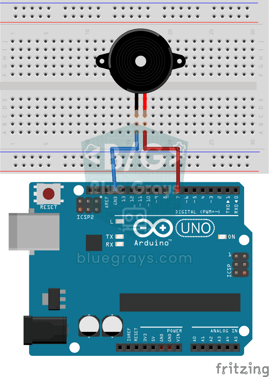
Using a Buzzer
Ever wondered how a doorbell or an alarm makes its sound? The Arduino makes a small buzzer beep at short intervals: beep, pause, beep, pause.
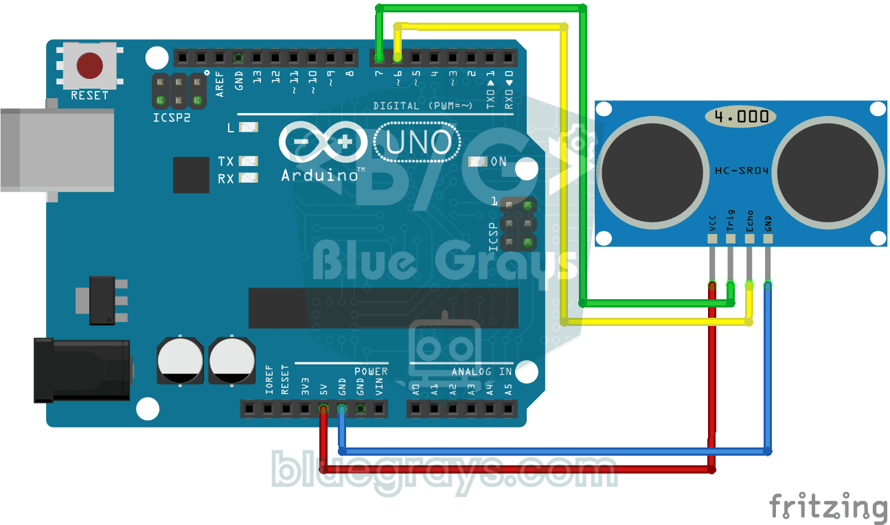
HC-SR04 Distance Measurement (Serial Display)
The HC-SR04 sensor works just like a bat finding its way in the dark: it sends out a sound you cannot hear, listens for the echo and measures how far away the object in front of it is.

LED Control with a Push Button (Push)
Just like a doorbell: the light stays on as long as you press, and goes off when you let go.
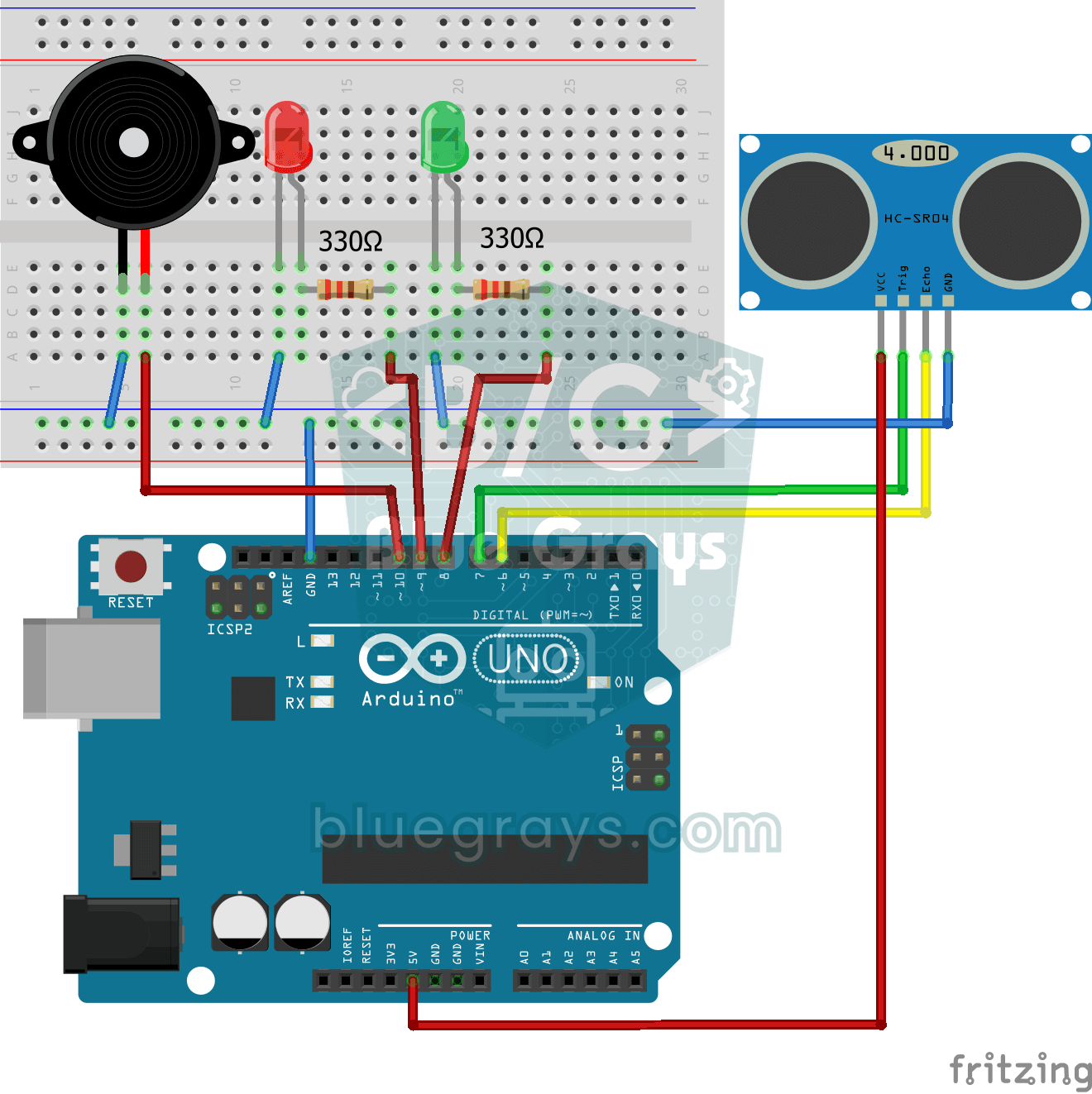
Parking Sensor with HC-SR04
A mini version of a car's parking sensor: the closer something gets, the faster the beeps.

ESP32 LED Fade with PWM
Smoothly changing the brightness of the LED from 0 to max, from max to 0. We control PWM with analogWrite() as in Arduino - the same syntax as ESP32 Arduino Core 3.0+ works without problems. Pin definition + pinMode + analogWrite is enough.

ESP32 LED Brightness Control with a Potentiometer (Analog → PWM)
In this project, we control the brightness of an LED analogically using a potentiometer. The ESP32's ADC pin reads the 0-3.3V voltage from the potentiometer, and this value is then converted into a PWM (Pulse Width Modulation) signal and sent to the LED. As a result, as you turn the potentiometer, the LED gradually brightens and dims. With Arduino Core 3.0+, analogWrite() can be used directly; on the ESP32-S2/S3, the ADC resolution is fixed at 12-bit.

ESP32 Parking Sensor (HC-SR04 + 5-LED Bar + Buzzer + OLED)
The ESP32 version of a car parking sensor! The HC-SR04 ultrasonic sensor measures the distance to the object in front. As it gets closer, a 5-LED bar fills up (green → yellow → red) and the buzzer beeps faster. Very close (under 10 cm), a continuous alarm sounds and all LEDs light up. The SSD1306 OLED display shows the live distance in cm in large text, plus a status message.
Raspberry Pi Pico PWM LED Fade (Breathing Effect)
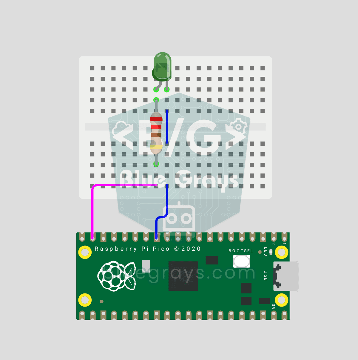
The LED doesn't just blink anymore, it breathes! With the Raspberry Pi Pico's PWM (Pulse Width Modulation), the LED's brightness slowly rises and then slowly fades, a calm "breathing" effect like a sleeping laptop's light. You'll learn the machine.PWM class, the 16-bit brightness value from 0–65535 with duty_u16() and the PWM frequency.