
TP4056 Wiring Guide: 18650 Charger Module, Protection and ESP32
How to wire a TP4056 charger: B+/B- and OUT+/OUT- pins, protected DW01 version, LED meanings, Rprog current setting, 5 V via MT3608 and ESP32 battery reading.
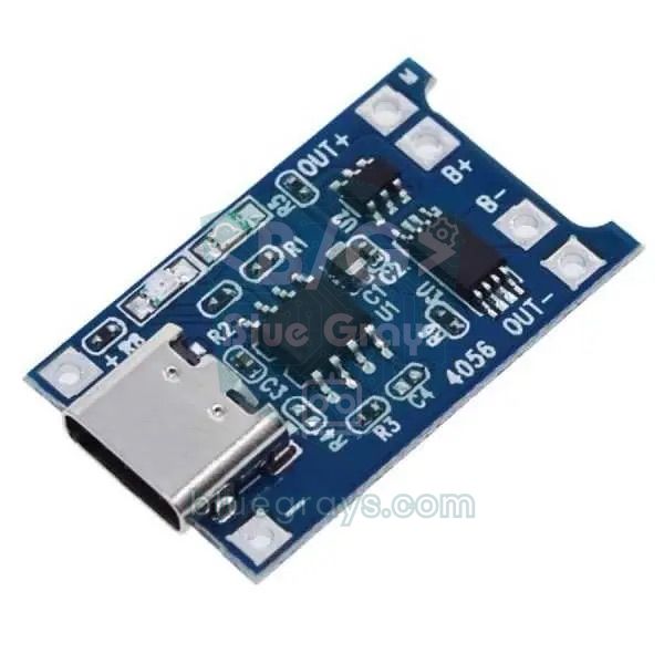
TP4056 wiring is the cheapest way to charge a single-cell 18650 or LiPo battery safely from USB and run an Arduino, ESP32 or Raspberry Pi Pico project from that same battery: the USB cable goes into the module's input, the battery goes to B+ and B-, and on protected modules your circuit goes to OUT+ and OUT-. The module charges the battery up to 4.2 V using the constant-current/constant-voltage method, stops on its own when the battery is full and shows its status with two LEDs. This fingernail-sized board is the heart of projects that run away from a wall socket, such as portable weather stations, robots, rechargeable lamps and wireless sensors.
But this cheap module has a few traps: the protected and unprotected versions are wired differently, the default 1 A charge current is too much for small batteries, powering your circuit while charging can stop the charge from ever finishing, and two cells in series can never be charged with this module. In this guide you'll learn, step by step, what each pin does, what the LEDs mean, how to set the charge current with the Rprog resistor, how to add an MT3608 boost module for boards that need 5 V, and how to measure the battery voltage with an ESP32 and turn it into a percentage.
What is the TP4056 and how does it work?
The TP4056 is a linear charger IC made for single-cell lithium-ion (Li-ion) and lithium-polymer (LiPo) batteries. Lithium batteries can't be filled with just any adapter; they need a specific charging profile, and the TP4056 applies it all by itself. If the battery is below 2.9 V, it first charges gently in the pre-charge (trickle) phase at about a tenth of the set current, roughly 130 mA with the 1 A setting. Once the voltage passes 2.9 V, it switches to the constant current (CC) phase and delivers the full set current. When the battery reaches 4.2 V, the constant voltage (CV) phase begins: the voltage is held at 4.2 V and the current slowly drops. Charging ends when the current falls to a tenth of the set value (100 mA with the 1 A setting). If the battery later drops to about 4.05 V, the module restarts charging automatically. If the chip gets very hot, it reduces the charge current by itself, so it's normal for the module to be warm while charging.
| Feature | Value |
|---|---|
| Input voltage | 4.0–8 V (5 V recommended; micro USB or USB-C) |
| Charge termination voltage | 4.2 V (±1.5%) |
| Charge current | Up to 1 A; 1 A by default on modules (Rprog = 1.2 kΩ) |
| Pre-charge | About 1/10 of the set current below 2.9 V |
| Charge termination | When the current drops to 1/10 of the set value (C/10) |
| Recharge | Automatic when the battery drops to about 4.05 V |
| Status outputs | CHRG (charging) and STDBY (full) LEDs |
| Suitable batteries | Single-cell (1S) 3.7 V Li-ion and LiPo only; not LiFePO4 |
Protected (DW01) vs unprotected TP4056 modules
Two different boards are sold under the same name. The unprotected module has only the TP4056 chip and four connection points: IN+/IN- and BAT+/BAT-. It charges the battery but supervises nothing while the battery discharges. The protected module adds a DW01A protection IC and an 8205A dual MOSFET, and it has six pads: IN+/IN-, B+/B- and OUT+/OUT-. The protection circuit sits like a switch between the battery's negative terminal and your circuit's negative terminal (OUT-). When the battery is over-discharged or overcharged, when the circuit draws too much current, or when the output is shorted, it opens this switch and disconnects the battery from the circuit.
| Feature | Unprotected module | Protected module (DW01A + 8205A) |
|---|---|---|
| Pads | IN+, IN-, BAT+, BAT- | IN+, IN-, B+, B-, OUT+, OUT- |
| Overcharge protection | Only the TP4056's 4.2 V limit | Also cuts off at about 4.25–4.3 V |
| Over-discharge protection | None | Cuts off at about 2.4 V, releases around 3.0 V |
| Overcurrent and short circuit | None | Cuts off at about 3 A and on a short circuit |
| When to choose it | If the battery has its own protection circuit | With bare, unprotected cells, i.e. in almost every project |
18650 battery: the voltages you need to know
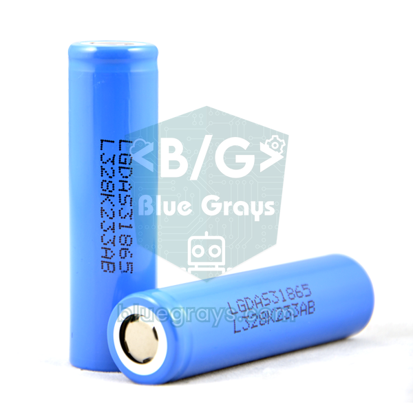
The name 18650 comes from the cell's size: 18 mm in diameter and 65 mm long. Its nominal voltage is 3.6–3.7 V, but that's an average; a full cell sits at 4.2 V and an empty one at around 3.0 V. Real capacities range from 2000 to 3500 mAh; cells labelled 6800 or 9900 mAh are fakes and often don't deliver even 1000 mAh. Protected 18650s with their own protection circuit are a few millimetres longer and may not fit every holder. You can work out how long your project will run on one battery with the Battery Life Calculator, and read about capacity units in mAh and Wh explained.
| State | Voltage | Notes |
|---|---|---|
| Fully charged | 4.20 V | The TP4056 ends charging here |
| Nominal | 3.6–3.7 V | The value on the label, the average working voltage |
| Considered empty | 3.0–3.3 V | Stopping your project here extends battery life |
| Protection cut-off | 2.4–2.5 V | The DW01A turns off the output; try not to go this low |
| Danger zone | Below 2.0 V | Don't charge a cell that has sat this low for long; replace it |
TP4056 wiring: the IN, B+/B- and OUT+/OUT- pins
| Pad | Connects to | Notes |
|---|---|---|
| USB input | 5 V adapter or computer | Micro USB or USB-C; the easiest way |
| IN+ / IN- | Plus and minus of an external 5 V source | For soldered power instead of USB; don't use both at once |
| B+ / B- | Plus and minus of the 18650 battery | Only the battery goes here |
| OUT+ / OUT- | Plus and minus of your circuit (the load) | On a protected module the load always goes here |
| BAT+ / BAT- (unprotected) | Battery and load together | No protection; the load goes in parallel with the battery |
- Solder the red wire of the battery holder to B+ and the black wire to B-. Don't put the battery in yet.
- Solder your circuit's positive supply wire to OUT+ and its negative (GND) wire to OUT-. If you're powering a board that needs 5 V, an MT3608 boost module goes in between.
- Check the solder joints and use a multimeter to make sure there's no short between B+ and B-.
- Insert the battery, minding the polarity. On some protected modules the output may be off at first; plugging in USB once resets the protection and turns the output on.
- Plug in the USB cable: if the red LED lights up, charging has started. When the battery is full, the red LED goes out and the blue or green LED comes on.
- Once your multimeter shows the battery voltage (3.0–4.2 V) between OUT+ and OUT-, you can switch your circuit on.
What do the TP4056 LEDs mean?
| Red LED (CHRG) | Blue or green LED (STDBY) | Meaning |
|---|---|---|
| On | Off | Charging |
| Off | On | Charging complete (4.2 V) |
| Blinking or flickering | On | No battery inserted or a bad contact |
| Off | Off | Input below 4 V or no USB power |
| On for hours | Off | The load is preventing termination, or the battery is worn out |
With no battery inserted, it's normal for the blue LED to be on and the red one to flicker: the module keeps charging and discharging the capacitor on the empty battery terminal. You can roughly estimate charging time with capacity / current × 1.2. A 2600 mAh cell charges in about 3 hours at 1 A; because the current gradually drops in the final stage, it takes a little longer than the simple division suggests.
Setting the charge current: the Rprog resistor
The charge current is set by a single resistor between the TP4056's PROG pin (pin 2) and GND. On most modules this resistor is marked R3 and carries the code 122, meaning 1.2 kΩ, which gives 1 A. To decode markings like this you can use the SMD Code Decoder. The formula is approximately I (mA) = 1200 / Rprog (kΩ). To change the current, desolder the SMD resistor and solder in the value you want; if you can't find an SMD resistor of the right size, you can also solder a small through-hole resistor across the two pads.
| Rprog | Charge current | Suitable battery |
|---|---|---|
| 10 kΩ | 130 mA | 200–300 mAh small LiPo |
| 5 kΩ | 250 mA | 300–500 mAh LiPo |
| 4 kΩ | 300 mA | 500–600 mAh LiPo |
| 3 kΩ | 400 mA | Around 800 mAh |
| 2 kΩ | 580 mA | 1000–1200 mAh |
| 1.5 kΩ | 780 mA | 1500 mAh and above |
| 1.2 kΩ | 1000 mA | 18650 of 2000 mAh and above (module default) |
The general rule is to keep the charge current at around half the battery capacity (0.5C): 250 mA suits a 500 mAh LiPo and 1 A suits a 2600 mAh 18650. Take heat into account too: because the TP4056 is linear, the voltage difference between the input and the battery turns into heat. Charging a 3.6 V cell at 1 A from a 5 V input, the chip dissipates (5 − 3.6) × 1 = 1.4 W; that's why the module gets very hot and may throttle the current itself. You can also do power calculations like this with the Ohm's Law Calculator. A computer's USB 2.0 port only supplies 500 mA, so if you'll often charge from a computer, it makes sense to lower the current to around 500 mA.
Powering your circuit while charging (load sharing)
If you want your project to keep running while USB is plugged in, the simplest approach is to leave the circuit connected to OUT+ and OUT-; the TP4056 then charges the battery and powers the circuit at the same time. But the chip can't tell the current going into the battery from the current going to the circuit. If your circuit constantly draws more than 100 mA, the total current never drops below the termination threshold, charging never ends and the battery is held at 4.2 V for hours, which shortens its life. If your circuit draws close to 1 A, the battery won't even fill up. With an ESP32 in deep sleep or small circuits drawing a few mA, a direct connection causes no real trouble in practice; for always-on Wi-Fi projects, motors and LED strips, build a load sharing circuit.
| Part | Connection | Purpose |
|---|---|---|
| Schottky diode (1N5817, SS14) | Anode to USB 5 V (IN+), cathode to the circuit's positive input | Powers the circuit directly when USB is present |
| P-channel MOSFET (AO3401, DMG2305) | Drain to the battery (OUT+), source to the circuit's positive input | Connects the battery to the circuit when there's no USB |
| MOSFET gate connection | Directly to USB 5 V (IN+) | With USB plugged in, the MOSFET stays off and the battery only charges |
| 100 kΩ resistor | Between the MOSFET gate and GND | Pulls the gate to 0 V when USB is unplugged, turning the MOSFET on |
Need 5 V? Adding an MT3608 boost module
An 18650's voltage wanders between 3.0 and 4.2 V; that's not enough for an Arduino Uno, relay modules, servo motors or WS2812B LEDs that want 5 V. The fix is a boost (step-up) converter that raises the voltage. The most common is the MT3608 module: it gives an adjustable output of up to 28 V from a 2–24 V input, switches at 1.2 MHz and its internal switch has a 4 A current limit. In practice you can safely draw around 0.5–1 A at 5 V from a single 18650; beyond that the module heats up and efficiency drops. When you need to lower a voltage instead, you use the LM2596 buck module, which does the exact opposite.
- Connect the MT3608's VIN+ and VIN- inputs to the TP4056's OUT+ and OUT-.
- Without connecting anything to the output yet, connect your multimeter between VOUT+ and VOUT-.
- Turn the blue trimpot with a small screwdriver to set the output to 5.0–5.1 V. The trimpot is multi-turn, so the voltage may only start changing after several turns; keep turning patiently.
- Once it's set, connect your board's 5V pin to VOUT+ and its GND pin to VOUT-.
- Measure the voltage again while the circuit is running; if it drops below 4.8 V under load, shorten the wires or reduce the current draw.
| Board | How to power it from one 18650 | Notes |
|---|---|---|
| Arduino Uno / Nano | 5.0 V from the MT3608 → 5V pin | The 5V pin bypasses the regulator; never exceed 5.5 V |
| Arduino Pro Mini 3.3 V (8 MHz) | OUT+ directly to the RAW pin | Its low-dropout regulator can run from the battery voltage |
| ESP32 DevKit | 5 V from the MT3608 → VIN (5V) pin | The on-board AMS1117 drops about 1 V; don't connect the battery directly |
| Raspberry Pi Pico | OUT+ → Schottky diode → VSYS (pin 39) | VSYS accepts 1.8–5.5 V; no boost needed |
| SIM800L GSM module | OUT+ and OUT- directly | Needs 3.4–4.4 V; ideal for Li-ion |
If you plug the board into USB to upload code while the boost output is still connected, you're tying two power sources together. The safest approach is to disconnect the boost output while uploading. You'll find in detail which pin powers an Arduino, and how, in How to Power an Arduino.
Series cells can't be charged with a TP4056
The TP4056 only charges a single cell (1S) up to 4.2 V. A two-cell series 18650 pack (2S), common in robot cars, is 7.4 V nominal and 8.4 V when full; connect it to a single TP4056 and it won't charge, and the module and cells may be damaged. Fitting a separate TP4056 to each cell doesn't work either: the modules' negative inputs join at the same USB supply, and because the upper module's negative sits on the lower cell's positive, the lower cell is short-circuited. Since its end voltage is fixed at 4.2 V, the TP4056 isn't used with LiFePO4 cells either, whose charge must stop at 3.6 V.
- Connect in parallel (1S2P): With two cells in parallel the voltage stays at 3.7 V, the capacity doubles and you can charge them with a TP4056. Make sure the cells are at the same voltage before joining them.
- Boost it: If you need 7–12 V, step up the output of the parallel cells with an MT3608.
- Use a 2S charging circuit: A series pack needs an 8.4 V CC/CV charger and a balancing 2S BMS board.
- Take the cells out to charge: You can remove the cells of a series pack from their holder and charge them one by one in a separate 18650 charger.
Measuring battery voltage: voltage divider wiring
To know how full the battery is, measuring its voltage is enough. But a 4.2 V battery can't go straight into an ESP32 or Pico analog pin, because their ADC inputs handle 3.3 V at most. The fix is a voltage divider made of two equal resistors: 100 kΩ + 100 kΩ brings 4.2 V down to 2.1 V and draws only 21 µA from the battery. You can calculate the values with the Voltage Divider Calculator and read how the circuit works in The Voltage Divider Circuit. Adding a 100 nF capacitor between the measuring point and GND noticeably steadies readings taken through high-value resistors.
| Connection | Arduino Uno | ESP32 | Raspberry Pi Pico |
|---|---|---|---|
| Top resistor (100 kΩ) | OUT+ → midpoint | OUT+ → midpoint | OUT+ → midpoint |
| Bottom resistor (100 kΩ) | Midpoint → GND | Midpoint → GND | Midpoint → GND |
| Midpoint (measurement) | A0 | GPIO 34 (ADC1) | GP26 (ADC0) |
| 100 nF capacitor | Optional | Midpoint → GND | Midpoint → GND |
| TP4056 OUT- | GND | GND | GND |
| ADC range | 0–5 V, 10-bit | About 0–3.1 V, 12-bit | 0–3.3 V, 12-bit |
The Arduino Uno's ADC uses a 5 V reference; thanks to the divider, a 4.2 V battery appears as 2.1 V on A0 and the 10-bit reading gives a value between 0 and 1023. When the board is powered from USB or a boost module, the 5V pin may not be exactly 5.00 V; measure it with a multimeter and enter it as VREF in the code, and accuracy improves noticeably.
1// Arduino Uno: 18650 pil voltajı, A0'da 100k + 100k bölücü / battery voltage, 100k + 100k divider on A0
2const float VREF = 5.0;      // 5V pinini multimetreyle ölçüp yaz / measure the 5V pin and enter it
3const float DIVIDER = 2.0;   // bölücü oranı / divider ratio
4
5void setup() {
6  Serial.begin(9600);
7}
8
9void loop() {
10  long sum = 0;
11  for (int i = 0; i < 16; i++) {      // 16 ölçümün ortalaması / average of 16 readings
12    sum += analogRead(A0);            // 0-1023
13    delay(2);
14  }
15  float v = (sum / 16.0) * VREF / 1024.0 * DIVIDER;
16  Serial.print(F("Pil / Battery: "));
17  Serial.print(v, 2);
18  Serial.println(F(" V"));
19  if (v < 3.3) Serial.println(F("Pil zayif / Battery low"));
20  delay(1000);
21}
Measuring battery voltage and showing a percentage with the ESP32
The ESP32's ADC isn't perfectly linear and varies from board to board. That's why, instead of raw analogRead, it's more accurate to use analogReadMilliVolts, which applies the chip's factory calibration and returns millivolts directly. The code below averages 16 readings, multiplies by the divider ratio to get the battery voltage, converts it to a percentage using a table and, if the battery falls below 3.3 V, sends the ESP32 into deep sleep for 10 minutes.
1// TP4056 + 18650: ESP32 ile pil voltajı ve yüzdesi / battery voltage and percentage with ESP32
2const int BAT_PIN = 34;          // ADC1 pini, Wi-Fi açıkken de çalışır / ADC1 pin, works with Wi-Fi on
3const float DIVIDER = 2.0;       // 100k + 100k bölücü: pil / 2 / 100k + 100k divider: battery / 2
4const float LOW_BAT = 3.30;      // bu değerin altında uykuya geç / go to sleep below this voltage
5
6// Yaklaşık gerilim-yüzde tablosu (dinlenen pil) / approximate voltage-percent table (resting cell)
7const float volts[]   = {3.30, 3.60, 3.70, 3.80, 3.85, 3.90, 4.00, 4.10, 4.20};
8const int   percent[] = {   0,    5,   12,   40,   55,   63,   78,   89,  100};
9const int POINTS = 9;
10
11float readBattery() {
12  uint32_t sum = 0;
13  for (int i = 0; i < 16; i++) {           // 16 ölçümün ortalaması / average of 16 readings
14    sum += analogReadMilliVolts(BAT_PIN);  // kalibre edilmiş mV / calibrated millivolts
15    delay(2);
16  }
17  return (sum / 16.0) * DIVIDER / 1000.0;  // pil gerilimi (V) / battery voltage (V)
18}
19
20int toPercent(float v) {
21  if (v <= volts[0]) return 0;
22  if (v >= volts[POINTS - 1]) return 100;
23  for (int i = 1; i < POINTS; i++) {
24    if (v < volts[i]) {                    // iki nokta arasında doğrusal / linear between two points
25      float k = (v - volts[i - 1]) / (volts[i] - volts[i - 1]);
26      return (int)(percent[i - 1] + k * (percent[i] - percent[i - 1]));
27    }
28  }
29  return 100;
30}
31
32void setup() {
33  Serial.begin(115200);
34  analogReadResolution(12);                // 0-4095 aralığı / 0-4095 range
35}
36
37void loop() {
38  float v = readBattery();
39  Serial.printf("Pil / Battery: %.2f V  %%%d\n", v, toPercent(v));
40
41  if (v < LOW_BAT) {                       // yazılımla derin deşarj koruması / software deep-discharge guard
42    Serial.println("Pil zayif, uyku / Battery low, sleeping");
43    esp_sleep_enable_timer_wakeup(10ULL * 60 * 1000000);  // 10 dakika sonra tekrar bak / check again in 10 min
44    esp_deep_sleep_start();
45  }
46  delay(5000);
47}| Battery voltage | Approximate charge |
|---|---|
| 4.20 V | 100% |
| 4.10 V | 89% |
| 4.00 V | 78% |
| 3.90 V | 63% |
| 3.80 V | 40% |
| 3.70 V | 12% |
| 3.60 V | 5% |
| 3.30 V | 0% (stop the project) |
These values apply to a rested cell. When the ESP32 draws bursts of high current while transmitting over Wi-Fi, the battery voltage sags a little, and while charging the TP4056 pushes it artificially high; so you get the most accurate reading before turning Wi-Fi on and with the charger unplugged. For long battery life, take a reading every few minutes and use ESP32 deep sleep in between. Keep in mind, too, that DevKit boards with a USB-serial chip and a power LED draw several mA even while asleep; for projects that must run on battery for months, low-power boards are the better choice.
Measuring the battery with a Raspberry Pi Pico (MicroPython)
The Pico is lucky here: its VSYS pin feeds an on-board buck-boost regulator that accepts 1.8–5.5 V, so it runs from a single 18650 without a boost module. Connect the TP4056's OUT+ to VSYS (pin 39) through a Schottky diode (1N5817) and OUT- to GND (pin 38); the diode stops the Pico's 5 V from flowing back into the battery when USB is plugged in. You can measure the battery voltage with a 100k + 100k divider on GP26. On a standard Pico, GP29 already measures a third of VSYS, but that value reads low by the diode drop; on the Pico W this pin is shared with the Wi-Fi chip, so an external divider is the safer route.
1from machine import ADC
2import time
3
4adc = ADC(26)                  # GP26 = ADC0, 100k + 100k bölücü / divider
5CONV = 3.3 / 65535             # read_u16 değerini volta çevirir / converts read_u16 to volts
6DIVIDER = 2                    # bölücü oranı / divider ratio
7
8while True:
9    total = 0
10    for _ in range(16):        # 16 ölçümün ortalaması / average of 16 readings
11        total += adc.read_u16()
12        time.sleep_ms(2)
13    v = total / 16 * CONV * DIVIDER
14    print("Pil / Battery: {:.2f} V".format(v))
15    if v < 3.3:
16        print("Pil zayif / Battery low")   # projeyi durdur / stop the project
17    time.sleep(2)
read_u16 returns a value from 0 to 65535; multiplying by 3.3 / 65535 gives the voltage on the pin, and multiplying by the divider ratio of 2 gives the battery voltage. If you're new to the Pico, What Is the Raspberry Pi Pico? walks you through installing MicroPython step by step.
Project ideas with the TP4056 and an 18650
- Portable weather station: Run an ESP32, a temperature sensor and an OLED display from a single 18650, and show the battery percentage in a corner of the screen.
- Solar-powered sensor: Connect a small 6 V solar panel whose open-circuit voltage stays below 8 V to IN+/IN-, and keep an ESP32 running for days with deep sleep.
- SMS alarm box: The SIM800L needs 3.4–4.4 V, so it runs straight from an 18650 and sends an SMS when it detects motion.
- Rechargeable night light: Build a lamp that turns on in the dark with an LDR and charges over USB-C.
- Robot car: Charge two parallel 18650s with a TP4056 and step up the voltage for the motors with a boost module; details in How to Build an Arduino Robot Car.
- Low-battery alert on your phone: When the battery drops below 20%, have the ESP32 message you through a Telegram bot.
Common mistakes and how to fix them
| Problem | Likely cause | Fix |
|---|---|---|
| No voltage between OUT+ and OUT- | The protection circuit has latched (over-discharge or first battery insertion) | Plug in USB for a few seconds; the protection resets |
| Red LED stays on for hours | The load draws more than 100 mA or the battery is worn out | Build a load sharing circuit and test the battery on its own |
| Both LEDs off | Less than 4 V at the input: faulty cable or weak adapter | Try another cable and an adapter rated at least 1 A |
| Won't charge with a USB-C to USB-C cable | Some cheap modules lack the CC resistors | Use a USB-A to USB-C cable |
| Module gets very hot | Normal loss of linear charging at 1 A (about 1.4 W) | Lower the current with a larger Rprog and give the board some airflow |
| ESP32 keeps restarting | Weak battery or brownout due to the AMS1117 drop | Supply 5 V with a boost and check the battery voltage |
| Measured voltage differs from the multimeter | Wrong divider ratio or reference voltage | Compare with a multimeter and correct the factor in the code |
Wired correctly, the TP4056 is a reliable, cheap part that cuts your projects loose from the cable: connect the battery to B+ and B-, the circuit to OUT+ and OUT-, set the current to suit the battery, add a boost for 5 V and monitor the battery voltage in software. In the BlueGrays app you can explore battery-friendly projects such as power saving with ESP32 deep sleep, an LCD digital voltmeter and a temperature logger step by step, with circuit diagrams and ready-to-use code.
Frequently asked questions
What's the difference between B+ and OUT+ on a TP4056 module?
B+ and B- are only where the battery connects; OUT+ and OUT- are the output that passes through the protection circuit, and that's where your circuit goes. On a protected module, OUT+ is actually the same point as B+. The difference is on the negative side, because the MOSFETs that disconnect the battery when needed sit between OUT- and B-.
How long does a TP4056 take to charge an 18650?
At the default 1 A, a 2500–3000 mAh 18650 charges in about 3–3.5 hours. Because the current gradually drops in the final stage, it takes about 20 percent longer than capacity divided by current. If you've lowered the current, the time grows by the same ratio.
Can a TP4056 power a circuit while it's charging?
Yes, a circuit connected to the OUT terminals keeps running during charging. But if it constantly draws more than 100 mA, charging may never finish and the battery is held at 4.2 V the whole time. For bigger loads it's better to build a load sharing circuit with a Schottky diode and a P-channel MOSFET.
Can a TP4056 charge two 18650 batteries?
Two cells in parallel (3.7 V) charge without problems; it just takes longer. Two cells in series (7.4 V) can't be charged with a TP4056, because the module stops at 4.2 V for a single cell. Series packs need a 2S charger at 8.4 V and a balancing BMS board.
What do the red and blue LEDs on a TP4056 mean?
The red LED shows that the battery is charging, and the blue or green LED shows that charging is complete. With no battery inserted, the blue LED is on and the red one flickers. If both are off, the module isn't getting enough input voltage.
Can an ESP32 run directly from an 18650 battery?
The ESP32 chip runs at 3.3 V, so a 4.2 V battery can't go straight to the chip. The AMS1117 regulator on DevKit boards drops about 1 V, so once the battery falls to 3.7 V the voltage isn't enough. The easiest route is to make 5 V with an MT3608 and feed the VIN pin, or to use a low-dropout 3.3 V regulator.
Projects to build after reading this
See all projects
LED Blink with ESP32
Teaches basic GPIO output usage with ESP32. We achieve a blinking effect by turning an LED on and off from a digital pin. ESP32 version of the classic blink project on Arduino UNO; the basic blink commands in the Arduino environment are the same, but the ESP32's pin layout and 3.3 V GPIO levels differ from those of the Arduino UNO.

Reading Light Intensity with the ESP32 LDR Module
Real-time monitoring of the LDR module's raw ADC value and relative light percentage calculated from dark and light reference values in the Serial Monitor. This percentage is not a lux measurement. Teaches the module’s calibration logic. It is ideal to complete this before Project 10, as it is used to determine the threshold value.

ESP32 Deep Sleep — Battery Saving (OLED + RTC RAM Counter)
The ESP32's Deep Sleep mode reduces current consumption to ~10 µA by shutting down the CPU and most peripherals, making it critical for battery-powered IoT devices. In this project, we use three different wake-up sources: a timer (15 seconds), an external pin (EXT0 — button GPIO 33), and touch (T0/GPIO 4). Variables marked with RTC_DATA_ATTR are preserved during deep sleep—the boot counter, timer wake counter, and button wake counter are continuously tracked. On each wake-up, the SSD1306 OLED
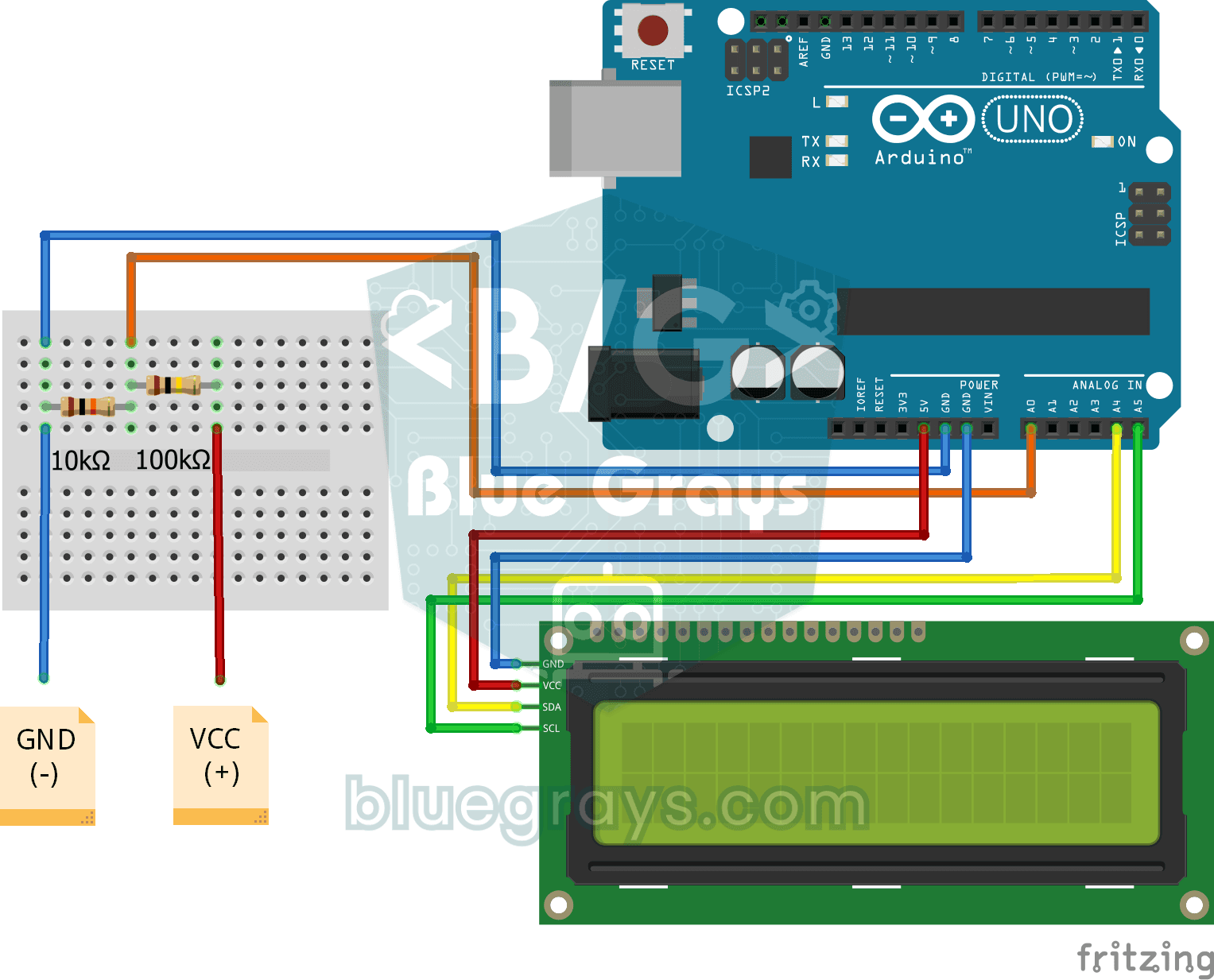
Digital Voltmeter with LCD Display
Find out how much voltage a battery or power adapter gives with a meter you built yourself. A divider made of two resistors brings high voltage down to a level the board can read, and the Arduino calc
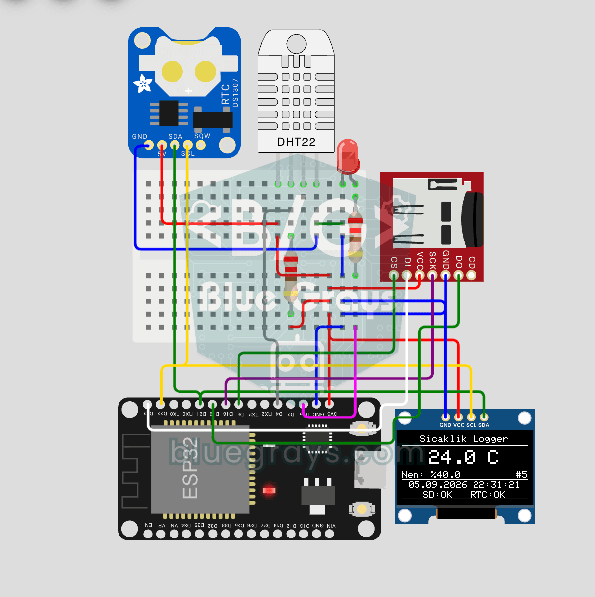
ESP32 Temperature Data Logger (DHT22 + DS1307 RTC + microSD + OLED)
Build a timestamped temperature logger with ESP32! Read DHT22 temperature/humidity every minute, get real-world time from DS1307 RTC, and log to microSD card as CSV. The OLED displays live temperature (large font), humidity percentage, timestamp, and log counter. The /temp_log.csv file on the SD card opens in Excel, Google Sheets, or Python pandas for analysis — perfect for greenhouse monitoring, home/room temperature tracking, laboratory data collection, food storage conditions, or beehiv

ESP32 HTTPClient + Weather API (with SSD1306 OLED Display)
In this project, we use the ESP32 to make a REST API call to a weather API (wttr.in) over the internet using HTTPClient.h. Unlike the previous I2C LCD version, we’re using an SSD1306 OLED (128×64) display here—which allows for large fonts, vector icons, and rich visual presentation on a single screen. Seven different vector icons for weather conditions (sunny, partly cloudy, cloudy, rainy, snowy, stormy, foggy) are drawn at runtime (no bitmap files required). The temperature is displayed in th
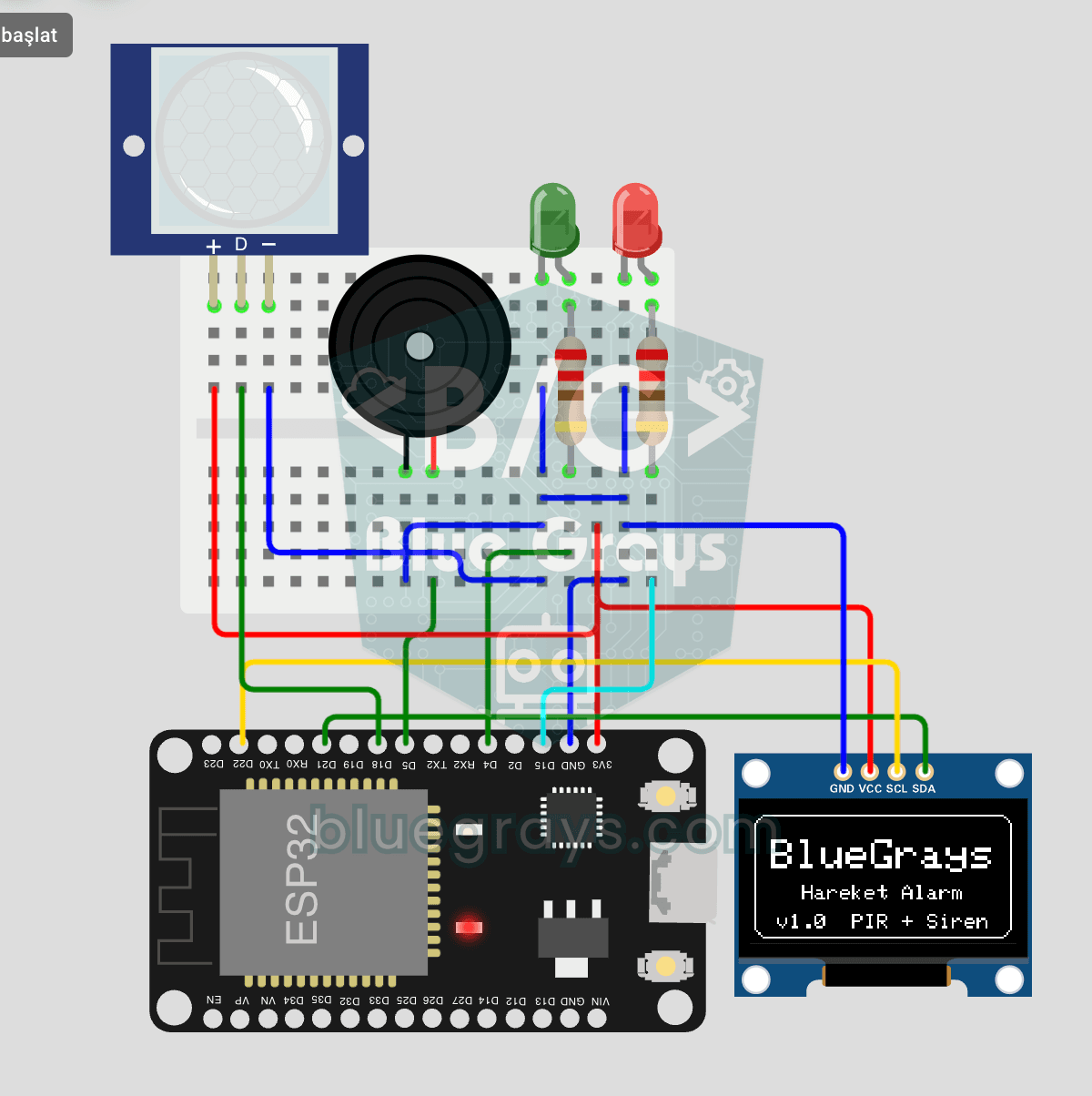
ESP32 Motion Alarm System (PIR + Buzzer + LED + Telegram)
A smart security alarm system that activates the buzzer and LED when the PIR sensor detects motion, while simultaneously sending an instant notification to the owner via Telegram. It includes a 30-second cooldown to limit the frequency of repeated alarms; this mechanism does not validate PIR detections or eliminate false triggers. Suitable for home security, garage monitoring, warehouses, or workrooms. With ESP32-CAM, photo notifications can be added; with the classic ESP32 DevKit V1, text notif

Bluetooth Controlled Car with L298N
Turn your phone into a remote and drive your own robot car. The Arduino receives commands from a remote-control app on your phone through a Bluetooth module and spins the wheels with a motor driver; t