
Arduino Projects Step by Step: How to Follow a Project Page
Arduino projects step by step: read the parts list, circuit diagram, code, Understand the code and test in the right order. Free LDR night light example.
When you follow Arduino projects step by step, the order is always the same: first read the parts list and the circuit diagram and build the circuit, then upload the code to the board, and finally understand what the code does and test the circuit. Breaking this order, copying the code first and looking at the circuit later, is where beginners lose the most time: the code uploads fine, the LED stays dark and nobody knows whether the problem is in the wiring or in the code. Every section of the project page serves one of these four jobs. Once you know which one to open when, you can usually finish a beginner project in a single session.
This post is the project page part of our series that walks through the BlueGrays app section by section. To keep it concrete, we use one real project from start to finish: project no. 12, Night Light with Ldr. It's free, rated Beginner, has a block view and is built from a seven-line parts list: when the room gets dark the LED turns on by itself, and when it gets bright again the LED turns off. First you'll see the sections of the page in a table, then we'll read each section with this project, and at the end we'll talk about choosing your next project, difficulty levels and moving up a level. You can copy the checklist at the end and use it for every project.
Which sections does the project page have?
When you tap a project, the project photo opens at the top with the difficulty level, the platform, a Free label if it's free and the project number (#12 for the night light). Below it you'll find the project name, the star rating and how many people rated it, the … people finished line and a short description. Then come three tiles (I made it, Rate, Favorite) and the main button of the page, Build it step by step. Under the Resources heading there are three collapsible sections: Project Video, Circuit Diagram and Source Code. At the very bottom sit Required Components and Troubleshooting. The thing to notice: the order on the screen is not the order you work in. The parts list is at the bottom of the page, but it's the first place you should look.
| Section | What it shows | When to open it | In a free project |
|---|---|---|---|
| Required Components | Parts, their quantities (×1, ×5) and special names (330R, 10k) | First, before you open the box or go shopping | Open |
| Circuit Diagram | Every connection between the board and the breadboard; zoomable, saved to your phone with Save to Gallery | When your parts are complete, while you build | Open |
| Project Video | What the project looks like when it works (in most projects) | Once before building, again while testing | Open |
| Source Code | The code to upload; Copy and Copy Link buttons | After the circuit is built | Open |
| Show as blocks | The same program as blocks (in projects with blocks) | If the code is hard to read | Open |
| Understand the code | Summary, step-by-step explanation, If you get stuck and Try it yourself | After uploading, before you change anything | Open |
| Troubleshooting | A list of checks (10 steps for the night light) | If the circuit doesn't behave as expected | Unlocked with Premium |
| Let's build it together | Guided mode with Parts, Circuit, Code and Test steps | If you want to do the project in one flow | Open |
The recommended order: following a project in 7 steps
- Read the description, watch the video: Don't start building without knowing what the result should be. For the night light the goal is one sentence: "The LED turns on in the dark and off in the light."
- Required Components: Put every line on the table with its quantity and special name, and note what's missing.
- Circuit Diagram: With the USB cable unplugged, place the wires in the order shown and check each wire at both ends.
- Source Code: Get the code onto your computer, select the board and port in the Arduino IDE and upload.
- Match the code to the diagram: Confirm that every pin number in the code has a wire in the diagram.
- Test: Try the expected behaviour one item at a time; if it doesn't work, check If you get stuck inside Understand the code, then Troubleshooting.
- Understand and change: Read Understand the code, change one value, predict the result, upload again, then mark the project with I made it.
Required Components: reading quantities and special names
Each line of the parts list has a photo, the part name, a small special name underneath if needed, and the quantity on the right. The special name tells you which value a part of that type must have. The Night Light with Ldr list has seven lines and two of them are Resistor: one is 330R, the other 10k. These two resistors can't be swapped. The 330R limits the current through the LED; the 10k forms a voltage divider with the LDR and decides the number the code reads. Numbers like ×5 on the right matter too: the jumper wire count matches the number of wires in the diagram exactly. If you count 5 wires on the table, you should see 5 wires in the diagram; if there's one more or one less, either you're misreading the diagram or a connection has been skipped.
| Line | Qty | Special name | Job in the project |
|---|---|---|---|
| Arduino Uno | ×1 | – | Runs the code; D13 output, A0 analog input |
| Breadboard | ×1 | – | Solderless connection board |
| LED | ×1 | – | The lamp that lights up in the dark |
| Resistor | ×1 | 330R | Limits the LED current (orange-orange-brown) |
| Resistor | ×1 | 10k | Voltage divider with the LDR (brown-black-orange) |
| Jumper wire | ×5 | – | D13, GND, A0, 5V and one bridge on the breadboard |
| LDR | ×1 | – | Light sensor; its resistance rises as light falls |
If a part is missing, first think about what could replace it. Any resistor between 220 Ω and 1 kΩ will light the LED instead of the 330R; the higher the value, the dimmer the LED. Don't replace the 10k, though: the threshold in the code was chosen for this resistor, and a different one shifts the darkness level at which the LED turns on. If you're not sure what a part is, tap its line; the component page opens with a description and the Used in Projects list (some component pages are Premium). If you save the parts you own under Parts in the Workshop tab, the app lists the projects you have every part for under Projects You Can Build and the ones missing a part or two under Projects with Missing Components. Parts is a Premium feature; we'll cover it in a later part of the series.
How to read the Circuit Diagram
When you open the Circuit Diagram section you see a small version of the diagram; tap it to open it full screen and zoom with your fingers. The Save to Gallery button below saves it to your phone's gallery, so you can look at it from the gallery while you build or open it large on a computer screen. BlueGrays diagrams are a top view of the board and the breadboard, so you don't need to decode symbols, but you do need to know how the breadboard is connected inside. On a breadboard, the five holes in each numbered column (A–E or F–J) are connected to each other, and the gap in the middle separates the two halves. So plugging two legs into the same number on the same half connects them. While reading the diagram, ask this for every leg: "Which number is this leg in, and what else is in the same number?" For a closer look at how a breadboard works, see what is a breadboard.
In the Night Light with Ldr diagram, the LED's two legs sit in holes H7 and H8; the bent, longer leg (anode, plus) is in column 7. The 330 Ω resistor runs from I3 to I7, and a red wire goes from J3 to pin 13 on the board. So current flows from D13 into the resistor and from there into the LED's long leg. From column 8, where the LED's short leg is, a blue wire goes down to the board's GND pin, and a short blue bridge runs from I8 to I12. The 10 kΩ resistor sits between F12 and F16, the LDR between H16 and H19. The yellow wire goes from J16 to A0, the red wire from J19 to 5V. In short, there are two paths: 5V, LDR, junction (A0), 10 kΩ and GND form a voltage divider, and D13, 330 Ω, LED and GND form the LED path.
Four rules come out of this diagram, and you'll use them in every project. First, wire colours: here red carries 5V and the D13 signal, yellow carries A0 and blue carries GND. The colour doesn't change the electricity, but if you use the same scheme, checking becomes easier. Second, a shared GND: the LED and the 10 kΩ resistor don't each run to a GND pin; thanks to the I8–I12 bridge they share a single GND wire. Every GND point in the circuit must meet at the board's GND. Third, LED direction: the long leg faces the plus side, the signal coming from the resistor; the short leg and the flat edge on the LED body face GND. An LED placed backwards won't light, but it usually isn't damaged. Fourth, the resistor value: with 330 Ω, about (5 − 2) / 330 ≈ 9 mA flows through a red LED, which is safe and bright enough. You can do the maths for your own LED with the LED resistor tool and check a resistor's value with the colour code tool.
| Diagram reading mistake | Symptom | How to spot it |
|---|---|---|
| Two legs on different sides of the gap | The LED or LDR acts as if it isn't connected at all | Look at the letters: if one is in row E and the other in F, they're on opposite sides |
| Off by one hole | The LED stays dark or A0 reads random values | Compare the number in the diagram with the number on your breadboard |
| LED backwards | The L light on the board turns on, but the external LED doesn't | Is the long leg in the same column as the 330 Ω? |
| 330R and 10k swapped | The LED is very dim and the night light doesn't react at the expected darkness | Read the colour bands or measure with a multimeter |
| LDR and 10k swapped | The LED turns on in the light and off in the dark | Does the free end of the LDR go to 5V and the free end of the 10k to GND? |
| GND wire or bridge missing | Nothing works, or only one path works | Is the blue wire in the same column as the LED's short leg, and does the bridge reach 12? |
| Wire one pin off on the board (12 or A1) | The code uploads but the circuit doesn't react | Follow the pin label on the board down to the socket the wire is in |
Source Code: copy it, move it to your computer, upload it
The Source Code section has two buttons. Copy puts the code on your phone's clipboard, which is handy if you want to send it to yourself in a message. Copy Link creates a link for opening the code on a computer: send the link to yourself, open it in your computer's browser and copy the code from there. The link is valid for a short time (about an hour); if it expires, just create a new one in the app. In the Arduino IDE, open a new sketch, delete the empty setup and loop lines and paste the code. Then choose Arduino Uno under Tools > Board, the port your board is connected to under Tools > Port, and press Upload. If you're installing the IDE for the first time, see how to install the Arduino IDE; if the upload fails, Arduino code won't upload will help. The night light code is short; below is a version with comments in two languages, with the same pins and threshold as in the app.
1int value;   // Işık okuması (0-1023) / Light reading (0-1023)
2
3void setup() {
4  pinMode(13, OUTPUT);   // LED çıkışı / LED output
5}
6
7void loop() {
8  value = analogRead(A0);   // Işık seviyesini oku / Read the light level
9
10  // Eşik 50: altı karanlık sayılır / Threshold 50: anything below counts as dark
11  if (value < 50) {
12    digitalWrite(13, HIGH);   // Karanlık: LED yanar / Dark: LED on
13  } else {
14    digitalWrite(13, LOW);    // Aydınlık: LED söner / Bright: LED off
15  }
16}
17
How to match the code to the diagram
If the code uploads but the circuit doesn't work, most problems come from a pin in the code not matching a wire in the diagram. The systematic way to find this is simple: mark every pin number and pin name in the code, one by one, and find a wire in the diagram for each. A pin that appears in the code but has no wire in the diagram, or a signal wire in the diagram that never appears in the code, points to the mistake. The night light code uses only two pins: 13 and A0. 5V and GND don't appear in the code because they're supply lines, but they're always in the diagram. When you change the project yourself, for example by moving the LED from pin 13 to pin 8, filling in this table again catches the mistake before you even upload.
| Line in the code | In the diagram | Question to check |
|---|---|---|
| pinMode(13, OUTPUT); | Red wire: J3 → D13 | Is the wire really in 13 on the board, not 12? |
| digitalWrite(13, HIGH / LOW); | D13 → 330 Ω → LED long leg → short leg → GND | Are the LED direction and GND wire correct? |
| value = analogRead(A0); | Yellow wire: J16 → A0, the junction of the LDR and the 10k | Is the yellow wire in the same column (16) as the LDR and the 10k? |
| if (value < 50) | Voltage divider: 5V → LDR → A0 → 10 kΩ → GND | Is the LDR on the 5V side? If it's reversed, the logic is reversed too |
| (not in the code) 5V and GND | Red J19 → 5V, blue J8 → GND, blue bridge I8–I12 | Do all GND points meet at the same place? |
The threshold is linked to the diagram too. analogRead(A0) turns the 0–5 V on A0 into a number between 0 and 1023. Because the LDR is on the 5V side in this circuit, its resistance drops as the light increases and the reading goes up. For the reading to fall below 50, the LDR's resistance has to rise above roughly 195 kΩ, which only happens when it's quite dark. If the LED stays off even when you cover the LDR with your hand, the code isn't broken; the threshold is just too low for your room. To see your own room's values, upload the Measuring Light Intensity with an LDR project, which uses the same LDR and 10k wiring; the value is printed in the Serial Monitor every half second. Pick a number close to the middle of your bright and dark readings as the threshold. We cover the Serial Monitor in detail in this post; if you're curious about the LDR itself, read LDR light sensor.
Show as blocks and Understand the code
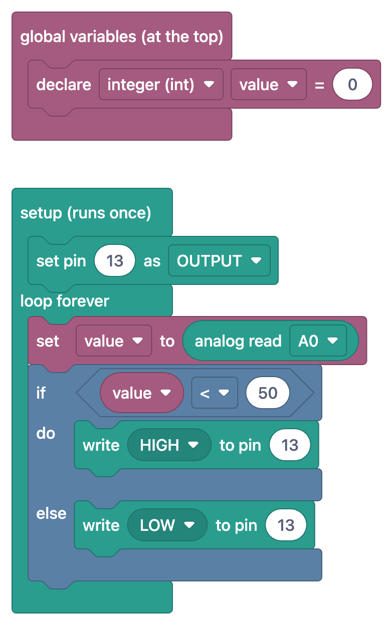
In projects with a block view, the Source Code section has a Show as blocks switch. Turn it on and the same program appears as blocks in the app's language; tap the image to open it full screen. In the night light the blocks match the code one to one: the value declaration inside the global variables block, the block that sets pin 13 as OUTPUT inside setup, and the analog read plus the if block with the value < 50 condition inside the repeat-forever loop. If a line of code confuses you, switching on the blocks and looking at the same spot is often enough. Set the right expectation, though: blocks are for reading and understanding. You can't edit blocks in the app and they aren't uploaded to the board; the board always gets the code from Source Code. For a closer look at the if block, we also covered this project in the block coding if block.
The Understand the code tab next to Source Code has four parts: the What does this code do? summary, the Step by step explanation (5 steps for the night light, each with the relevant code snippet and an explanation), If you get stuck with common symptoms and fixes, and finally the Try it yourself task. In this project the task is to raise the threshold from 50 to 300 and slowly cover the LDR with your hand to see when the LED comes on; if you get stuck, Hint and Show solution help. With Show as blocks on, the tab is called Understand the blocks. Understand the code is open in free projects. We'll cover this section in detail in the next post of the series; for now, remember the rule: read Understand the code after uploading and before you change anything.
Testing, Project Video, Troubleshooting and Let's build it together
Test against the expected behaviour, not at random. Three checks are enough for the night light: with the room bright the LED should be off; when you cover the LDR completely with your finger the LED should turn on; when you take your finger away it should turn off. If the LED never turns on, look at the L light on the board: on the Arduino Uno it's connected to pin 13. If L lights up but the external LED doesn't, the code is working and the problem is in the LED wiring. If L stays off too, either it isn't dark enough to go below the threshold or the problem is on the A0 side; set the threshold to 300 temporarily and try again. To compare the result, open the Project Video section and see how the project should look when it works. Watching the video once before you build also makes it clear from the start what you're going to test.
The Troubleshooting section is a checklist that starts with the sentence "If your project is not working, check the steps below." For the night light there are 10 steps: power, uploading the code, pin numbers, breadboard connections, jumper wires, GND, the LED not lighting, the resistor value, the LED's leg direction and whether the LED might be burnt out. This section is unlocked with Premium, even in free projects; on the free plan you can see how many steps the list has. In a free project, first aid comes from If you get stuck inside Understand the code; for the night light it lists five symptoms and their fixes, such as "the LED turns on in the light and off in the dark". A multimeter makes checking wires and resistors much easier; if you've never used one, start with how to use a multimeter.
If you'd rather move through it in one flow instead of switching between sections, tap the Build it step by step button at the top of the page. Guided mode splits the project into four steps: 1. Get the parts ready (you tick off the parts you have), 2. Build the circuit, 3. Upload the code and 4. Run and test. The screen stays on while the mode is open, and if you stop halfway the button shows where you left off, like "Continue · Step 2 / 4". The order in this post and the order of the guided mode are the same; the difference is that the guide keeps you focused on just the information for the current step. We'll cover this mode from start to finish in a separate post.
When you're done: I made it, Rate and your next project
If the project works, tap the I made it tile at the top of the page; the project is marked as completed, the tile changes to Made and the project is added to the Completed Projects list in your Workshop. If you use Premium and keep your parts in the Workshop, the app may first ask you to add the project's parts if they aren't in your Workshop. With Rate you give the project 1 to 5 stars; your rating feeds into the average on the page and the Highest Rated sort. Favorite adds the project to your favourites, where you can collect projects you want to build again or show someone. We also suggest taking a note right when you finish: which threshold worked in your room, which wire did you plug in wrong? Those notes stop you from making the same mistake in your next project.
To choose your next project, use the Filter and Sort buttons together in Discover › Projects. The filter offers Difficulty Level, Platform, Price, Components, Projects with blocks, IoT projects and, under Workshop Filter, Only Buildable. You can sort by Newest, Oldest, Name, Most Completed and Highest Rated. A useful combination for beginners: Platform Arduino, Price Free, Difficulty Level Beginner and sorting by Oldest. The first projects cover basics like LEDs, buttons, the LDR and the buzzer in order, so the list moves you forward step by step. If you want to keep going with the parts you have, pick LDR or LED in the Components filter and list the projects you can build with the same parts. The IoT projects filter shows the 8 free template projects made for BlueGrays IoT: you add an ESP32 or Raspberry Pi Pico W under Workshop › My devices › Add new device, Ohmi prepares the code with the device key, and you upload it once from the Arduino IDE with the BlueGraysIoT library; then switches, live values and charts appear on your phone (2.4 GHz Wi-Fi required). We cover every step in the guide to controlling an ESP32 from your phone.
What do the difficulty levels mean, and when should you move up?
Every project carries a Beginner, Intermediate or Advanced label. The label doesn't only describe the length of the code; it also reflects how many parts the circuit has, whether a library is needed and how hard it is to find the problem when something goes wrong. The table below brings together the typical features of each level, example projects from each and the sign that you're ready for the next level.
| Level | Typical circuit | Typical code | Example projects | Sign you're ready for the next level |
|---|---|---|---|---|
| Beginner | 1–3 main parts, no library | Up to 30 lines, a single condition or loop | Night Light with Ldr, Traffic Light (free) | You can build the circuit from the diagram without mistakes and predict what the code will do |
| Intermediate | One sensor or module and a few outputs, sometimes a library | 30–100 lines, arrays, several conditions | LED Chaser with Adjustable Speed, Temperature and Humidity with DHT11 (free) | When you change a value in the code, you can say the result in advance |
| Advanced | Several modules, a display, motors or a wireless link | Over 100 lines, state tracking, timing | Smart Irrigation Station, Obstacle Avoidance Robot (Premium) | You can find the problem in a circuit that doesn't work on your own |
A rule that works for moving up: finish three projects at one level, including their Try it yourself tasks, then move to the next level. After the night light, a natural route could be: first, with the same parts, see the sensor values as numbers in Measuring Light Intensity with an LDR. Then move to LED Chaser with Adjustable Speed, a circuit with 6 LEDs, 6 × 330R resistors, a potentiometer and 16 jumper wires; as the parts list grows, your diagram reading habit is really put to the test. Next, in Temperature and Humidity with DHT11 you work with a library and an I2C LCD display for the first time. Advanced projects are Premium; when you get there, the Troubleshooting lists and the Understand the code steps for longer code help even more. If you get stuck twice on a project, going back a level to do a similar project isn't a step backwards; it's often the fastest way forward.
A project checklist you can copy
- Read the description and watch the Project Video; write down in one sentence what should happen at the end.
- Put every line from Required Components on the table with its quantity and special name (for example: Resistor ×1 330R, Resistor ×1 10k).
- Note any missing parts; think about a substitute value or choose another project you can build with the same parts.
- Confirm the resistor values from the colour bands or with a multimeter.
- Save the Circuit Diagram to your phone with Save to Gallery and zoom in when needed.
- With the USB unplugged, place the wires in the order of the diagram; for every leg, check the number and which side of the gap it's on.
- Check that the LED's long leg faces the plus side, the short leg faces GND, and that all GND points are joined.
- Move the code to your computer with Copy or Copy Link, select the board and port in the Arduino IDE and upload.
- Find a wire in the diagram for every pin number in the code; fix anything that doesn't match.
- Test the expected behaviour step by step; if it doesn't work, check If you get stuck first, then Troubleshooting.
- Read Understand the code and do the Try it yourself task; change one value and predict the result first.
- Mark the project with I made it, rate it with Rate and choose your next project with the filters.
Once you've used this order on a few projects, you won't need the list any more: parts list, diagram, code, understanding and testing will fall into place on their own. The night light is a good place to build the habit, because one small circuit shows a voltage divider, a threshold, LED direction and a shared GND all together. If you'd like to try it, open Night Light with Ldr in the BlueGrays app and work through it in the order from this post; in all 60 free projects (20 per platform), the parts list, circuit diagram, code and Understand the code are open.
Frequently asked questions
How do you do an Arduino project step by step?
First read what the project should do and prepare the parts list, then build the circuit from the diagram with the USB cable unplugged. Next, paste the code into the Arduino IDE, select the board and port, and upload. Finally, test the expected behaviour and work through what the code does step by step.
How do you read an Arduino circuit diagram?
Check which numbered column of the breadboard each leg is plugged into; the five holes in the same number are connected and the gap in the middle separates the two halves. Then follow each wire from both ends to see which pin on the board it goes to. Matching the pin numbers in the code to the wires in the diagram is the fastest way to find mistakes.
How do you upload ready-made Arduino code?
Copy the code, paste it into a new sketch in the Arduino IDE, choose your board (for example Arduino Uno) and port in the Tools menu, then click Upload. In BlueGrays, the Copy Link button creates a short-lived link for opening the code in your computer's browser. If the upload fails, check the USB cable and the board and port selection first.
Why won't my LDR night light turn on?
There are two common reasons: the threshold is too low for your room, or the LDR and the 10 kΩ resistor have been swapped. In the Night Light with Ldr project the LED turns on when the reading drops below 50, which only happens when it's quite dark. Raise the threshold to 200–300 and try again; if the LED works the wrong way round, check that the LDR goes to 5V and the 10k to GND.
Which Arduino project should a beginner start with?
Projects that teach one new idea at a time, such as blinking an LED, a traffic light, an LED with a button and an LDR night light, are a good start. They use 1–3 main parts and short code, so mistakes are easy to find. In BlueGrays these projects are free and rated Beginner.
What is open in BlueGrays free projects?
In the 60 free projects (20 per platform), the parts list, circuit diagram, source code, Understand the code and, where available, the blocks are open. The Troubleshooting list and Workshop › Parts are unlocked with Premium. You can use the I made it, Rate and Favorite tiles in free projects too. In BlueGrays IoT your first device is free: the free plan gives you 1 device, chart history for 1 value and 24 hours of history; Premium unlocks 10 devices, chart history for 20 values and 30 days.
Projects to build after reading this
See all projects
Night Light with Ldr
A little night light that turns on by itself when it gets dark and goes off when morning comes. A light sensor measures how bright the room is, and the Arduino switches the LED on when it is dark enou

Measuring Light Intensity with an LDR
Want to see how bright your room is as a number? The LDR, a small part that reacts to light, measures the light around it, and the Arduino writes the value to your computer screen every half second. C

LED Blink
The very first hello of electronics: switching a single LED on and off. The Arduino turns the LED on and off at short intervals, so the light blinks quickly. You see in the simplest way how the board

Traffic Light
A tiny copy of the traffic light you see on the road every day. Red stays on for two seconds, yellow flashes for a moment, green stays on for two seconds, then it goes back to red through yellow again

LED Control with a Push Button (Push)
Just like a doorbell: the light stays on as long as you press, and goes off when you let go. The Arduino keeps listening to the button; while it's pressed the LED is on, and the moment you lift your f

Toggle an LED with a Button (On/Off)
Press the button once and the light comes on, press it again and it goes off, just like the light switch in your room. The Arduino notices every press and flips the LED to the opposite state, waiting

LED Chaser with Adjustable Speed
Six LEDs light up one after another, so the light seems to run from one end to the other. Turn the potentiometer knob and the speed of that run changes instantly: one way and the light races along, th
Temperature and Humidity with DHT11
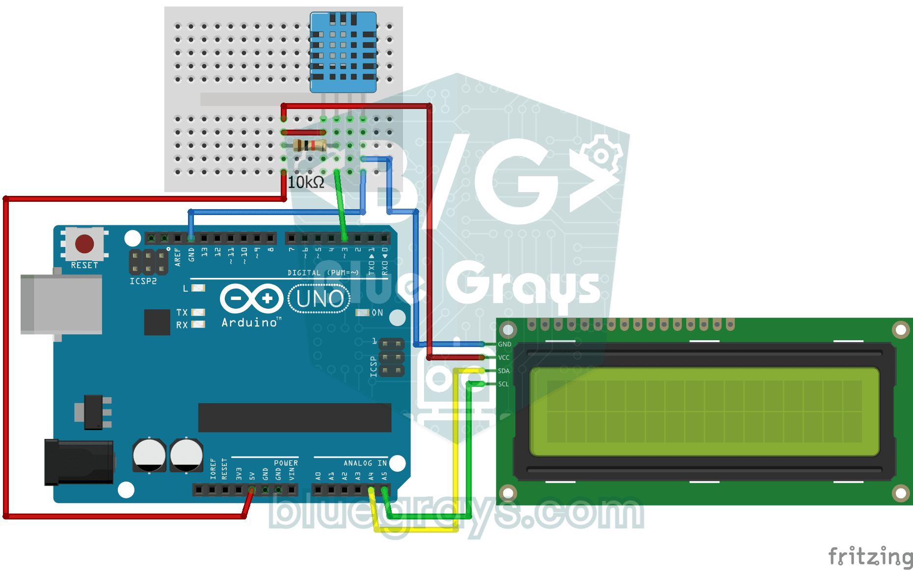
How warm is your room, and is the air humid or dry? The DHT11 sensor measures temperature and humidity, and the Arduino writes the values on a two-line LCD screen, refreshing every couple of seconds.