
ESP32 OTA Update: Upload Code Wirelessly with ArduinoOTA
ESP32 OTA lets you upload code over Wi-Fi with no USB cable: ArduinoOTA network port, ElegantOTA web page, password, partition scheme and dropped uploads.
ESP32 OTA (Over-The-Air update) means uploading new code to your board over Wi-Fi instead of plugging in a USB cable. Picture a sensor mounted on the ceiling, an irrigation controller in the garden or a relay board tucked inside an electrical cabinet: instead of grabbing a ladder, unmounting the board and connecting it to your computer for every small fix, you send the new version from the Arduino IDE or a browser in a few seconds. The board writes the new program into its memory in the background, verifies it and restarts itself.
In this guide you'll learn step by step how OTA works inside the ESP32, three different methods (ArduinoOTA for the Arduino IDE, ElegantOTA for the browser and HTTPUpdate for pulling from a server), how to pick the right partition scheme, how to protect uploads with a password, what happens if an upload is interrupted and how to avoid losing OTA in your next sketch. All the code has been compiled and tested with the ESP32 Arduino core.
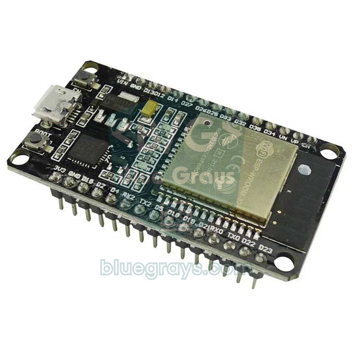
What is ESP32 OTA and how does it work?
The ESP32's flash memory isn't one single block; it is split into pieces by a map called the partition table. A partition table that supports OTA has two identical areas for the program: app0 (ota_0) and app1 (ota_1). While the board runs from one of them, the new program is written into the other. A small otadata partition stores which area will run at the next boot. This way the running program is never touched during the upload, and the board doesn't give up the old program until the new code has been completely written and verified.
- The new program (the compiled .bin file) arrives at the board over Wi-Fi, piece by piece.
- The ESP32 writes each piece to the program partition that is not in use right now; the running code keeps doing its job in the meantime.
- Once the whole file has arrived, the image header and checksum are checked; a corrupted or incomplete file is rejected.
- If verification succeeds, otadata is updated: the new partition will run at the next boot.
- The board restarts and comes up with the new program. The next update goes into the other partition; the two areas are used in turn.
| Method | Where do you send the code from? | Best suited for | Extra library |
|---|---|---|---|
| ArduinoOTA | From the network port in the Arduino IDE | Developing at your desk, on the same network | None (comes with the core) |
| ElegantOTA | By choosing a .bin on the /update page in the browser | Letting someone without the IDE update, uploading from a phone | ElegantOTA |
| HTTPUpdate | The board downloads a .bin file from a server by itself | Many devices, remote devices, automatic updates | None (comes with the core) |
Partition scheme and flash size
This is the most overlooked requirement of OTA: there must be a second free area to write the new program into. That's why the largest program you can upload over OTA is smaller than even half of the flash. You choose the partition table in the Arduino IDE under Tools > Partition Scheme. On the common ESP32 DevKit boards with 4 MB of flash (ESP32 Dev Module), the options are:
| Partition Scheme | Program area | OTA | File system (SPIFFS/LittleFS) |
|---|---|---|---|
| Default 4MB with spiffs | 2 × 1.25 MB (1,310,720 bytes) | Yes | 1.375 MB |
| Minimal SPIFFS (1.9MB APP with OTA) | 2 × 1.875 MB (1,966,080 bytes) | Yes | 128 KB |
| No OTA (2MB APP/2MB SPIFFS) | 1 × 2 MB | No | 1.875 MB |
| Huge APP (3MB No OTA/1MB SPIFFS) | 1 × 3 MB | No | 896 KB |
| Minimal (1.3MB APP/700KB SPIFFS) | 1 × 1.25 MB (for boards with 2 MB flash) | No | 640 KB |
You can see how much space your program takes in the compile output: our first example with Wi-Fi and ArduinoOTA prints "Sketch uses 758685 bytes (57%) ... Maximum is 1310720 bytes". The maximum here is the size of a single program area in the scheme you selected. If usage goes above 90%, expect to move to Minimal SPIFFS soon. One more important rule: the partition table can't be changed over OTA. If you changed the scheme, that upload must be done over USB; later OTA updates work with the new table. On boards with 8 MB or 16 MB of flash (such as many ESP32-S3 models), choosing the correct size in the Flash Size menu gives you much larger OTA areas.
If you want to see which partition your board is actually running from and how much room is left for OTA, upload the small sketch below. It needs no library and uses the ESP-IDF OTA functions directly:
1#include <esp_ota_ops.h>
2
3void setup() {
4  Serial.begin(115200);
5  delay(1000);
6  const esp_partition_t* running = esp_ota_get_running_partition();
7  const esp_partition_t* next = esp_ota_get_next_update_partition(NULL);
8
9  Serial.printf("Flash boyutu / Flash size: %u KB\n", ESP.getFlashChipSize() / 1024);
10  Serial.printf("Program boyutu / Sketch size: %u KB\n", ESP.getSketchSize() / 1024);
11  Serial.printf("OTA icin bos alan / Free space for OTA: %u KB\n", ESP.getFreeSketchSpace() / 1024);
12  Serial.printf("Calisan bolum / Running partition: %s (0x%06x)\n", running->label, running->address);
13  if (next != NULL) {
14    Serial.printf("Siradaki OTA bolumu / Next OTA partition: %s (0x%06x)\n", next->label, next->address);
15  } else {
16    Serial.println("OTA bolumu yok: bolum tablosunu degistir / No OTA partition: change the partition scheme");
17  }
18}
19
20void loop() {
21}
With the default scheme, after the first USB upload the output reads "Running partition: app0 (0x010000)" and "Next OTA partition: app1 (0x150000)". Run the code again after an OTA update and you'll see it now runs from app1. The value of ESP.getFreeSketchSpace() is the size of the largest program you can upload over OTA; if your new .bin file is larger, the update won't start.
Method 1: wireless upload from the Arduino IDE with ArduinoOTA
The ArduinoOTA library comes with the ESP32 core, so there's nothing to install. Once the board joins the network it announces itself via mDNS; the Arduino IDE sees this and adds a network port to the Port menu. When you press Upload, the IDE sends the program through this network port instead of USB. On the ESP32 the OTA service listens on port 3232 by default. The sketch below connects to Wi-Fi, starts OTA with a password and blinks the onboard LED as proof:
1#include <WiFi.h>
2#include <ArduinoOTA.h>
3
4const char* WIFI_SSID = "AgAdi";          // Wi-Fi adın / your Wi-Fi name
5const char* WIFI_PASS = "AgSifresi";      // Wi-Fi şifren / your Wi-Fi password
6const int LED_PIN = 2;                    // çoğu DevKit'te dahili LED / onboard LED on most DevKits
7
8unsigned long lastBlink = 0;
9
10void setup() {
11  Serial.begin(115200);
12  pinMode(LED_PIN, OUTPUT);
13
14  WiFi.mode(WIFI_STA);
15  WiFi.begin(WIFI_SSID, WIFI_PASS);
16  while (WiFi.status() != WL_CONNECTED) {   // bağlanana kadar bekle / wait until connected
17    delay(500);
18    Serial.print(".");
19  }
20  Serial.println();
21  Serial.print("IP: ");
22  Serial.println(WiFi.localIP());
23
24  ArduinoOTA.setHostname("bluegrays-esp32");  // IDE'de görünen ad / name shown in the IDE
25  ArduinoOTA.setPassword("ota1234");          // yükleme parolası / upload password
26
27  ArduinoOTA.onStart([]() {
28    // Güncelleme başlıyor: motorları, röleleri güvenli konuma al / update starting: put motors and relays in a safe state
29    String type = (ArduinoOTA.getCommand() == U_FLASH) ? "program" : "dosya sistemi / filesystem";
30    Serial.println("OTA basladi / started: " + type);
31  });
32  ArduinoOTA.onEnd([]() {
33    Serial.println("\nOTA bitti, yeniden baslatiliyor / done, rebooting");
34  });
35  ArduinoOTA.onProgress([](unsigned int progress, unsigned int total) {
36    Serial.printf("Ilerleme / Progress: %u%%\r", progress * 100 / total);
37  });
38  ArduinoOTA.onError([](ota_error_t error) {
39    Serial.printf("Hata / Error[%u]: ", error);
40    if (error == OTA_AUTH_ERROR) Serial.println("parola / auth failed");
41    else if (error == OTA_BEGIN_ERROR) Serial.println("baslatilamadi, yer yok / begin failed, no space");
42    else if (error == OTA_CONNECT_ERROR) Serial.println("baglanti / connect failed");
43    else if (error == OTA_RECEIVE_ERROR) Serial.println("veri alinamadi / receive failed");
44    else if (error == OTA_END_ERROR) Serial.println("bitirilemedi / end failed");
45  });
46
47  ArduinoOTA.begin();                         // OTA hizmetini başlat / start the OTA service
48}
49
50void loop() {
51  ArduinoOTA.handle();                        // her turda çağır, unutma / call on every pass, never forget
52
53  // delay() yerine millis(): OTA isteklerini kaçırmamak için / millis() instead of delay() so OTA requests aren't missed
54  if (millis() - lastBlink >= 500) {
55    lastBlink = millis();
56    digitalWrite(LED_PIN, !digitalRead(LED_PIN));
57  }
58}| Line | What does it do? |
|---|---|
| ArduinoOTA.setHostname("bluegrays-esp32") | The name shown in the IDE's Port list and on the network. If you have several boards, give each one a different name. |
| ArduinoOTA.setPassword("ota1234") | Without a password, anyone on your network can upload code to your board. The IDE asks for this password before uploading. |
| onStart / onEnd | Run when the update starts and ends. The ideal place to stop motors, switch relays off or show "Updating" on a display. |
| onProgress | Gives you the percentage; you can draw a progress bar on an LCD or OLED. |
| onError | Tells you the type of error: password, no space, connection, receive or end error. |
| ArduinoOTA.handle() | Checks for incoming OTA requests. If it isn't called often inside loop(), the board can't answer the IDE. |
Step by step: your first OTA upload
- Edit the WIFI_SSID and WIFI_PASS values in the code for your network. The ESP32 only connects to 2.4 GHz networks.
- In the Tools menu, select your board (e.g. ESP32 Dev Module) and a Partition Scheme that includes OTA (Default or Minimal SPIFFS).
- Do the first upload with a USB cable. This step is required because the board doesn't have OTA code yet.
- Open the Serial Monitor at 115200 baud and write down the IP address the board prints.
- Unplug the USB cable and, if you like, power the board from another supply. Within 10–20 seconds a line like "bluegrays-esp32 at 192.168.1.x" appears under network ports in Tools > Port; select it.
- Change the LED delay in the code from 500 to 100 and press Upload. When the IDE asks for the password, type "ota1234".
- In the output window you'll see the progress percentage and finally a line such as "Done" or "Result: OK". The board restarts and the LED now blinks fast.
There's one limitation you should know: the network port is for uploading only, and the Serial Monitor doesn't work wirelessly. To see the board's messages, either plug USB back in or show the status on a web page, a display or via MQTT messages. While developing at your desk you can also leave the board on USB and still upload over the network; that way you get fast uploads and the Serial Monitor at the same time.
Password protection and security
A board with the OTA service open is a door through which anyone on your network can upload code. In ArduinoOTA, setPassword() keeps the password as plain text inside the code; if you're going to share the code, you can pass the MD5 hash of the password with setPasswordHash() so the password itself doesn't appear in the source. ElegantOTA protects the /update page with a username and password (HTTP Basic Auth).
- Give each device a different, hard-to-guess password: values like "1234" or "admin" are the first ones anyone tries.
- Don't expose the board to the internet: opening OTA or the /update page to the outside with port forwarding on your router is a serious risk; these methods run over unencrypted HTTP.
- Use HTTPUpdate for remote devices: since the board requests the update itself, an outgoing connection is enough; if you fetch over the internet, prefer HTTPS with WiFiClientSecure.
- Go to a safe state during the update: stop motors and switch off heater and pump relays inside onStart. The restart takes a few seconds and the pins may be undefined during that time.
Method 2: upload a .bin from the browser with ElegantOTA
ElegantOTA adds a neat /update page to the web server running on the ESP32. You open this page from your phone or from any computer without the Arduino IDE, select the compiled .bin file and upload it; the progress bar appears in the browser. It's the most practical method when you hand the device over to someone else or update it in the field.
- In the Arduino IDE open the Library Manager, search for ElegantOTA (Ayush Sharma) and install it.
- Edit the code below and upload it over USB the first time.
- Open the address printed in the Serial Monitor (e.g. http://192.168.1.42/update) in your browser and log in with the username "admin" and the password "ota1234".
- Keep Firmware selected as the mode and drag and drop the .bin file; when the upload finishes the board restarts by itself.
1#include <WiFi.h>
2#include <WebServer.h>
3#include <ElegantOTA.h>
4
5const char* WIFI_SSID = "AgAdi";          // Wi-Fi adın / your Wi-Fi name
6const char* WIFI_PASS = "AgSifresi";      // Wi-Fi şifren / your Wi-Fi password
7
8WebServer server(80);
9unsigned long otaProgressMillis = 0;
10
11void onOTAStart() {
12  Serial.println("OTA basladi / OTA started");     // röleleri kapat / switch relays off
13}
14
15void onOTAProgress(size_t current, size_t final) {
16  if (millis() - otaProgressMillis > 1000) {        // saniyede bir yaz / print once per second
17    otaProgressMillis = millis();
18    Serial.printf("%u / %u bayt / bytes\n", current, final);
19  }
20}
21
22void onOTAEnd(bool success) {
23  Serial.println(success ? "OTA basarili / OTA successful" : "OTA hatasi / OTA failed");
24}
25
26void setup() {
27  Serial.begin(115200);
28  WiFi.mode(WIFI_STA);
29  WiFi.begin(WIFI_SSID, WIFI_PASS);
30  while (WiFi.status() != WL_CONNECTED) {
31    delay(500);
32    Serial.print(".");
33  }
34  Serial.println();
35  Serial.print("Adres / Address: http://");
36  Serial.print(WiFi.localIP());
37  Serial.println("/update");
38
39  server.on("/", []() {
40    server.send(200, "text/plain", "BlueGrays ESP32 - surum / version 1.0");
41  });
42
43  ElegantOTA.begin(&server, "admin", "ota1234");   // /update sayfası + kullanıcı/parola / /update page + user/password
44  ElegantOTA.onStart(onOTAStart);
45  ElegantOTA.onProgress(onOTAProgress);
46  ElegantOTA.onEnd(onOTAEnd);
47
48  server.begin();
49}
50
51void loop() {
52  server.handleClient();     // web isteklerini işle / handle web requests
53  ElegantOTA.loop();         // başarılı yüklemeden sonra yeniden başlatır / reboots after a successful upload
54}
By default ElegantOTA works with the synchronous WebServer class that comes with the core, so the server.handleClient() and ElegantOTA.loop() calls in loop() are required. If your project already uses ESPAsyncWebServer, you can set the library's ELEGANTOTA_USE_ASYNC_WEBSERVER option to 1 and use it with the async server; we covered setting up the async server in the ESP32 Async Web Server and WebSocket post. The Filesystem mode on the page updates the LittleFS or SPIFFS image (web page files, settings files) instead of the program.
Getting the .bin file: exporting the compiled binary
For ElegantOTA and HTTPUpdate you need the compiled program file. In the Arduino IDE run Sketch > Export Compiled Binary. The IDE compiles the program and leaves several files in a build folder inside your sketch folder. Only one of them is suitable for OTA:
| File | Contents | Used for OTA? |
|---|---|---|
| myproject.ino.bin | The application only (your program) | Yes, this is the file to upload |
| myproject.ino.bootloader.bin | Bootloader | No |
| myproject.ino.partitions.bin | Partition table | No |
| myproject.ino.merged.bin (core 3.x) | Bootloader, table and program combined | No, it's only written over USB at address 0x0 |
Method 3: automatic updates from a server with HTTPUpdate
Imagine you have five sensor boards around the house. Instead of uploading to each one from the IDE, you put the new .bin file on a server and the boards download it themselves. The HTTPUpdate library that comes with the ESP32 core does this in a single line. In the example below the update starts when you press the BOOT button (GPIO 0) on the board:
1#include <WiFi.h>
2#include <HTTPUpdate.h>
3
4const char* WIFI_SSID = "AgAdi";
5const char* WIFI_PASS = "AgSifresi";
6// Bilgisayarındaki ya da sunucundaki .bin dosyası / the .bin file on your computer or server
7const char* FIRMWARE_URL = "http://192.168.1.50:8000/firmware.bin";
8const int BUTTON_PIN = 0;               // karttaki BOOT butonu / the BOOT button on the board
9
10void setup() {
11  Serial.begin(115200);
12  pinMode(BUTTON_PIN, INPUT_PULLUP);
13  WiFi.begin(WIFI_SSID, WIFI_PASS);
14  while (WiFi.status() != WL_CONNECTED) delay(500);
15  Serial.println("Hazir: guncellemek icin BOOT'a bas / Ready: press BOOT to update");
16}
17
18void loop() {
19  if (digitalRead(BUTTON_PIN) == LOW) {      // butona basıldı / button pressed
20    WiFiClient client;
21    httpUpdate.rebootOnUpdate(true);          // başarılıysa yeniden başlat / reboot on success
22    t_httpUpdate_return ret = httpUpdate.update(client, FIRMWARE_URL);
23
24    switch (ret) {
25      case HTTP_UPDATE_FAILED:
26        Serial.printf("Hata / Error (%d): %s\n", httpUpdate.getLastError(),
27                      httpUpdate.getLastErrorString().c_str());
28        break;
29      case HTTP_UPDATE_NO_UPDATES:
30        Serial.println("Guncelleme yok / No update");
31        break;
32      case HTTP_UPDATE_OK:
33        Serial.println("Tamam / OK");        // buraya genelde gelinmez, kart yeniden başlar / usually not reached, the board reboots
34        break;
35    }
36    delay(1000);
37  }
38}
To try it, put the .bin file in a folder on your computer as firmware.bin and run python3 -m http.server 8000 in that folder; replace the IP address in the code with your computer's local IP. In real use you replace the button with a timer: for example, once an hour the board reads a small "version.txt" file, and if the version number on the server is higher than its own, it starts the update. That way it also never gets stuck downloading the same file and restarting over and over.
What happens if the connection drops during OTA?
Short answer: your board won't be bricked. Because the new program is written to the unused partition and the boot partition is only switched after the whole file has been verified, an interrupted upload leaves the board running its old program. You'll see "Error Uploading" in the IDE, OTA_RECEIVE_ERROR in ArduinoOTA or a failed result in ElegantOTA; fix the problem and repeat the upload. If the power goes out mid-upload it's the same story: the board boots the old program. The only real risk is the new program itself being faulty: if you upload a program that doesn't connect to Wi-Fi or doesn't contain the OTA code, you'll need the cable again for the next update.
- Weak Wi-Fi signal: if the upload hangs around 30–60%, move the board closer to the router or use a module with an external antenna. If WiFi.RSSI() in the Serial Monitor is worse than -75 dBm, expect dropouts; see ESP32 won't connect to Wi-Fi for details.
- Not enough power: writing to flash and transmitting over Wi-Fi draw current at the same time. A weak USB port or a thin cable can reset the board during the upload; this shows up as a brownout error. Use a solid 5 V supply that can deliver at least 500 mA.
- Long waits inside loop(): waits like delay(5000) delay the handle() call and the IDE reports "No response from the ESP". Do your timing with millis().
- Firewall: with ArduinoOTA, when the upload starts the ESP32 connects back to your computer. If Windows Firewall or an antivirus blocks this incoming connection, the upload fails right away; allow private networks in the permission window that appears on the first attempt.
Keeping OTA in every new sketch
The most common OTA disappointment goes like this: you upload a completely different project over OTA, that project has no ArduinoOTA code, and the board no longer appears as a network port. The newly uploaded program replaces the old one completely; OTA isn't something that "stays on the board", every program has to carry it itself. To avoid climbing the ladder to the ceiling device again, make these rules a habit:
- Use a template: put the Wi-Fi connection and the ArduinoOTA settings in a separate function (e.g. setupOTA()) and start every new project from that file.
- Put the handle() call at the very top of loop() and never leave a loop that blocks for a long time inside loop().
- Reconnect if Wi-Fi drops: use WiFi.setAutoReconnect(true) or check the connection regularly; a board without a connection can't receive updates.
- Add a maintenance window to deep sleep projects: a sleeping board doesn't hear the OTA request. Write a mode that waits 60 seconds for OTA before sleeping if a button is held at boot or an MQTT flag has arrived. For sleep modes see the ESP32 Deep Sleep post.
- Test on a second board at your desk first: before sending to the device in the field, run the same code on a board next to you; if it connects to Wi-Fi and shows up as a network port, it's safe to send.
- Print a version number: keep an FW_VERSION constant at the top of the code and show it on the web page or display; you'll always know which version is running on which board.
OTA on the ESP8266 and Raspberry Pi Pico W
The ArduinoOTA and ElegantOTA code in this guide also runs on ESP8266 (NodeMCU, Wemos D1 Mini) boards with small changes: ESP8266WiFi.h is used instead of WiFi.h, ESP8266WebServer instead of WebServer, and the OTA port is 8266. On ESP8266 boards with 4 MB of flash, choose a Flash Size option that leaves enough program space for OTA. On the Raspberry Pi Pico W, the arduino-pico core offers ArduinoOTA support; here the new program is first downloaded into the LittleFS file system and copied into place at boot. That's why on the Pico W you have to reserve a file system area larger than your program in the Flash Size menu. MicroPython has no ready-made OTA tool; you can write small scripts that download and replace .py files over the network, but that isn't a verified two-partition update like on the ESP32.
OTA project ideas
- Ceiling or wall sensor: change the thresholds of a board measuring temperature, humidity and motion without touching a cable.
- Smart home relay: update the timing rules of the relay board in the electrical box over OTA; put the relays in a safe state inside onStart.
- Home Assistant devices: add new features over the network to sensors connected to Home Assistant via MQTT.
- Garden irrigation controller: change watering times and the soil moisture threshold without opening the waterproof box.
- Progress bar on an LCD: show the onProgress value as a percentage and a bar on a 16x2 LCD; the ESP32 OTA project in BlueGrays does exactly that.
- Fleet update: have several boards check the same server for a new version every night with HTTPUpdate.
Common mistakes and how to fix them
| Symptom | Likely cause | Fix |
|---|---|---|
| No network port in the Port menu | Board on a different network, mDNS blocked, the code doesn't call ArduinoOTA.begin() | Use the same 2.4 GHz network, restart the IDE, check that the IP is printed in the Serial Monitor |
| "No response from the ESP" | Long delay() in loop(), board busy or firewall | Use millis() instead of delay(), allow the IDE in the firewall |
| "Authentication Failed" | Wrong OTA password | Enter the setPassword value from the code; if you forgot it, upload once over USB |
| "Not Enough Space" / Begin Failed | Huge APP or No OTA scheme, program doesn't fit in the second area | Choose Minimal SPIFFS and upload once over USB; shrink the program |
| Upload stops halfway | Weak signal, power dip, dropped connection | Move the board closer to the router, use a solid 5 V supply, try again; the old program keeps running |
| Board doesn't join the network after the upload | New code has no Wi-Fi or OTA, wrong SSID | Fix it over USB; from now on start every project from the OTA template |
| "Wrong Magic Byte" or activation error in ElegantOTA | merged.bin, bootloader.bin or a file compiled for another chip was selected | Upload only the myproject.ino.bin file |
OTA is the key to taking ESP32 projects off your desk and mounting them somewhere real: once it's set up properly, fixes, new features and threshold changes arrive wirelessly in seconds. In the BlueGrays app you'll find the ESP32 OTA Update project (with IP and progress shown on an LCD) together with the Wi-Fi connection, Async Web Server, mDNS and NTP projects, each with a circuit diagram and code, step by step.
Frequently asked questions
What is ESP32 OTA?
OTA (Over-The-Air) means uploading a new program to the ESP32 over Wi-Fi instead of a USB cable. The board writes the new code to an unused program partition, verifies it and restarts with the new version. You need to upload the first OTA-enabled sketch once over USB.
Why doesn't the ESP32 network port show up in the Arduino IDE?
The most common reasons are the computer and the board being on different networks, a guest network isolating devices, and the ArduinoOTA.begin() call in the code never running. Check in the Serial Monitor that the board got an IP, restart the IDE and wait a few seconds.
Which partition scheme should I choose for ESP32 OTA?
On boards with 4 MB of flash choose Default (2 × 1.25 MB program area) or, if your program is large, Minimal SPIFFS (2 × 1.875 MB). Huge APP and No OTA have no second program area, so OTA doesn't work with them. The first upload after changing the scheme must be done over USB.
Can an interrupted OTA upload brick the ESP32?
No. The new program is written to an empty partition and the boot partition is switched only after the whole file has been verified. If the connection or the power is lost, the board boots the old program and you can simply try the upload again.
Can I use the Serial Monitor when uploading over OTA?
The network port is only for uploading code; the Serial Monitor doesn't work wirelessly. To see messages you can leave the board connected to USB or show the information on a web page, a display or via MQTT.
How do I set an ESP32 OTA password?
In ArduinoOTA you call ArduinoOTA.setPassword("password") before begin(); the IDE asks for this password before uploading. If you don't want the password visible in the code, pass its MD5 hash with setPasswordHash(). In ElegantOTA you protect the page with begin(&server, "user", "password").
Projects to build after reading this
See all projects
ESP32 OTA Update — Wireless Firmware Installation (With LCD Screen)
In this project, you’ll learn how to upload new firmware to the ESP32 over Wi-Fi without a USB cable. Using the ArduinoOTA library, the ESP32 becomes visible on the network and is automatically listed as bluegrays-ota in the "Network port" tab of the Arduino IDE. The initial upload is done via USB, and all subsequent updates are wireless—a critical feature for field devices. The I2C LCD screen displays the Wi-Fi status, IP address, hostname, OTA upload percentage, and error messages in both

ESP32 Wi-Fi STA Connection (with LCD Screen)
In this project, we connect the ESP32 to the home Wi-Fi network in Station (STA) mode in a secure, fault-tolerant manner. We store the SSID and password in a separate secrets.h file to prevent leaking to Git, set up an auto-reconnect mechanism, and display the RSSI signal level and IP address on an I2C LCD screen. The internal LED works as a status indicator. It is a production-grade connection manager.

ESP32 Asynchronous Web Server (with IP Display on LCD)
In this project, we’re turning the ESP32 into an asynchronous web server that you can control from your phone or computer on the same Wi-Fi network. Thanks to the ESPAsyncWebServer library, the server can process multiple requests simultaneously (unlike the classic WebServer.h, which blocks on a single request). You’ll be able to open the ESP32’s IP address in a browser and click the ON/OFF buttons (the /on and /off routes) to turn the LED connected to GPIO 5 on and off.

ESP32 mDNS: Accessing the Device via bluegrays-esp.local (with LCD Screen)
In this project, we add an mDNS (Multicast DNS) service to the ESP32, allowing us to access the device using a human-readable hostname like bluegrays-esp.local instead of an IP address. Even if the IP address assigned by DHCP changes, you can always reach the device using the same name. We also run a small web server on the device to send LED control commands via a browser using the address http://bluegrays-esp.local/. The I2C LCD screen displays the hostname, IP address, and LED status in b

ESP32 WebSocket Counter (2 Buttons + LCD + Real-Time Web)
In this project, two buttons wired to the ESP32 (GPIO 5 counts up, GPIO 4 counts down) change a counter. The value updates instantly both on a 16x2 I2C LCD and, through the WebSocket support of ESPAsyncWebServer, in every connected browser without reloading the page. Instead of HTTP polling a single persistent connection is used, and the ESP32 sends the new value to everyone with ws.textAll().

Real-Time Clock from the Internet via ESP32 NTP
The ESP32 connects to Wi-Fi and retrieves real time with millisecond precision from NTP (Network Time Protocol) servers. Thanks to the configTzTime() function, the Turkey time zone (TRT, UTC+3) is automatically applied, and DST transitions in countries that observe daylight saving time are automatically managed using a POSIX TZ string. The time is displayed both on the Serial Monitor and on an optional I2C LCD. configTzTime() starts the SNTP service; periodic resynchronization takes place wh

ESP32 HTTPClient + Weather API (with LCD Screen)
In this project, we use the ESP32 to make a REST API call to a weather API (wttr.in) over the internet using HTTPClient.h. We parse the returned JSON response using ArduinoJson v7 and display the city, temperature, humidity, weather, and wind information on an I2C LCD screen in both Turkish and English. wttr.in is free and does not require an API key—you can simply enter any city name to retrieve that city’s current weather conditions. It automatically updates every 30 minutes, provides differ

ESP32 Deep Sleep — Battery Saving (OLED + RTC RAM Counter)
The ESP32's Deep Sleep mode reduces current consumption to ~10 µA by shutting down the CPU and most peripherals, making it critical for battery-powered IoT devices. In this project, we use three different wake-up sources: a timer (15 seconds), an external pin (EXT0 — button GPIO 33), and touch (T0/GPIO 4). Variables marked with RTC_DATA_ATTR are preserved during deep sleep—the boot counter, timer wake counter, and button wake counter are continuously tracked. On each wake-up, the SSD1306 OLED