
ESP32 Deep Sleep: Wake-Up Sources, Current Draw and Battery Life
ESP32 deep sleep explained: µA current in every sleep mode, timer, button, PIR and touch wake-up (ext0/ext1), RTC memory counters and 18650 battery life math.
ESP32 deep sleep is the power mode in which the ESP32 switches off its CPUs, its Wi-Fi and Bluetooth radio and its main memory, keeping only the small RTC domain alive. In this mode the chip's consumption drops from 240 mA while transmitting over Wi-Fi to about 10 µA, a reduction of twenty-four thousand times. The board wakes up when the time you set runs out, when a button is pressed, when a PIR sensor detects motion or when a pin is touched; it finishes its job in a few seconds and goes back to sleep. That is how battery-powered weather stations, garden sensors, door alarms and remote loggers run for months instead of days on one 18650 cell.
In this guide you will learn the ESP32 sleep modes and their real current values, how to wake the board with a timer, a button, a PIR sensor (ext0 and ext1) or a touch, how to keep counters and readings in RTC memory that survives sleep, why development boards still draw milliamps while asleep, and how to calculate step by step how many months a single 18650 will last. The Arduino sketches are written for version 3.1 or later of the ESP32 Arduino core, and at the end you will see how to do the same thing in MicroPython.
What is ESP32 deep sleep and how does it work?
There are two separate worlds inside the ESP32. The first is the main domain with the CPUs, 520 KB of RAM and the Wi-Fi and Bluetooth radio. The second is the RTC domain, which has its own small timer, 8 KB of RTC FAST and 8 KB of RTC SLOW memory, the RTC GPIO pins and an ultra-low-power coprocessor called the ULP. In deep sleep the main domain is completely powered down and only the RTC domain keeps running. When it is time to wake up, the chip actually restarts: the bootloader runs, the program is loaded from flash again and setup() starts from the top. That is why a deep sleep program does all of its work inside setup() and loop() never runs. Normal variables are reset on every wake; only the variables you place in RTC memory are kept.
ESP32 sleep modes and current consumption (µA)
| Mode | What keeps running? | Current (ESP32 chip) |
|---|---|---|
| Active: Wi-Fi transmit (802.11b, 19.5 dBm) | CPU and radio | 240 mA |
| Active: Wi-Fi receive and listen | CPU and radio | 95–100 mA |
| Modem sleep, 240 MHz | CPU runs, radio off | 30–68 mA |
| Modem sleep, 80 MHz | CPU runs slower, radio off | 20–31 mA |
| Light sleep | CPU paused, RAM retained | 0.8 mA |
| Deep sleep with ULP on | RTC domain and ULP coprocessor | 150 µA |
| Deep sleep | RTC timer and RTC memory | 10 µA |
| Hibernation | RTC timer and some RTC pins only | 5 µA |
| Off (EN pin LOW) | Nothing | 1 µA |
These values come from Espressif's ESP32 datasheet and cover the chip alone. Two points in the table deserve attention. First, in light sleep the program continues from the line where it stopped and everything in RAM is kept, but the consumption is eighty times higher than in deep sleep, so it suits pauses of a few seconds. In deep sleep the program starts over, but the consumption drops to microamps, which makes it the right choice for waits of minutes or hours. Second, neither sleep mode keeps the Wi-Fi or Bluetooth connection alive; you have to reconnect on every wake. Newer chips differ slightly: the ESP32-C3 draws about 5 µA in deep sleep and the ESP32-S3 about 7–8 µA.
If you want even lower consumption, you can also power down the RTC peripherals and the RTC memory. Write esp_sleep_pd_config(ESP_PD_DOMAIN_RTC_PERIPH, ESP_PD_OPTION_OFF) and the same line for ESP_PD_DOMAIN_RTC_SLOW_MEM and ESP_PD_DOMAIN_RTC_FAST_MEM, and the chip approaches hibernation mode at about 5 µA. In that case variables in RTC memory are lost and only the timer or ext1 can wake the board. In most projects the difference between 10 µA and 5 µA is negligible next to the rest of the board, so fix the problems in the next section first.
Why do development boards draw milliamps in deep sleep?
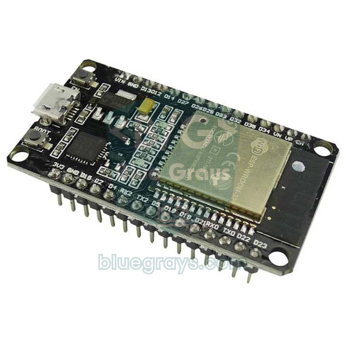
When you upload your sketch and connect a multimeter, you will often see 5–15 mA instead of 10 µA. The problem is not the chip but the extra parts on the board. Most cheap DevKit and NodeMCU-32S boards use an AMS1117 regulator to drop 5 V to 3.3 V, and that regulator alone typically wastes 5 mA even with no load. Add an always-on power LED and the USB-to-serial chip that talks to your computer (CP2102 or CH340). Together they usually come to around 8 mA and drain about 190 mAh a day from the battery even while the ESP32 sleeps, so a 3000 mAh 18650 barely lasts two weeks with such a board. To measure the current, put the multimeter in series between the battery and the circuit and switch to the µA range during sleep; the details are in the how to use a multimeter guide.
| Current source | Current in sleep | Fix |
|---|---|---|
| ESP32 module (deep sleep) | ≈10 µA | Already low, nothing to do |
| AMS1117 regulator | Typically 5 mA (quiescent) | Use an MCP1700 (1.6 µA quiescent) or an HT7333 (around 4 µA) |
| Power LED | 1–3 mA | Remove the LED or its resistor |
| USB-to-serial chip (CP2102, CH340) | Depends on the board, can reach the mA range | Use a board without a USB chip or a bare module |
| 100 kΩ + 100 kΩ battery divider | 21 µA (at 4.2 V) | Use 1 MΩ + 1 MΩ or switch the divider on with a MOSFET only while measuring |
| Sensors that are always powered | From µA to mA, depending on the sensor | Power the sensor from a GPIO or a MOSFET only while measuring |
Your first deep sleep sketch: timer wake-up
- In the Arduino IDE Boards Manager install the esp32 by Espressif Systems package (version 3.1 or later) and select ESP32 Dev Module as the board.
- Upload the sketch below and open the Serial Monitor at 115200 baud.
- The board wakes up every 10 seconds; watch the boot count go up and the wake-up reason print as Timer.
- Press the EN button: the counter goes back to 1, because this is a normal reset, not a wake from deep sleep.
- In your real project set TIME_TO_SLEEP to 600 (10 minutes) or 3600 (1 hour).
1// ESP32 deep sleep: zamanlayıcıyla uyanma ve RTC sayaç / timer wake-up and RTC counter
2#define uS_TO_S_FACTOR 1000000ULL   // 1 saniye = 1.000.000 µs / 1 second = 1,000,000 µs
3#define TIME_TO_SLEEP  10           // uyku süresi, saniye / sleep time in seconds
4
5RTC_DATA_ATTR int bootCount = 0;    // RTC belleğinde, derin uykuda silinmez / in RTC memory, kept in deep sleep
6
7void printWakeupReason() {
8  esp_sleep_wakeup_cause_t cause = esp_sleep_get_wakeup_cause();
9  switch (cause) {
10    case ESP_SLEEP_WAKEUP_TIMER:    Serial.println("Zamanlayici / Timer"); break;
11    case ESP_SLEEP_WAKEUP_EXT0:     Serial.println("ext0 (tek pin / single pin)"); break;
12    case ESP_SLEEP_WAKEUP_EXT1:     Serial.println("ext1 (coklu pin / multiple pins)"); break;
13    case ESP_SLEEP_WAKEUP_TOUCHPAD: Serial.println("Dokunmatik / Touch"); break;
14    default: Serial.printf("Ilk acilis ya da reset / Power-on or reset (%d)\n", (int)cause); break;
15  }
16}
17
18void setup() {
19  Serial.begin(115200);
20  delay(500);                       // Seri Monitör'e zaman tanı / give the Serial Monitor time
21  bootCount++;
22  Serial.printf("Uyanis sayisi / Boot count: %d\n", bootCount);
23  printWakeupReason();
24
25  // Burada sensörü oku, veriyi gönder / read the sensor and send the data here
26
27  esp_sleep_enable_timer_wakeup(TIME_TO_SLEEP * uS_TO_S_FACTOR);   // 10 s sonra uyan / wake after 10 s
28  Serial.println("Derin uyku basliyor / Entering deep sleep");
29  Serial.flush();                   // yazı bitmeden uyuma / finish printing before sleeping
30  esp_deep_sleep_start();           // buradan sonrası çalışmaz / nothing below runs
31}
32
33void loop() {
34  // Derin uykuda loop() hiç çalışmaz / loop() never runs with deep sleep
35}
The heart of the sketch is two lines: esp_sleep_enable_timer_wakeup() sets the wake-up time in microseconds, and esp_deep_sleep_start() sends the chip to sleep immediately; nothing you write after that line ever runs. Do not forget the ULL (64-bit) suffix when calculating the time: 3600 * 1000000 overflows a 32-bit int, the compiler only gives a warning, and the board either wakes at the wrong time or never wakes at all. Serial.flush() waits until the transmit buffer is empty; without it the last lines get cut off. esp_sleep_get_wakeup_cause() tells you why the board woke up and returns no sleep source after the first power-up or a reset. The RTC timer that counts the sleep time runs from an internal RC oscillator of roughly 150 kHz by default. It is not as stable as a crystal and can drift by a few percent with temperature, so in projects where the clock matters it is a good idea to sync the time with NTP when the board wakes.
Keeping counters and readings in RTC memory
If you need to remember something between wakes, put RTC_DATA_ATTR in front of the variable: the compiler places it in the 8 KB RTC SLOW memory, which stays powered in deep sleep, instead of the main RAM. It is ideal for small data such as counters, recent readings, Wi-Fi channel information or the last temperature you sent. This memory is not permanent, though: according to Espressif's documentation, data in RTC memory is re-initialised on every restart except a wake from deep sleep. Swapping the battery, pressing EN, uploading new code or calling ESP.restart() resets the counter. Save settings that must survive a power cut to flash with the Preferences library, but do not do it on every wake, because flash has a limited number of write cycles.
| Event | Normal variable | RTC_DATA_ATTR | Preferences (flash) |
|---|---|---|---|
| Wake from deep sleep | Reset | Kept | Kept |
| EN button or ESP.restart() | Reset | Back to its initial value | Kept |
| Battery removed, power cut | Reset | Lost | Kept |
| New code uploaded | Reset | Lost | Kept (unless flash is erased) |
Used wisely, this memory can multiply your battery life. Connecting to Wi-Fi is the most expensive part of every wake. That is why the sketch below measures the battery voltage every 10 minutes but turns Wi-Fi on only once an hour: six readings pile up in an array in RTC memory and the sixth wake sends them all at once. It also saves the channel and MAC address (BSSID) of the access point in RTC memory, so on the next connection the ESP32 goes straight to that access point without scanning every channel, which noticeably shortens the connection time.
1// RTC belleğinde ölçüm biriktirip saatte bir gönderme / buffer readings in RTC memory, send hourly
2#include <WiFi.h>
3
4const char* SSID = "AgAdi";                       // Wi-Fi adı / Wi-Fi name
5const char* PASS = "Sifre123";                    // Wi-Fi şifresi / Wi-Fi password
6const int BAT_PIN = 35;                           // 1M + 1M bölücünün orta noktası / divider midpoint
7const uint64_t SLEEP_US = 600ULL * 1000000ULL;    // 10 dakika / 10 minutes
8const int BATCH = 6;                              // 6 ölçümde bir gönder / send every 6 readings
9
10RTC_DATA_ATTR float readings[BATCH];              // uykuda korunan ölçümler / readings kept in sleep
11RTC_DATA_ATTR int count = 0;                      // biriken ölçüm sayısı / number of stored readings
12RTC_DATA_ATTR int32_t savedChannel = 0;           // son Wi-Fi kanalı / last Wi-Fi channel
13RTC_DATA_ATTR uint8_t savedBssid[6];              // modemin MAC adresi / access point MAC address
14
15bool connectFast() {
16  WiFi.mode(WIFI_STA);
17  if (savedChannel > 0) {
18    WiFi.begin(SSID, PASS, savedChannel, savedBssid);   // taramadan bağlan / connect without scanning
19  } else {
20    WiFi.begin(SSID, PASS);                             // ilk sefer: normal bağlantı / first time: normal connect
21  }
22  unsigned long start = millis();
23  while (WiFi.status() != WL_CONNECTED) {
24    if (millis() - start > 10000) {                     // 10 s içinde bağlanamazsa vazgeç / give up after 10 s
25      savedChannel = 0;                                 // bir dahaki sefere tara / scan next time
26      return false;
27    }
28    delay(50);
29  }
30  savedChannel = WiFi.channel();
31  memcpy(savedBssid, WiFi.BSSID(), 6);
32  return true;
33}
34
35void setup() {
36  Serial.begin(115200);
37  // Pili Wi-Fi açılmadan önce ölç / measure the battery before Wi-Fi starts
38  float v = analogReadMilliVolts(BAT_PIN) * 2 / 1000.0;   // bölücü gerilimi yarıya indirir / divider halves it
39  readings[count++] = v;
40  Serial.printf("Olcum / Reading %d: %.2f V\n", count, v);
41
42  if (count >= BATCH) {
43    if (connectFast()) {
44      for (int i = 0; i < BATCH; i++) {
45        Serial.printf("Gonder / Send: %.2f V\n", readings[i]);   // burada HTTP ya da MQTT / HTTP or MQTT here
46      }
47      count = 0;
48    } else {
49      for (int i = 1; i < BATCH; i++) readings[i - 1] = readings[i];   // en eskiyi at / drop the oldest
50      count = BATCH - 1;
51    }
52    WiFi.disconnect(true);
53    WiFi.mode(WIFI_OFF);                                // radyoyu kapat / turn the radio off
54  }
55
56  Serial.flush();
57  esp_sleep_enable_timer_wakeup(SLEEP_US);
58  esp_deep_sleep_start();
59}
60
61void loop() {
62}
The battery voltage is halved by a 1 MΩ + 1 MΩ voltage divider and read on GPIO 35, an ADC1 channel. A 100 nF capacitor between the divider midpoint and GND keeps the reading stable even with such a high-impedance divider. Measuring before Wi-Fi starts matters too, because the current drawn while the radio runs makes the battery voltage sag for a moment. If Wi-Fi fails to connect, the oldest reading is dropped and the rest are kept for the next attempt. Shutting the radio down cleanly with WiFi.disconnect(true) and WiFi.mode(WIFI_OFF) before sleeping is also what Espressif recommends. To speed up the connection even more, give the board a static IP with WiFi.config() and skip the DHCP wait. You can find the divider maths in the voltage divider guide and the charging circuit in the TP4056 charging module guide.
Waking up with a button or a PIR sensor: ext0 and ext1
Besides the timer, a signal from the outside world can also wake the ESP32. There are two ways to do it and both only work on RTC GPIO pins: 0, 2, 4, 12–15, 25–27 and 32–39. ext0 watches a single pin and wakes the board when that pin reaches the level you choose (HIGH or LOW); because it keeps the RTC peripherals powered, the internal pull-up and pull-down resistors keep working during sleep. ext1 watches several pins at once through a bit mask. On the classic ESP32, ext1 has two modes: ESP_EXT1_WAKEUP_ANY_HIGH wakes the board when any of the selected pins goes HIGH, and ESP_EXT1_WAKEUP_ALL_LOW wakes it when all of them are LOW at the same time. The ANY_LOW mode, which wakes on any pin going LOW, exists only on the ESP32-S2, S3, C6 and H2. So if you want several buttons to wake a classic ESP32, wire the buttons to 3V3 and give each pin a 10 kΩ pull-down resistor. You can also enable several sources at once; with both the PIR and an hourly timer enabled, for example, the board wakes on whichever comes first.
| Wake-up source | Function | Pins | Note |
|---|---|---|---|
| Timer | esp_sleep_enable_timer_wakeup() | No pin needed | Time in microseconds, 64-bit |
| ext0 | esp_sleep_enable_ext0_wakeup() | One RTC GPIO | Wakes on HIGH or LOW; cannot be combined with touch or ULP |
| ext1 | esp_sleep_enable_ext1_wakeup_io() | Several RTC GPIOs | ANY_HIGH or ALL_LOW; external resistors recommended |
| Touch | touchSleepWakeUpEnable() | T0–T9 (10 pins) | Wakes when the value drops below the threshold; cannot be combined with ext0 |
| ULP coprocessor | esp_sleep_enable_ulp_wakeup() | Depends on the program | Can read sensors while asleep; advanced |
Wiring for the example circuit
| Part | Part pin | ESP32 pin | Note |
|---|---|---|---|
| PIR sensor (HC-SR501 or AM312) | OUT | GPIO 33 | Wakes the board through ext0 |
| PIR sensor | VCC / GND | 5V (HC-SR501) or 3V3 (AM312) / GND | The HC-SR501 needs at least 4.5 V |
| Button A | One leg / other leg | 3V3 / GPIO 25 | 10 kΩ pull-down between GPIO 25 and GND |
| Button B | One leg / other leg | 3V3 / GPIO 26 | 10 kΩ pull-down between GPIO 26 and GND |
| Touch pad or wire | – | GPIO 27 (T7) | Works more reliably when kept short |
| LED + 220 Ω | Anode | GPIO 2 | On most DevKits the onboard blue LED is on this pin too |
| Battery divider (1 MΩ + 1 MΩ) | Midpoint | GPIO 35 | 100 nF between the midpoint and GND |
| 18650 + TP4056 + 3.3 V LDO | LDO output / GND | 3V3 / GND | 470 µF capacitor on the LDO output |
PIR sensor wake-up sketch (ext0)
1// PIR ile uyanma (ext0) / wake on PIR motion (ext0)
2#include "driver/rtc_io.h"
3
4const gpio_num_t PIR_PIN = GPIO_NUM_33;   // RTC GPIO olmalı / must be an RTC GPIO
5const int LED_PIN = 2;                    // uyarı LED'i / alert LED
6
7RTC_DATA_ATTR int motionCount = 0;        // toplam hareket sayısı / total motion count
8
9void setup() {
10  Serial.begin(115200);
11  rtc_gpio_deinit(PIR_PIN);               // pini yeniden normal GPIO yap / turn the pad back into a normal GPIO
12  pinMode(PIR_PIN, INPUT);
13  pinMode(LED_PIN, OUTPUT);
14
15  if (esp_sleep_get_wakeup_cause() == ESP_SLEEP_WAKEUP_EXT0) {
16    motionCount++;
17    Serial.printf("Hareket! / Motion! Toplam / Total: %d\n", motionCount);
18    digitalWrite(LED_PIN, HIGH);          // burada bildirim gönderebilirsin / send a notification here
19    delay(1000);
20    digitalWrite(LED_PIN, LOW);
21  }
22
23  // PIR çıkışı LOW olana kadar bekle, yoksa hemen yeniden uyanır / wait for LOW or it wakes again at once
24  while (digitalRead(PIR_PIN) == HIGH) {
25    delay(100);
26  }
27
28  esp_sleep_enable_ext0_wakeup(PIR_PIN, 1);   // pin HIGH olunca uyan / wake when the pin goes HIGH
29  rtc_gpio_pullup_dis(PIR_PIN);
30  rtc_gpio_pulldown_en(PIR_PIN);              // boştayken LOW tut / keep it LOW while idle
31  Serial.println("Uyku / Sleep");
32  Serial.flush();
33  esp_deep_sleep_start();
34}
35
36void loop() {
37}
After waking up, the sketch first returns the pin to a normal GPIO with rtc_gpio_deinit(). After an ext0 wake the pin stays in RTC mode, and without this line digitalRead() may not work correctly. It counts the motion, flashes the LED and then waits for the PIR output to go back LOW. This wait is essential: if you go to sleep while the output is still HIGH, the board wakes straight away and ends up in a loop that switches on and off several times a second. The HC-SR501 keeps its output HIGH for the time set on its potentiometer, so turn the time potentiometer to the minimum to shorten the wait. Because the HC-SR501 needs at least 4.5 V, choose the small AM312 PIR module, which also runs at 3.3 V, for projects powered by a single 18650. For sensor settings, see the PIR motion sensor guide.
Two-button wake-up sketch (ext1)
1// İki butonla uyanma (ext1) / wake with two buttons (ext1)
2#include "driver/rtc_io.h"
3
4const gpio_num_t BTN_A = GPIO_NUM_25;     // buton A: 3V3'e, 10k pull-down / button A: to 3V3, 10k pull-down
5const gpio_num_t BTN_B = GPIO_NUM_26;     // buton B: 3V3'e, 10k pull-down / button B: to 3V3, 10k pull-down
6const uint64_t WAKE_MASK = (1ULL << BTN_A) | (1ULL << BTN_B);
7
8void setup() {
9  Serial.begin(115200);
10  rtc_gpio_deinit(BTN_A);                 // pinleri normal GPIO'ya döndür / back to normal GPIO
11  rtc_gpio_deinit(BTN_B);
12  pinMode(BTN_A, INPUT);
13  pinMode(BTN_B, INPUT);
14
15  if (esp_sleep_get_wakeup_cause() == ESP_SLEEP_WAKEUP_EXT1) {
16    uint64_t pins = esp_sleep_get_ext1_wakeup_status();   // hangi pin uyandırdı? / which pin woke us?
17    if (pins & (1ULL << BTN_A)) Serial.println("Buton A: isigi ac / Button A: lights on");
18    if (pins & (1ULL << BTN_B)) Serial.println("Buton B: isigi kapat / Button B: lights off");
19  } else {
20    Serial.println("Ilk acilis / First boot");
21  }
22
23  while (digitalRead(BTN_A) == HIGH || digitalRead(BTN_B) == HIGH) {
24    delay(10);                            // butonlar bırakılana kadar bekle / wait until released
25  }
26
27  esp_sleep_enable_ext1_wakeup_io(WAKE_MASK, ESP_EXT1_WAKEUP_ANY_HIGH);  // biri HIGH olunca / any goes HIGH
28  Serial.flush();
29  esp_deep_sleep_start();
30}
31
32void loop() {
33}
After an ext1 wake, esp_sleep_get_ext1_wakeup_status() returns a bit mask that shows which pin woke the board. That lets you give the two buttons different jobs: one turns the light on and the other off, or one sends a reading and the other opens a menu. Because the buttons are wired to 3V3 and the pins are pulled to GND with 10 kΩ, they read LOW when released and HIGH when pressed, which is exactly what ANY_HIGH mode expects. The sketch waits for the buttons to be released before sleeping, otherwise a button that is still held down would wake the board again immediately. If you are on the 2.x or 3.0.x ESP32 Arduino core, which lacks the _io function, write esp_sleep_enable_ext1_wakeup with the same parameters instead of esp_sleep_enable_ext1_wakeup_io. You will find out why the pull-down resistor is needed in the how to connect a button to Arduino guide.
Waking up with a touch (touch wake-up)
Ten ESP32 pins (T0–T9) work as capacitive touch sensors and can detect your finger even in deep sleep. A wire, a strip of copper tape or a PCB pad connected to the pin behaves like a button and can even sit behind a thin plastic or wooden cover. On the classic ESP32 the touchRead() value drops when touched: with a short wire it usually reads 60–80 untouched and 10–20 when touched. Put the wake-up threshold between these two values; the 40 in the example is a good starting point. On the classic ESP32 you can use several touch pins as wake-up sources at once. On the ESP32-S2 and S3, however, only one pin can wake the chip, the value rises when touched and the threshold uses a completely different scale (5000 in Espressif's example). Touch wake-up cannot be combined with ext0; if you also need a button, use ext1. For the pin list and calibration, read the ESP32 touch pins guide.
1// Dokunarak uyandırma: T7 = GPIO 27 / touch wake-up: T7 = GPIO 27
2#define THRESHOLD 40                      // değer bunun altına inince uyanır / wakes when the value drops below this
3
4RTC_DATA_ATTR int touchWakes = 0;
5
6void setup() {
7  Serial.begin(115200);
8  delay(500);
9  if (esp_sleep_get_wakeup_cause() == ESP_SLEEP_WAKEUP_TOUCHPAD) {
10    touchWakes++;
11    Serial.printf("Dokunusla uyanma / Touch wake #%d\n", touchWakes);
12  }
13  // Eşiği ayarlamak için dokunmadan ve dokunarak değeri izle / watch the value untouched and touched
14  Serial.printf("T7 degeri / value: %d\n", (int)touchRead(T7));
15
16  touchSleepWakeUpEnable(T7, THRESHOLD);  // dokunmatikle uyanmayı aç / enable touch wake-up
17  Serial.flush();
18  esp_deep_sleep_start();
19}
20
21void loop() {
22}
ESP32 deep sleep with MicroPython
If you program the ESP32 in MicroPython, you can do the same thing with shorter code. machine.deepsleep(ms) puts the board to sleep for the given number of milliseconds, esp32.wake_on_ext0() makes a pin a wake-up source, and machine.RTC().memory() gives you a byte buffer that survives sleep; on the ESP32 it holds 2048 bytes by default. On waking, main.py runs from the top; machine.reset_cause() tells you whether the board came out of deep sleep and machine.wake_reason() tells you what woke it. RTC pins configured with a pull-up or pull-down keep that setting during sleep. If you are new to MicroPython, start with the MicroPython basics guide.
1import machine, esp32, time
2from machine import Pin
3
4rtc = machine.RTC()
5led = Pin(2, Pin.OUT)
6
7mem = rtc.memory()                            # RTC belleğini oku / read RTC memory
8count = int.from_bytes(mem, "little") if mem else 0
9
10if machine.reset_cause() == machine.DEEPSLEEP_RESET:
11    count += 1
12    if machine.wake_reason() == machine.EXT0_WAKE:
13        print("Butonla uyandi / Woken by button")
14    else:
15        print("Zamanlayiciyla uyandi / Woken by timer")
16else:
17    count = 0
18    print("Ilk acilis / First boot")
19
20rtc.memory(count.to_bytes(4, "little"))       # sayacı sakla / store the counter
21print("Uyanis / Wake:", count)
22
23led.on()                                      # kısa iş: ölç ve gönder / short task: measure and send
24time.sleep_ms(200)
25led.off()
26
27button = Pin(33, Pin.IN, Pin.PULL_DOWN)       # buton GPIO 33 ile 3V3 arasında / button between GPIO 33 and 3V3
28esp32.wake_on_ext0(button, esp32.WAKEUP_ANY_HIGH)   # basınca uyan / wake on press
29machine.deepsleep(60000)                      # 60 s uyu / sleep for 60 s
The Raspberry Pi Pico, on the other hand, has no microamp-level deep sleep like the ESP32. In MicroPython, machine.lightsleep(ms) stops most of the clocks, pauses the CPU and keeps RAM, while machine.deepsleep(ms) resets the board after the same kind of sleep. Even in these modes the board's consumption stays in the milliamp range. So if you want to build a Pico device that runs on batteries for months, cutting the board's power completely between measurements with a power timer such as the TPL5110 gives better results. For the Pico basics, see the what is the Raspberry Pi Pico guide.
A sensor that runs for months on an 18650: battery life calculation
To find the battery life of a device that sleeps and wakes, you first calculate the average current: Average current = (Awake current × Awake time + Sleep current × Sleep time) / Total time. Then you divide the usable battery capacity by that average. You cannot use all of an 18650 labelled 3000 mAh; allowing about 85 %, or 2550 mAh, for the low-voltage cut-off, regulator losses and ageing is realistic. The table below was calculated for a sensor that wakes every 10 minutes, sends data over Wi-Fi and draws an average of 120 mA while connected.
| Scenario | Sleep current | Awake time | Average current | Estimated life |
|---|---|---|---|---|
| DevKit board | 8 mA | 3 s, 120 mA | 8.56 mA | ≈12 days |
| DevKit board, fast connect | 8 mA | 1 s, 120 mA | 8.19 mA | ≈13 days |
| Bare module + MCP1700 + 1 MΩ divider | 15 µA | 3 s, 120 mA | 0.61 mA | ≈173 days (5.7 months) |
| Bare module, fast connect | 15 µA | 1 s, 120 mA | 0.215 mA | ≈494 days (16 months) |
| Bare module, hourly batch upload | 15 µA | 1 s Wi-Fi per hour (120 mA) + 5 × 0.3 s readings (40 mA) | 0.065 mA | ≈4.5 years in theory |
The conclusion is clear: on a development board, shortening the awake time changes almost nothing, because what really drains the battery is the 8 mA in sleep. Once the sleep current drops to microamps, the balance flips and every awake second counts: cutting the Wi-Fi connection from 3 seconds to 1 nearly triples the battery life. When the average current falls below 0.1 mA, the battery's self-discharge starts to matter. A Li-ion cell loses about 2–3 % of its capacity per month, so the theoretical 4.5 years shrinks to around 2 years in practice. To run the numbers with your own values, use the battery life calculator, and read about mAh and Wh in the what does mAh mean guide.
- Pick the right board: boards without a USB chip and power LED, or a bare ESP32 module, draw microamps in sleep.
- Replace the regulator: use an LDO with a quiescent current of a few microamps instead of the AMS1117.
- Power the sensor only while measuring: feed sensors that draw a few mA straight from a GPIO and bigger loads through a P-channel MOSFET; put a pull-up resistor on the MOSFET gate so it stays off during sleep. The details are in the Arduino MOSFET guide.
- Turn Wi-Fi on rarely: collect readings in RTC memory and send them in batches; if you are sending data to another ESP32 nearby, ESP-NOW transmits in far less time because it does not need to join an access point.
- Speed up the connection: with a static IP and a saved channel and BSSID, the Wi-Fi connection often takes less than a second.
- Remove needless waits: delete Serial Monitor output and long delay() lines from the finished project; every awake millisecond comes out of the battery.
- Do not forget the divider and the LEDs: a permanently connected 100 kΩ + 100 kΩ divider draws twice as much current as the sleeping ESP32.
ESP32 deep sleep project ideas
- Battery weather station: measure temperature, humidity and pressure with a BME280 every 10 minutes and send them once an hour to Home Assistant over MQTT.
- Garden moisture sensor: wake up once an hour, measure the soil moisture and send a message to your phone when the soil gets dry.
- Door and window alarm: when the door opens, a reed switch wakes the ESP32 through ext0 and a Telegram bot sends you a message.
- Battery security sensor: build a device that wakes and sends an alert when the PIR detects motion and sleeps for months the rest of the time.
- Touch doorbell: stick copper tape behind a wooden panel; a touch wakes the ESP32, which signals the chime indoors via ESP-NOW.
- Battery temperature logger: measure the temperature of a fridge or an aquarium with a waterproof DS18B20, collect the values in RTC memory and send them a few times a day.
Common mistakes and how to fix them
| Symptom | Cause | Fix |
|---|---|---|
| The board wakes up right after going to sleep | The wake pin is still active (PIR HIGH, button pressed) or floating | Wait for the pin to return to its idle level before sleeping and add a pull-down or pull-up resistor |
| The board does not wake at the expected time | 32-bit overflow in the time calculation (3600 * 1000000) | Add ULL to the constants: 3600ULL * 1000000ULL |
| The counter always starts from 1 | The variable is not RTC_DATA_ATTR or the board was reset | Add RTC_DATA_ATTR; use Preferences for permanent data |
| 5–15 mA measured in sleep | Regulator, power LED, USB chip, divider or sensors | Low-power board or bare module, LDO with low quiescent current |
| Last lines in the Serial Monitor are cut off | The board went to sleep before the buffer was empty | Call Serial.flush() before esp_deep_sleep_start() |
| digitalRead() gives wrong values after waking | The wake pin is still in RTC mode | Call rtc_gpio_deinit() before using the pin |
| A button on GPIO 34–39 does not wake the board | These pins have no internal pull resistors, so the pin floats | Add an external 10 kΩ resistor |
| Code will not upload while the board sleeps | The board has no auto-reset circuit; on the S3 and C3 the native USB port disappears during sleep | Hold BOOT, press and release EN (RESET), then start the upload |
| A relay or LED changes state when the board goes to sleep | Digital pins float (high impedance) in deep sleep | Use a pull resistor or keep the pin level with rtc_gpio_hold_en() |
ESP32 deep sleep is the key to running the same code for months instead of days on a battery: keep the work short, choose the right wake-up source, store the small data you need between wakes in RTC memory and never forget the board's own consumption. If you want to go back to the ESP32 basics, the what is the ESP32 guide is a good start. In the BlueGrays app, the ESP32 Deep Sleep — Battery Saving (OLED + RTC RAM Counter) project lets you try the timer and RTC counter logic from this article on a circuit with an OLED display, with a step-by-step circuit diagram and ready-made code.
Frequently asked questions
How much current does the ESP32 draw in deep sleep?
According to Espressif's datasheet, the ESP32 chip draws about 10 µA in deep sleep with the RTC timer and RTC memory on, and 5 µA in hibernation mode. On development boards such as the DevKit, however, the regulator, power LED and USB-to-serial chip usually push the sleep current to 5–15 mA.
How do you wake an ESP32 from deep sleep?
There are five ways: the RTC timer, a single RTC pin (ext0), several RTC pins (ext1), the touch pins and the ULP coprocessor. You configure the wake-up source before calling esp_deep_sleep_start() and can enable several at the same time; only ext0 and touch wake-up cannot be used together.
Are variables lost in ESP32 deep sleep?
Yes, normal variables are lost, because waking from deep sleep is a restart and setup() runs from the beginning. Variables marked with RTC_DATA_ATTR are stored in RTC memory and kept between wakes, but they return to their initial values after a power cut, a press of the EN button or a new upload.
How long can an ESP32 run on an 18650 battery?
Anywhere from a day to more than a year, depending on the board and how you use it. A DevKit that stays connected to Wi-Fi lasts only 1–2 days on a 3000 mAh 18650, and a DevKit that wakes every 10 minutes lasts about 12 days. A low-power circuit doing the same job with a 15 µA sleep current runs for 5 to 16 months, depending on how long each connection takes.
What is the difference between ESP32 light sleep and deep sleep?
In light sleep the CPU is paused but RAM is kept; when the board wakes, the program continues from the line where it stopped, and the chip draws about 0.8 mA. In deep sleep the RAM is powered down too and consumption drops to 10 µA, but the program starts over on every wake. Light sleep suits pauses of a few seconds, deep sleep suits waits of minutes or hours.
How do you upload code to an ESP32 in deep sleep?
On boards with an auto-reset circuit the upload usually starts without problems, because the uploader resets the chip through the EN pin. If it does not, hold the BOOT button, press and release EN (RESET), then start the upload. On boards with native USB such as the ESP32-S3 and C3 the port disappears during sleep, so this method is often required.
Projects to build after reading this
See all projects
LED Blink with ESP32
Teaches basic GPIO output usage with ESP32. We achieve a blinking effect by turning an LED on and off from a digital pin. ESP32 version of the classic blink project on Arduino UNO; the basic blink commands in the Arduino environment are the same, but the ESP32's pin layout and 3.3 V GPIO levels differ from those of the Arduino UNO.

ESP32 LED Control with Push Button (Push)
The LED lights up when the button is pressed and turns off when released. Shows how the ESP32's digital input pin and internal pull-up resistor are used. The INPUT_PULLUP mode eliminates the need for an external resistor.

ESP32 Deep Sleep — Battery Saving (OLED + RTC RAM Counter)
The ESP32's Deep Sleep mode reduces current consumption to ~10 µA by shutting down the CPU and most peripherals, making it critical for battery-powered IoT devices. In this project, we use three different wake-up sources: a timer (15 seconds), an external pin (EXT0 — button GPIO 33), and touch (T0/GPIO 4). Variables marked with RTC_DATA_ATTR are preserved during deep sleep—the boot counter, timer wake counter, and button wake counter are continuously tracked. On each wake-up, the SSD1306 OLED
ESP32 Motion Alarm System (PIR + Buzzer + LED + Telegram)
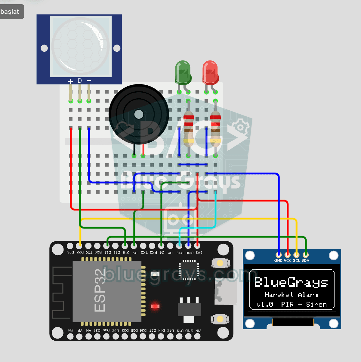
A smart security alarm system that activates the buzzer and LED when the PIR sensor detects motion, while simultaneously sending an instant notification to the owner via Telegram. It includes a 30-second cooldown to limit the frequency of repeated alarms; this mechanism does not validate PIR detections or eliminate false triggers. Suitable for home security, garage monitoring, warehouses, or workrooms. With ESP32-CAM, photo notifications can be added; with the classic ESP32 DevKit V1, text notif

Automatic Lighting with the ESP32 PIR Motion Sensor
In this project, we will use the HC-SR501 PIR motion sensor to detect when someone enters the room and automatically turn on the LED. We will track how long the LED stays on using millis(); each HIGH reading from the sensor will update the last motion time, and the LED will turn off at least 10 seconds after the last HIGH reading. The current code also waits 50 ms in each loop with delay(50), so the application loop is not fully non-blocking. In real-life applications, it can be used for sta

ESP32 DHT22 Temperature and Humidity (with LCD Display)
This project measures ambient temperature and humidity using a DHT22 sensor and displays the data in real time on a 16x2 I2C LCD. Data is read from the sensor using the one-wire protocol via the Adafruit DHT library. This project serves as the foundation for IoT weather stations, smart home automation, or environmental monitoring systems in greenhouses. Communication with the DHT22 is established via the ESP32's GPIO 4 pin.
ESP32 Temperature Data Logger (DHT22 + DS1307 RTC + microSD + OLED)
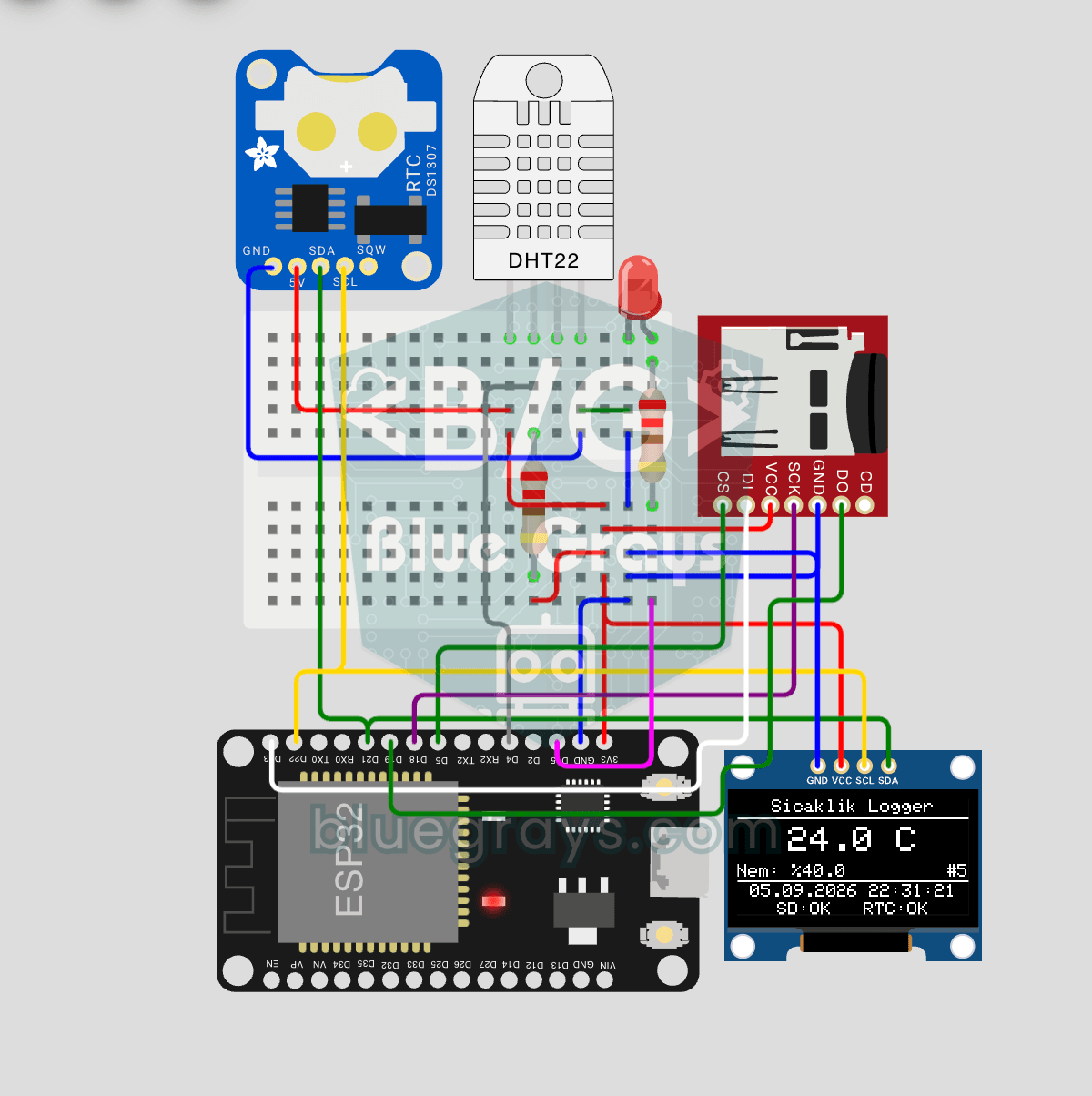
Build a timestamped temperature logger with ESP32! Read DHT22 temperature/humidity every minute, get real-world time from DS1307 RTC, and log to microSD card as CSV. The OLED displays live temperature (large font), humidity percentage, timestamp, and log counter. The /temp_log.csv file on the SD card opens in Excel, Google Sheets, or Python pandas for analysis — perfect for greenhouse monitoring, home/room temperature tracking, laboratory data collection, food storage conditions, or beehiv