
ESP32 RGB LED Web Server: Pick the Color From Your Phone
Build an ESP32 RGB LED web server and set the color from your phone's color picker: common anode/cathode wiring, HEX to RGB, LEDC PWM, gamma and WS2812B.

An ESP32 RGB LED web server lets you change an LED's color without installing any app: the ESP32 serves a small web page, you pick a shade in the color picker that opens in your phone's browser, and the LED switches to it instantly. Three things happen behind the scenes: the browser turns your choice into a HEX code such as #FF8800 and sends it over Wi-Fi, the ESP32 splits that code into three numbers for red, green and blue, and each number becomes a PWM signal generated by the LEDC peripheral.
In this guide you'll learn how to wire a common cathode or common anode RGB LED to the ESP32, which resistor values suit 3.3 V, how to write LEDC code that works on both the 2.x and 3.x ESP32 Arduino core, how to convert HEX to RGB and how gamma correction makes the colors look the way your eye expects. At the end you'll hook the same phone interface up to a WS2812B LED strip without touching a single line of HTML.
How does it work? From the color picker to the LED
- With your phone on the same Wi-Fi network as the ESP32, you open the ESP32's IP address in the browser and it sends back a small HTML page with a color picker.
- The page's <input type="color"> element opens the phone's own color picker and returns the choice in the #ff8800 format.
- A few lines of JavaScript send that value to /set?hex=ff8800; as you slide your finger, new colors go out one after another.
- The ESP32 splits the six digits into three numbers, 255, 136 and 0, and applies gamma correction to each.
- LEDC generates 5 kHz PWM on three pins; the duty cycle sets the brightness of each color and your eye blends the three lights into one shade.
Parts list
- ESP32 DevKit development board (30 or 38 pins)
- One RGB LED (5 mm, common cathode or common anode)
- A 150 Ω resistor for red and 100 Ω resistors for green and blue (three 220 Ω resistors also work if that's what you have)
- Breadboard and a few jumper wires
- A USB cable that carries data
- Optional: WS2812B LED strip, 5 V power supply, 330 Ω resistor and 1000 µF capacitor
Common cathode vs common anode: wiring table
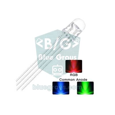
On four-leg RGB LEDs the longest leg is the common one. On a common cathode (CC) LED it goes to GND, and you light a color by driving that color's pin HIGH. On a common anode (CA) LED the common leg goes to the supply voltage and a color lights up when its pin is LOW. If you don't know which one you have, connect the longest leg to GND and another leg to 3V3 through a 150 Ω resistor: if it lights, the LED is common cathode. If not, reverse the connection; if it lights now, it's common anode. On most models the leg order, starting from the flat side, is red, common, green, blue.
| Leg | Common cathode (CC) | Common anode (CA) | Resistor |
|---|---|---|---|
| Red (R) | GPIO 25 | GPIO 25 | 150 Ω |
| Common leg (longest) | GND | 3V3 | None |
| Green (G) | GPIO 26 | GPIO 26 | 100 Ω |
| Blue (B) | GPIO 27 | GPIO 27 | 100 Ω |
| Setting in the code | COMMON_ANODE = false | COMMON_ANODE = true | None |
| Duty cycle for a color at full brightness | 1023 (maximum) | 0 (the code inverts it for you) | None |
The resistor calculation is a simple application of Ohm's law: R = (3.3 V − LED voltage) / current. A red LED needs about 2.0 V; with 150 Ω the current is (3.3 − 2.0) / 150 ≈ 8.7 mA. Green and blue LEDs run at around 2.8 to 3.1 V, so there's very little headroom at 3.3 V; with 100 Ω, 3 to 5 mA flows and the colors look bright enough. With 220 Ω on all three legs the circuit still works, but blue and green are noticeably dimmer and white turns pinkish. To calculate with your own LED's values, use the LED resistor calculator. Don't draw more than 20 mA continuously from an ESP32 pin.
ESP32 LEDC PWM: three channels, 5 kHz, 10-bit
On the ESP32, the equivalent of the Arduino Uno's analogWrite is the LEDC peripheral. The classic ESP32 has 16 independent PWM channels, and you choose the frequency and resolution for each. This project uses 5 kHz and 10 bits: 10 bits means the duty cycle runs from 0 to 1023, which gives much smoother fades than 8 bits, especially in dark shades. 5 kHz is fast enough that neither your eye nor most phone cameras see any flicker. The one thing to watch out for is that the LEDC functions changed in version 3.0 of the ESP32 Arduino core, which is why lots of older code from the internet no longer compiles on a fresh install. The sketches below check the ESP_ARDUINO_VERSION_MAJOR constant and work on both versions. For the basics, see the what is PWM guide.
| Core version | Setup | Writing the value |
|---|---|---|
| 3.x (current) | ledcAttach(pin, 5000, 10) | ledcWrite(pin, duty) |
| 2.x (older) | ledcSetup(channel, 5000, 10) and ledcAttachPin(pin, channel) | ledcWrite(channel, duty) |
Test the wiring first
Making sure the wiring is right before moving on to the web server saves time. Upload the sketch below: the LED should light red, green, blue and white for one second each, then go off for a second. If the colors come in a different order (green instead of red, for example), change the order in the PINS array. If the LED is always on and goes dark exactly on white, you have a common anode LED; set COMMON_ANODE to true.
1// RGB LED bağlantı testi: kırmızı, yeşil, mavi, beyaz, kapalı
2// RGB LED wiring test: red, green, blue, white, off
3const int PINS[3] = {25, 26, 27};       // R, G, B pinleri / R, G, B pins
4const bool COMMON_ANODE = false;        // ortak anot ise true / true for common anode
5const int PWM_FREQ = 5000;              // 5 kHz, titreme yok / 5 kHz, no flicker
6const int PWM_BITS = 10;                // 0-1023
7const int PWM_MAX = (1 << PWM_BITS) - 1;
8
9void pwmSetup() {
10  for (int i = 0; i < 3; i++) {
11#if ESP_ARDUINO_VERSION_MAJOR >= 3
12    ledcAttach(PINS[i], PWM_FREQ, PWM_BITS);   // çekirdek 3.x: pin tabanlı / core 3.x: pin based
13#else
14    ledcSetup(i, PWM_FREQ, PWM_BITS);          // çekirdek 2.x: kanal i / core 2.x: channel i
15    ledcAttachPin(PINS[i], i);
16#endif
17  }
18}
19
20void pwmWrite(int i, int duty) {
21  if (COMMON_ANODE) duty = PWM_MAX - duty;     // ortak anotta mantık ters / logic is inverted for common anode
22#if ESP_ARDUINO_VERSION_MAJOR >= 3
23  ledcWrite(PINS[i], duty);
24#else
25  ledcWrite(i, duty);
26#endif
27}
28
29void setRaw(int r, int g, int b) {      // gamasız ham değer / raw duty, no gamma
30  pwmWrite(0, r);
31  pwmWrite(1, g);
32  pwmWrite(2, b);
33}
34
35void setup() {
36  pwmSetup();
37}
38
39void loop() {
40  setRaw(PWM_MAX, 0, 0);             delay(1000);   // kırmızı / red
41  setRaw(0, PWM_MAX, 0);             delay(1000);   // yeşil / green
42  setRaw(0, 0, PWM_MAX);             delay(1000);   // mavi / blue
43  setRaw(PWM_MAX, PWM_MAX, PWM_MAX); delay(1000);   // beyaz / white
44  setRaw(0, 0, 0);                   delay(1000);   // kapalı / off
45}
Converting a HEX color code to RGB
On the web, colors are written as #RRGGBB: the first two digits are the red value, the next two green and the last two blue, each from 0 to 255 and written in base sixteen (hexadecimal). In #FF8800, FF = 255, 88 = 8 × 16 + 8 = 136 and 00 = 0, so it's full red, some green and no blue: orange. The code does this in two steps: strtol(hex, NULL, 16) turns the six-digit text into a single number (0xFF8800), then bit shifting and a mask pull out the three bytes: (rgb >> 16) & 0xFF for red, (rgb >> 8) & 0xFF for green and rgb & 0xFF for blue.
| HEX | Red | Green | Blue | Color |
|---|---|---|---|---|
| #FF0000 | 255 | 0 | 0 | Red |
| #00FF00 | 0 | 255 | 0 | Green |
| #0000FF | 0 | 0 | 255 | Blue |
| #FF8800 | 255 | 136 | 0 | Orange |
| #800080 | 128 | 0 | 128 | Purple |
| #FFFFFF | 255 | 255 | 255 | White |
| #000000 | 0 | 0 | 0 | Off |
Gamma correction: why do the colors look washed out?
Your eye doesn't perceive brightness linearly: in the dark it notices small changes very well, while in bright light it struggles to tell even big steps apart. That's why a 50 % duty cycle already looks almost fully bright, and the pastel shades you pick on screen turn into washed-out, nearly white colors on the LED. The fix is to apply gamma correction to each channel: output = maximum × (input / 255)^2.2. Screens use the same curve, so after the correction the color on your phone and the color of the LED match much more closely. The table shows how hard the curve squeezes the dark shades, and why 10 bits help:
| Chosen value (0–255) | 8-bit PWM (0–255) | 10-bit PWM (0–1023) |
|---|---|---|
| 16 | 1 | 2 |
| 32 | 3 | 11 |
| 64 | 12 | 49 |
| 128 | 56 | 225 |
| 192 | 137 | 548 |
| 255 | 255 | 1023 |
Main sketch: a web server with a color picker for your phone
The main sketch uses the WebServer library that ships with the ESP32 core, so there's nothing extra to install. Enter your network name and password, upload the sketch and open the Serial Monitor at 115200 baud. After a few seconds you'll see an address like http://192.168.1.45; open it in the browser of a phone on the same Wi-Fi network. The ESP32 only connects to 2.4 GHz networks, and the phone has to be on that same network.
1// ESP32 RGB LED: telefondaki renk seçiciden Wi-Fi ile renk ayarı
2// ESP32 RGB LED: set the colour over Wi-Fi from a colour picker on your phone
3#include <WiFi.h>
4#include <WebServer.h>
5#include <math.h>
6
7const char* WIFI_SSID = "AgAdi";        // Wi-Fi adın / your Wi-Fi name
8const char* WIFI_PASS = "Sifre123";     // Wi-Fi şifren / your Wi-Fi password
9
10const int PINS[3] = {25, 26, 27};       // R, G, B pinleri / R, G, B pins
11const bool COMMON_ANODE = false;        // ortak anot ise true / true for common anode
12const int PWM_FREQ = 5000;              // 5 kHz, titreme yok / 5 kHz, no flicker
13const int PWM_BITS = 10;                // 0-1023, koyu tonlar daha yumuşak / smoother dark tones
14const int PWM_MAX = (1 << PWM_BITS) - 1;
15const float GAMMA = 2.2;                // algısal parlaklık düzeltmesi / perceptual correction
16
17WebServer server(80);
18String currentHex = "000000";           // son seçilen renk / last chosen colour
19
20// Telefonda açılan sayfa / the page opened on the phone
21const char PAGE[] PROGMEM = R"rawliteral(
22<!DOCTYPE html><html><head><meta charset="utf-8">
23<meta name="viewport" content="width=device-width,initial-scale=1">
24<title>ESP32 RGB</title>
25<style>
26body{font-family:sans-serif;text-align:center;background:#111;color:#eee;margin-top:40px}
27input[type=color]{width:200px;height:200px;border:none;background:none}
28button{font-size:18px;padding:10px 20px;margin:6px}
29</style></head><body>
30<h2>ESP32 RGB LED</h2>
31<input type="color" id="c" value="#%HEX%">
32<p id="t">#%HEX%</p>
33<button onclick="pick('#000000')">Kapat / Off</button>
34<button onclick="pick('#ffffff')">Beyaz / White</button>
35<button onclick="pick('#ff8800')">Turuncu / Orange</button>
36<script>
37let busy = false, next = null;
38function send(h) {
39  if (busy) { next = h; return; }
40  busy = true;
41  fetch('/set?hex=' + h.substring(1)).finally(() => {
42    busy = false;
43    if (next) { const n = next; next = null; send(n); }
44  });
45}
46function show(h) { document.getElementById('t').textContent = h; send(h); }
47function pick(h) { document.getElementById('c').value = h; show(h); }
48document.getElementById('c').addEventListener('input', e => show(e.target.value));
49</script></body></html>
50)rawliteral";
51
52void pwmSetup() {
53  for (int i = 0; i < 3; i++) {
54#if ESP_ARDUINO_VERSION_MAJOR >= 3
55    ledcAttach(PINS[i], PWM_FREQ, PWM_BITS);   // çekirdek 3.x: pin tabanlı / core 3.x: pin based
56#else
57    ledcSetup(i, PWM_FREQ, PWM_BITS);          // çekirdek 2.x: kanal i / core 2.x: channel i
58    ledcAttachPin(PINS[i], i);
59#endif
60  }
61}
62
63void pwmWrite(int i, int duty) {
64  if (COMMON_ANODE) duty = PWM_MAX - duty;     // ortak anotta mantık ters / logic is inverted for common anode
65#if ESP_ARDUINO_VERSION_MAJOR >= 3
66  ledcWrite(PINS[i], duty);
67#else
68  ledcWrite(i, duty);
69#endif
70}
71
72int gammaCorrect(int v) {                       // 0-255 -> 0-PWM_MAX
73  return (int)(pow(v / 255.0, GAMMA) * PWM_MAX + 0.5);
74}
75
76void setColor(int r, int g, int b) {
77  pwmWrite(0, gammaCorrect(r));
78  pwmWrite(1, gammaCorrect(g));
79  pwmWrite(2, gammaCorrect(b));
80}
81
82bool isHex6(const String& s) {                  // tam 6 onaltılık hane mi? / exactly 6 hex digits?
83  if (s.length() != 6) return false;
84  for (int i = 0; i < 6; i++) {
85    if (!isxdigit((unsigned char)s[i])) return false;
86  }
87  return true;
88}
89
90void handleRoot() {
91  String page(PAGE);
92  page.replace("%HEX%", currentHex);            // sayfa son renkle açılsın / open with the last colour
93  server.send(200, "text/html", page);
94}
95
96void handleSet() {
97  String hex = server.arg("hex");               // örnek / example: ff8800
98  if (!isHex6(hex)) {
99    server.send(400, "text/plain", "hex?");
100    return;
101  }
102  long rgb = strtol(hex.c_str(), NULL, 16);     // "ff8800" -> 0xFF8800
103  int r = (rgb >> 16) & 0xFF;                   // 255
104  int g = (rgb >> 8) & 0xFF;                    // 136
105  int b = rgb & 0xFF;                           // 0
106  setColor(r, g, b);
107  currentHex = hex;
108  server.send(200, "text/plain", "OK");
109}
110
111void setup() {
112  Serial.begin(115200);
113  pwmSetup();
114  setColor(0, 0, 0);
115  WiFi.mode(WIFI_STA);
116  WiFi.begin(WIFI_SSID, WIFI_PASS);
117  while (WiFi.status() != WL_CONNECTED) {
118    delay(500);
119    Serial.print(".");
120  }
121  WiFi.setSleep(false);                         // daha hızlı yanıt / faster response
122  Serial.println();
123  Serial.print("Telefonda aç / open on your phone: http://");
124  Serial.println(WiFi.localIP());
125  server.on("/", handleRoot);
126  server.on("/set", handleSet);
127  server.begin();
128}
129
130void loop() {
131  server.handleClient();
132}
How the code works
| Part | What it does |
|---|---|
| PAGE | The HTML, CSS and JavaScript sent to the phone; R"rawliteral(...)" lets you write it without escaping quotes |
| input type="color" | Opens the phone's built-in color picker and returns the choice as #rrggbb |
| send() and busy | Sends only one request at a time; of the colors that pile up while you slide, only the latest goes out |
| /set?hex=ff8800 | The request that reaches the ESP32; handleSet() answers it |
| isHex6() | Checks that the text is exactly six hex digits and rejects malformed requests |
| strtol and bit shifting | Turn the text into a number and separate the red, green and blue bytes |
| gammaCorrect() | Maps the 0–255 value to 0–1023 along the gamma 2.2 curve |
| pwmWrite() | Inverts the value for common anode and makes the right ledcWrite call for the core version |
| %HEX% | Shows the last color whenever the page opens, so a second phone also sees the current color |
| WiFi.setSleep(false) | Turns off Wi-Fi power saving so color changes arrive without delay |
The same interface with a WS2812B strip
If you'd rather drive a strip of dozens of LEDs than a single RGB LED, you don't touch the HTML or the web server at all; you only swap the functions that drive the LED. Every WS2812B LED has its own driver chip, so a single data pin is enough. Connect the strip's DIN end to GPIO 13 through a 330 Ω resistor, power the strip from a separate 5 V supply and tie the supply's GND to the ESP32's GND. Each LED draws about 60 mA at full white; a 30-LED strip can reach 1.8 A, which is why the code limits brightness to 80/255. A 1000 µF capacitor across the power terminals protects the LEDs from the inrush current at power-up. With the strip on 5 V, the ESP32's 3.3 V data signal is usually enough; if you see flicker or random colors, add a level shifter such as the 74AHCT125. Strip details are in the WS2812B NeoPixel guide. Put the fragment below in place of the four LED functions in the main sketch and install the Adafruit NeoPixel library from the Library Manager:
1// WS2812B şerit: ana koddaki pwmSetup, pwmWrite, gammaCorrect ve setColor yerine bunu koy
2// WS2812B strip: use this instead of pwmSetup, pwmWrite, gammaCorrect and setColor in the main sketch
3#include <Adafruit_NeoPixel.h>
4
5const int STRIP_PIN = 13;               // DIN, 330 Ω direnç üzerinden / through a 330 Ω resistor
6const int NUM_LEDS = 30;                // şeritteki LED sayısı / number of LEDs on the strip
7Adafruit_NeoPixel strip(NUM_LEDS, STRIP_PIN, NEO_GRB + NEO_KHZ800);
8
9void pwmSetup() {                       // adı aynı, setup() değişmez / same name, setup() stays as is
10  strip.begin();
11  strip.setBrightness(80);              // akımı sınırla / limit the current
12}
13
14void setColor(int r, int g, int b) {
15  strip.fill(strip.gamma32(strip.Color(r, g, b)));   // kütüphanenin gama tablosu / the library's gamma table
16  strip.show();
17}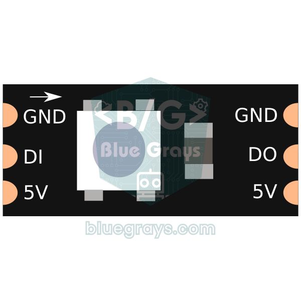
The same conversion in MicroPython (ESP32 and Pico)
If you program your ESP32 or Raspberry Pi Pico in MicroPython, the path from HEX to PWM is the same; the only difference is that the duty cycle is written as 16 bits (0–65535). You can add the function below to your own web server or MQTT code. On a Pico you could use GP11, GP12 and GP13 for red, green and blue, for example.
1# MicroPython (ESP32 ya da Pico): HEX rengi üç PWM kanalına yazar
2# MicroPython (ESP32 or Pico): writes a HEX colour to three PWM channels
3from machine import Pin, PWM
4
5PINS = (25, 26, 27)        # Pico'da örneğin (11, 12, 13) / on a Pico e.g. (11, 12, 13)
6GAMMA = 2.2
7leds = []
8for p in PINS:
9    pwm = PWM(Pin(p))
10    pwm.freq(5000)
11    leds.append(pwm)
12
13def set_hex(color):
14    color = color.lstrip("#")
15    rgb = (int(color[0:2], 16), int(color[2:4], 16), int(color[4:6], 16))
16    for led, v in zip(leds, rgb):
17        led.duty_u16(int(((v / 255) ** GAMMA) * 65535))   # 16 bit görev oranı / 16-bit duty
18
19set_hex("#ff8800")         # turuncu / orange
ESP32 RGB LED project ideas
- Mood lamp: put the RGB LED in a frosted glass jar and switch it to a warm orange from your phone in the evening.
- Notification light: make the LED turn blue when an email or a message arrives; for messaging, see the ESP32 Telegram bot guide.
- Room ambient lighting: apply the same interface to an ordinary 12 V RGB strip with MOSFETs; details are in the RGB LED strip control guide.
- Everyone sees the same color: use WebSocket instead of HTTP so a color picked on one phone shows up instantly on every other open page; the ESP32 WebSocket guide shows how.
- Sunrise alarm: get the time over NTP and, half an hour before you wake up, slowly fade from deep red to white; for the clock, see the ESP32 NTP clock guide.
- Smart home integration: control the color from Home Assistant over MQTT; the steps are in the ESP32 MQTT and Home Assistant guide.
Common mistakes and fixes
| Symptom | Cause | Fix |
|---|---|---|
| You pick red and green lights up | The legs are on different pins | Change the order of the PINS array to match your LED |
| Black makes the LED fully bright and white turns it off | The LED is common anode | Set COMMON_ANODE = true and connect the common leg to 3V3 |
| Blue and green very dim, white looks pink | Resistor too large for 3.3 V | Use 100 Ω or 68 Ω for green and blue |
| 'ledcSetup' was not declared in this scope | Old code on the ESP32 3.x core | Use the #if ESP_ARDUINO_VERSION_MAJOR check from this guide |
| The page won't open | The phone is on another network, the guest network or mobile data | Put the phone on the same 2.4 GHz network as the ESP32 and read the IP again in the Serial Monitor |
| Color changes stutter | Wi-Fi power saving or too many requests | WiFi.setSleep(false) and the busy flag; if the signal is weak, move the ESP32 closer to the router |
Picking a color from your phone makes a first Wi-Fi project that's as educational as it is eye-catching: one circuit shows you a web server, HTTP requests, PWM and gamma correction. In the BlueGrays app, the ESP32 RGB LED Control project and the ESP32 Color Mixer Lamp with three potentiometers walk you through this circuit step by step with a wiring diagram and ready-made code, so you can then carry the idea over to a lamp of your own.
Frequently asked questions
How do I control an RGB LED with an ESP32?
Connect the red, green and blue legs of the RGB LED to three GPIO pins through resistors and the common leg to GND (to 3V3 for common anode). Attach a PWM channel to each pin with LEDC and set each color's brightness by changing the duty cycle. Mixing the three gives any shade you want.
Why doesn't ledcSetup work on ESP32 core 3.0?
The LEDC functions changed in version 3.0 of the ESP32 Arduino core: ledcSetup and ledcAttachPin were removed, ledcAttach(pin, frequency, resolution) replaced them, and ledcWrite now takes the pin instead of the channel. With an #if ESP_ARDUINO_VERSION_MAJOR >= 3 check, the same code compiles on both versions.
How can I tell if my RGB LED is common anode or common cathode?
Connect the longest leg to GND and another leg to 3.3 V through a resistor; if it lights, it's common cathode. If not, reverse the connection; if it lights now, it's common anode. With common anode the code's logic is inverted and a color lights when its pin is LOW.
What resistor should I use for an RGB LED on an ESP32?
At 3.3 V, 150 Ω for red and 100 Ω for green and blue are a good starting point. With 220 Ω on all three legs the LED works, but green and blue stay dim. Don't draw more than 20 mA continuously from a pin.
How do I convert a HEX color to RGB?
In the #RRGGBB format, each pair of digits is the hexadecimal value of one color. In #FF8800, FF = 255 red, 88 = 136 green and 00 = 0 blue. In Arduino code you can turn the text into a number with strtol(hex, NULL, 16) and separate the channels by shifting 16 and 8 bits to the right.
Can I control a WS2812B strip from my phone with an ESP32?
Yes. The web page and the server code stay the same; only the function that writes the color changes to the fill and show calls of the Adafruit NeoPixel library. Power the strip from a separate 5 V supply and connect the grounds together.
Projects to build after reading this
See all projects
LED Blink with ESP32
Teaches basic GPIO output usage with ESP32. We achieve a blinking effect by turning an LED on and off from a digital pin. ESP32 version of the classic blink project on Arduino UNO; the basic blink commands in the Arduino environment are the same, but the ESP32's pin layout and 3.3 V GPIO levels differ from those of the Arduino UNO.

ESP32 RGB LED Control
Unlimited color generation with a single RGB LED instead of 3 separate LEDs. As in Arduino, we make a rainbow transition by setting the R/G/B values with analogWrite(). Color theory (such as red+green=yellow) is seen practically.

ESP32 Color Mixer Light (3 Potentiometers + RGB LED + OLED)
A smart color-mixer lamp: turn 3 potentiometers on the ESP32 and mix any color you like! As you turn the red, green and blue potentiometers, the common-cathode RGB LED changes color instantly. The SSD1306 OLED display shows each channel's 0-255 value, fill bars and the HEX web color code (like #FF8040) live.

ESP32 LED Fade with PWM
Smoothly changing the brightness of the LED from 0 to max, from max to 0. We control PWM with analogWrite() as in Arduino - the same syntax as ESP32 Arduino Core 3.0+ works without problems. Pin definition + pinMode + analogWrite is enough.

ESP32 WS2812B NeoPixel Strip Control
WS2812B (NeoPixel) addressable LEDs are smart RGB LEDs that can be chained and controlled from a single data pin. In this project we drive an 8-LED WS2812B strip with the Adafruit_NeoPixel library and create a smooth rainbow animation. The ESP32's 3.3V logic works with most WS2812B batches; if it gets unstable, we show the fix with a 470Ω series resistor and a 1000µF capacitor. The animation shifts the hue in HSV color space.

ESP32 Asynchronous Web Server (with IP Display on LCD)
In this project, we’re turning the ESP32 into an asynchronous web server that you can control from your phone or computer on the same Wi-Fi network. Thanks to the ESPAsyncWebServer library, the server can process multiple requests simultaneously (unlike the classic WebServer.h, which blocks on a single request). You’ll be able to open the ESP32’s IP address in a browser and click the ON/OFF buttons (the /on and /off routes) to turn the LED connected to GPIO 5 on and off.

ESP32 WebSocket Counter (2 Buttons + LCD + Real-Time Web)
In this project, two buttons wired to the ESP32 (GPIO 5 counts up, GPIO 4 counts down) change a counter. The value updates instantly both on a 16x2 I2C LCD and, through the WebSocket support of ESPAsyncWebServer, in every connected browser without reloading the page. Instead of HTTP polling a single persistent connection is used, and the ESP32 sends the new value to everyone with ws.textAll().

ESP32 LED Brightness Control with a Potentiometer (Analog → PWM)
In this project, we control the brightness of an LED analogically using a potentiometer. The ESP32's ADC pin reads the 0-3.3V voltage from the potentiometer, and this value is then converted into a PWM (Pulse Width Modulation) signal and sent to the LED. As a result, as you turn the potentiometer, the LED gradually brightens and dims. With Arduino Core 3.0+, analogWrite() can be used directly; on the ESP32-S2/S3, the ADC resolution is fixed at 12-bit.