
Arduino RGB LED Strip Control: 12 V Color Mixing with MOSFETs
Arduino RGB LED strip control: drive a 12 V 5050 strip with IRLZ44N MOSFETs, three-channel PWM, color fades, pot color picker, plus ESP32 and Pico code.

Arduino RGB LED strip control means driving the red, green and blue channels of a 12 V non-addressable 5050 RGB strip with three separate PWM signals to get any color you want. Arduino pins can't handle the amps a strip draws or 12 V, so each channel gets a MOSFET: the Arduino only sends a 5 V signal to the MOSFET's gate, and the MOSFET carries the real current. That way a small microcontroller can safely control meters of strip.
In this guide you'll learn the inside of a 5050 strip, how to choose the right MOSFET, the wiring and the power supply calculation. Then you'll mix colors with an Arduino Uno, build a millis()-based smooth color fade and pick hue and brightness with potentiometers, and run the same circuit with the ESP32's LEDC unit and MicroPython PWM on the Raspberry Pi Pico. You'll also find how the strip differs from WS2812B, and fixes for the most common mistakes at the end.
What is an RGB LED strip and how does it work?
In a non-addressable RGB strip, each 5050 SMD package contains three separate LED chips: red, green and blue. The strip is made of 12 V segments connected in parallel, each with three LEDs and one current-limiting resistor per color; the total forward voltage of the three series LEDs is about 6–9 V depending on color, and the resistor takes the rest. The strip has four connections: a common positive (+12V) plus R, G and B. So the strip is common anode: to light a color, you pull that color's line to GND. The whole strip shows one color at a time; you can't light LEDs individually in different colors. You set the color with each channel's PWM duty cycle: red and green fully on gives yellow, all three fully on gives a near-white light.
| Feature | 30 LED/m strip | 60 LED/m strip |
|---|---|---|
| LED type | 5050 SMD (5.0 × 5.0 mm, 3 chips) | 5050 SMD (5.0 × 5.0 mm, 3 chips) |
| Operating voltage | 12 V DC | 12 V DC |
| Power (full white) | About 7.2 W/m | About 14.4 W/m |
| Current (full white) | About 0.6 A/m | About 1.2 A/m |
| Current per channel | About 0.2 A/m | About 0.4 A/m |
| Cutting interval | Every 3 LEDs (10 cm) | Every 3 LEDs (5 cm) |
| Connections | +12V, R, G, B | +12V, R, G, B |
RGB strip vs WS2812B: what's the difference?
Both strips give RGB light, but they're controlled in completely different ways. A non-addressable strip is like a lamp: you set the color of the whole strip by changing the brightness of three channels. In a WS2812B NeoPixel strip, every LED has a tiny driver chip inside, and you can send a different color to each LED over a single data line. The table below helps you decide which to choose:
| Feature | 12 V RGB strip (5050) | WS2812B strip |
|---|---|---|
| Control | Whole strip, one color | Each LED its own color |
| Supply | 12 V (24 V versions exist too) | 5 V |
| Wiring | 4 wires: +12V, R, G, B | 3 wires: 5V, DIN, GND |
| Driver circuit | One MOSFET per channel | Not needed, one data pin is enough |
| Code | analogWrite / PWM | FastLED or Adafruit NeoPixel library |
| Current (60 LED/m, full white) | About 1.2 A/m (12 V) | About 3.6 A/m (5 V) |
| Voltage drop | Usually fine up to 5 m | Long strips need power injection at several points |
| Effects | Solid color, fades, breathing | Chasing lights, rainbow, animations |
| Price | Cheap | More expensive |
Why do you need a MOSFET, and which one should you choose?
An Arduino Uno pin is designed to supply about 20 mA (absolute limit 40 mA), yet a single channel of a 5 m, 60 LED/m strip can draw 2 A. On top of that, the strip runs on 12 V. An N-channel MOSFET solves this as a low-side switch: the Drain goes to the strip's color line, the Source goes to GND, and the voltage on the Gate switches the MOSFET on and off. The key point is to pick a logic-level MOSFET; standard MOSFETs like the IRF520 or IRF540N want about 10 V to turn fully on, and at 5 V they stay half-open and get hot. The power dissipated in a MOSFET is P = I² × Rds(on): for 2 A and 0.025 Ω that's 2 × 2 × 0.025 = 0.1 W, so no heatsink is needed. For the basics, check out Using a MOSFET with Arduino.
| MOSFET | Gate voltage | Rds(on) | Suitability |
|---|---|---|---|
| IRLZ44N | Logic level, fully on at 4–5 V | 0.025 Ω (at 5 V) | Ideal for Uno and Nano; at 3.3 V only for short strips |
| IRLB8721 | Turns on well at 3.3 V too | About 0.009 Ω (at 4.5 V) | One of the best choices for ESP32 and Pico |
| AO3400 (SMD) | Turns on at 2.5 V | About 0.03 Ω (at 4.5 V) | Small boards, 2–3 A per channel |
| IRF520 / IRF540N | Wants about 10 V | High at 5 V | Not recommended, gets hot |
Circuit diagram and wiring table
You build the same small circuit three times, once per color channel. Hold the IRLZ44N with the printed side facing you and the pins from left to right are Gate, Drain, Source; you can also check the pin order with the transistor tool. Put a 220 Ω resistor between the Gate and the board pin; it limits the surge current drawn from the pin while the gate capacitance charges. Also add a 10 kΩ pull-down resistor between the Gate and GND; it stops the MOSFET from turning on by itself and lighting the strip randomly when the pins float during power-up or code upload. The most important rule: the 12 V adapter's negative must be joined to the board's GND, otherwise the gate signal has no reference. We cover this in detail in the common GND article.
| Connection | Arduino Uno | ESP32 | Raspberry Pi Pico |
|---|---|---|---|
| Red MOSFET Gate (via 220 Ω) | D9 | GPIO 25 | GP11 |
| Green MOSFET Gate (via 220 Ω) | D10 | GPIO 26 | GP12 |
| Blue MOSFET Gate (via 220 Ω) | D11 | GPIO 27 | GP13 |
| MOSFET Drain pins | Strip R, G, B wires | Strip R, G, B wires | Strip R, G, B wires |
| MOSFET Source pins | GND | GND | GND |
| Hue potentiometer (middle pin) | A0 | GPIO 34 | GP26 (ADC0) |
| Brightness potentiometer (middle pin) | A1 | Not used | Not used |
| Potentiometer outer pins | 5V and GND | 3V3 and GND | 3V3 and GND |
| 12 V adapter negative | GND | GND | GND |
| Strip +12V wire | Adapter positive | Adapter positive | Adapter positive |
Power calculation: which adapter should you buy?
To choose the adapter, first calculate the strip's current at full white: I = meters × A/m. A 5 m, 60 LED/m strip draws 5 × 1.2 = 6 A; the power is P = V × I = 12 × 6 = 72 W. Always choose an adapter with about 20% headroom: in this example a 12 V 8 A (96 W) supply is right. A 2 m, 30 LED/m strip draws 1.2 A, so a 12 V 2 A adapter is enough. Choose the wire for the current too; above 5 A, use wire of at least 0.75 mm² instead of jumper wires. If you want to power the board from the same adapter, the Arduino Uno's power jack or Vin pin accepts 12 V and works fine under light loads. On ESP32 dev boards and the Pico, don't connect 12 V directly; the Pico's VSYS input accepts 5.5 V at most. For these boards, the cleanest solution is to step 12 V down to 5 V with an LM2596 buck converter and feed it to the 5V pin on the ESP32 and VSYS on the Pico. You can check the calculations with the Ohm's Law calculator and read calculating electrical power for details.
Step-by-step setup
- Build the whole circuit before plugging the adapter into the wall; don't change connections while the circuit is powered.
- Solder four wires to the strip's solder pads or use a ready-made connector; connect the +12V wire to the adapter's positive.
- Place the three MOSFETs and connect their Source pins to the common GND rail. Breadboard rails are suitable for about 1 A; for strips drawing several amps, make the current path with soldered joints or a terminal block.
- Connect each MOSFET's Drain to the matching color wire of the strip (R, G, B).
- Connect the Gate pins to D9, D10 and D11 through 220 Ω resistors; add a 10 kΩ resistor between each Gate and GND.
- Connect the 12 V adapter's negative to the Arduino's GND pin to create the common ground.
- Connect the Arduino to your computer by USB, upload the first code, then plug in the adapter.
- Check that each color lights up on its own; if the wrong color lights, swap the pin numbers in the code.
First code: color mixing with Arduino
After building the circuit, the safest start is to test each channel one by one. The code below uses the Uno's PWM pins 9, 10 and 11 and shows six different colors in turn with the setColor() function. If you're curious about how PWM works, see What is PWM.
1const int PIN_R = 9;    // kırmızı MOSFET kapısı / red MOSFET gate
2const int PIN_G = 10;   // yeşil MOSFET kapısı / green MOSFET gate
3const int PIN_B = 11;   // mavi MOSFET kapısı / blue MOSFET gate
4
5void setColor(uint8_t r, uint8_t g, uint8_t b) {
6  analogWrite(PIN_R, r);   // 255 = tam parlak, 0 = sönük / 255 = full, 0 = off
7  analogWrite(PIN_G, g);
8  analogWrite(PIN_B, b);
9}
10
11void setup() {
12  pinMode(PIN_R, OUTPUT);
13  pinMode(PIN_G, OUTPUT);
14  pinMode(PIN_B, OUTPUT);
15  setColor(0, 0, 0);       // başlangıçta kapalı / off at start
16}
17
18void loop() {
19  setColor(255, 0, 0);     delay(1000);   // kırmızı / red
20  setColor(0, 255, 0);     delay(1000);   // yeşil / green
21  setColor(0, 0, 255);     delay(1000);   // mavi / blue
22  setColor(255, 120, 0);   delay(1000);   // turuncu / orange
23  setColor(160, 0, 255);   delay(1000);   // mor / purple
24  setColor(255, 255, 255); delay(1000);   // beyaz / white
25}
There's an important difference here: when you connect a single common-anode RGB LED straight to a pin, the logic is inverted (255 turns it off), but in a MOSFET circuit analogWrite(pin, 255) turns the MOSFET fully on and lights the color at full brightness; 0 turns it off. On the Uno, pins 9 and 10 are tied to Timer1 and pin 11 to Timer2, and all three run at about 490 Hz; at this frequency your eye doesn't notice flicker. However, tone() uses Timer2, so it breaks PWM on pin 11, and the Servo library disables PWM on pins 9 and 10. If your project has a buzzer or servo, plan the pins accordingly. Also, the brightness of the strip's colors isn't equal; if white looks bluish, you can balance it by lowering the blue channel to around 200.
Slow color fade: a color wheel with millis()
To make the strip drift smoothly through all colors, we use a color wheel: a hue value from 0–767 is split into three regions. In the first 256 steps red falls and green rises, in the next 256 it goes from green to blue, and in the last section from blue to red. Because the two channels always add up to 255, the colors flow into each other without jumps. Since we use millis() instead of delay(), loop() can also do other work such as reading buttons or measuring sensors. Our eyes don't perceive brightness linearly: small changes at low values are very noticeable, while those at high values are hard to see. That's why the gamma8() function in the code scales the value by its square (v × v / 255) and makes transitions in dim light look more natural. If you increase STEP_MS, the full cycle gets longer; at 15 ms one cycle takes about 11.5 seconds.
1const int PIN_R = 9;    // kırmızı / red
2const int PIN_G = 10;   // yeşil / green
3const int PIN_B = 11;   // mavi / blue
4
5const unsigned long STEP_MS = 15;   // 768 x 15 ms = yaklaşık 11,5 s / about 11.5 s per cycle
6unsigned long lastStep = 0;
7int hue = 0;                        // renk tonu 0-767 / hue 0-767
8
9uint8_t gamma8(uint8_t v) {
10  return (uint16_t)v * v / 255;     // basit gama düzeltmesi / simple gamma correction
11}
12
13void setColor(uint8_t r, uint8_t g, uint8_t b) {
14  analogWrite(PIN_R, gamma8(r));
15  analogWrite(PIN_G, gamma8(g));
16  analogWrite(PIN_B, gamma8(b));
17}
18
19void wheel(int h) {
20  uint8_t p = h % 256;
21  if (h < 256)      setColor(255 - p, p, 0);   // kırmızı -> yeşil / red -> green
22  else if (h < 512) setColor(0, 255 - p, p);   // yeşil -> mavi / green -> blue
23  else              setColor(p, 0, 255 - p);   // mavi -> kırmızı / blue -> red
24}
25
26void setup() {
27  pinMode(PIN_R, OUTPUT);
28  pinMode(PIN_G, OUTPUT);
29  pinMode(PIN_B, OUTPUT);
30}
31
32void loop() {
33  if (millis() - lastStep >= STEP_MS) {
34    lastStep = millis();
35    wheel(hue);
36    hue = (hue + 1) % 768;
37  }
38  // burada buton ya da sensör okuyabilirsin / you can read buttons or sensors here
39}
Choosing color and brightness with potentiometers
Two potentiometers are enough to pick the color by hand: the one on A0 sets the hue (0–767) and the one on A1 sets the overall brightness (0–255). Since analogRead() returns 0–1023, we scale it to the range we want with map(). Brightness is applied by multiplying each channel value by bri / 255, so the light dims while the hue is preserved. You can also set R, G and B directly with three separate potentiometers, but a single-knob color wheel is far more intuitive and lets you reach every saturated color except white.
1const int PIN_R = 9;
2const int PIN_G = 10;
3const int PIN_B = 11;
4const int POT_HUE = A0;   // renk tonu / hue
5const int POT_BRI = A1;   // parlaklık / brightness
6
7void setup() {
8  pinMode(PIN_R, OUTPUT);
9  pinMode(PIN_G, OUTPUT);
10  pinMode(PIN_B, OUTPUT);
11}
12
13void loop() {
14  int hue = map(analogRead(POT_HUE), 0, 1023, 0, 767);
15  int bri = map(analogRead(POT_BRI), 0, 1023, 0, 255);
16
17  uint8_t r, g, b;
18  uint8_t p = hue % 256;
19  if (hue < 256)      { r = 255 - p; g = p;       b = 0; }       // kırmızı -> yeşil / red -> green
20  else if (hue < 512) { r = 0;       g = 255 - p; b = p; }       // yeşil -> mavi / green -> blue
21  else                { r = p;       g = 0;       b = 255 - p; } // mavi -> kırmızı / blue -> red
22
23  analogWrite(PIN_R, (uint16_t)r * bri / 255);   // parlaklığı uygula / apply brightness
24  analogWrite(PIN_G, (uint16_t)g * bri / 255);
25  analogWrite(PIN_B, (uint16_t)b * bri / 255);
26  delay(20);
27}
Controlling an RGB strip with the ESP32 (LEDC)
The ESP32 uses its hardware LEDC unit for PWM; you choose the frequency and resolution yourself. 5 kHz and 8 bits give both a flicker-free light and the familiar 0–255 range. In Arduino core 3.x you use ledcAttach(pin, frequency, resolution) and ledcWrite(pin, value), while in 2.x you first set up a channel with ledcSetup(), attach it to a pin with ledcAttachPin(), and ledcWrite() writes to the channel; the code below supports both versions with #if. Because the ESP32's pins output 3.3 V, it's important to pick a MOSFET with a low gate voltage, such as the IRLB8721 in the table. We connected the potentiometer to GPIO 34, an ADC1 pin that works fine even with Wi-Fi on; the ADC is 12-bit so values run from 0–4095, and eight readings are averaged to reduce noise. For the board's basics, see What is the ESP32.
1const int PIN_R = 25;       // kırmızı MOSFET kapısı / red MOSFET gate
2const int PIN_G = 26;       // yeşil / green
3const int PIN_B = 27;       // mavi / blue
4const int POT_HUE = 34;     // ADC1, yalnız giriş / ADC1, input only
5const int PWM_FREQ = 5000;  // 5 kHz, titreşimsiz / flicker-free
6const int PWM_RES = 8;      // 8 bit: 0-255
7
8void setColor(uint8_t r, uint8_t g, uint8_t b) {
9#if ESP_ARDUINO_VERSION_MAJOR >= 3
10  ledcWrite(PIN_R, r);      // core 3.x: pine yaz / write to pin
11  ledcWrite(PIN_G, g);
12  ledcWrite(PIN_B, b);
13#else
14  ledcWrite(0, r);          // core 2.x: kanala yaz / write to channel
15  ledcWrite(1, g);
16  ledcWrite(2, b);
17#endif
18}
19
20void setup() {
21#if ESP_ARDUINO_VERSION_MAJOR >= 3
22  ledcAttach(PIN_R, PWM_FREQ, PWM_RES);
23  ledcAttach(PIN_G, PWM_FREQ, PWM_RES);
24  ledcAttach(PIN_B, PWM_FREQ, PWM_RES);
25#else
26  ledcSetup(0, PWM_FREQ, PWM_RES);
27  ledcSetup(1, PWM_FREQ, PWM_RES);
28  ledcSetup(2, PWM_FREQ, PWM_RES);
29  ledcAttachPin(PIN_R, 0);
30  ledcAttachPin(PIN_G, 1);
31  ledcAttachPin(PIN_B, 2);
32#endif
33  analogReadResolution(12);  // 0-4095
34  setColor(0, 0, 0);
35}
36
37void loop() {
38  long sum = 0;
39  for (int i = 0; i < 8; i++) {
40    sum += analogRead(POT_HUE);   // 8 okumayı topla / sum 8 readings
41  }
42  int hue = map(sum / 8, 0, 4095, 0, 767);
43  uint8_t p = hue % 256;
44  if (hue < 256)      setColor(255 - p, p, 0);   // kırmızı -> yeşil / red -> green
45  else if (hue < 512) setColor(0, 255 - p, p);   // yeşil -> mavi / green -> blue
46  else                setColor(p, 0, 255 - p);   // mavi -> kırmızı / blue -> red
47  delay(20);
48}
MicroPython code with the Raspberry Pi Pico
On the Pico, every GPIO pin can produce PWM, and duty_u16() takes a value from 0–65535. In the code we scale 0–255 color values to that range by multiplying by 257 (255 × 257 = 65535). The potentiometer is on GP26 (ADC0); read_u16() also returns 0–65535, so it converts easily to a hue value. GP12 and GP13 share the same PWM slice (slice 6); since we give both the same frequency there's no problem, but if you try to set different frequencies, the last setting affects both. Because the Pico runs at 3.3 V, the MOSFET advice we gave for the ESP32 applies here too. For setup, read What is the Raspberry Pi Pico.
1from machine import Pin, PWM, ADC
2import time
3
4pins = (11, 12, 13)                      # R, G, B MOSFET kapıları / gates
5leds = []
6for p in pins:
7    pwm = PWM(Pin(p))
8    pwm.freq(1000)                       # 1 kHz PWM
9    pwm.duty_u16(0)                      # başlangıçta kapalı / off at start
10    leds.append(pwm)
11
12pot = ADC(26)                            # GP26 = ADC0
13
14def set_color(r, g, b):
15    # 0-255 değerini 0-65535'e çevir / convert 0-255 to 0-65535
16    leds[0].duty_u16(r * 257)
17    leds[1].duty_u16(g * 257)
18    leds[2].duty_u16(b * 257)
19
20def wheel(hue):
21    p = hue % 256
22    if hue < 256:
23        return 255 - p, p, 0             # kırmızı -> yeşil / red -> green
24    elif hue < 512:
25        return 0, 255 - p, p             # yeşil -> mavi / green -> blue
26    return p, 0, 255 - p                 # mavi -> kırmızı / blue -> red
27
28while True:
29    hue = pot.read_u16() * 767 // 65535  # 0-767 ton / hue
30    set_color(*wheel(hue))
31    time.sleep_ms(20)
RGB LED strip project ideas
- Music-reactive ambient light: change the strip's color and brightness to the rhythm of music with a sound sensor; details in the music-reactive LED article.
- Remote-controlled TV backlight: change color and brightness from the couch with an IR receiver and remote.
- Motion-activated stair light: when a PIR sensor detects someone, fade the strip on slowly and switch it off after a while.
- Automatic night light: when an LDR senses it's getting dark, light a warm orange at low brightness.
- Phone control: set up a web server on the ESP32 and use a color picker from your browser.
- Sunrise alarm: starting 20 minutes before your wake-up time, slowly fade the strip from dark red to white.
Common mistakes and how to fix them
| Symptom | Likely cause | Fix |
|---|---|---|
| The strip doesn't light at all | No common GND or the +12V wire isn't connected | Connect the adapter negative to the board's GND and check the strip's +12V wire |
| One color is always on no matter what the code says | MOSFET Drain and Source are swapped or the MOSFET is burnt out | Check the pin order (G-D-S) and replace the MOSFET if needed |
| The strip flashes by itself at power-up | No Gate pull-down resistor | Add 10 kΩ between each Gate and GND |
| The MOSFET gets very hot | Not a logic-level MOSFET or insufficient gate voltage at 3.3 V | Use a logic-level MOSFET such as the IRLZ44N or IRLB8721 |
| Colors are mixed up (green lights instead of red) | Strip labels or wire order are different | Swap the PIN_R, PIN_G, PIN_B values in the code |
| The end of the strip looks yellowish and dim | Voltage drop on a long strip | Power strips longer than 5 m from both ends and use thicker wire |
| The board resets or restarts | Adapter too weak, voltage sagging | Use a more powerful adapter and power the board from a separate regulator |
| Flicker or lines on camera | Low PWM frequency | Raise the frequency to 1–5 kHz on the ESP32 and Pico |
A non-addressable RGB strip with three MOSFETs and three PWM pins is the most practical way to add a powerful, cheap layer of light to your room, desk or project. If you want to control every LED individually, WS2812B can be your next step. In the BlueGrays app you can explore RGB LED color mixing, smooth color fades, an ESP32 color mixer lamp and a Pico RGB color cycle project, step by step with circuit diagrams and code.
Frequently asked questions
Can an RGB LED strip be connected directly to an Arduino?
No. A 12 V strip can draw more than an amp per meter, while an Arduino pin can supply only about 20 mA and works at 5 V. You need to drive the strip through a logic-level MOSFET for each color channel; the Arduino only sends a PWM signal to the MOSFET's gate.
Which MOSFET should I use for a 12 V LED strip?
For the 5 V Arduino Uno and Nano, the IRLZ44N is a common and suitable choice. On 3.3 V boards like the ESP32 and Raspberry Pi Pico, MOSFETs that turn fully on at a low gate voltage, such as the IRLB8721 or AO3400, work better. The IRF520 and IRF540N don't turn fully on at 5 V, so they get hot.
How many amps does a 5 meter RGB LED strip draw?
A 60 LED/m 5050 strip draws about 1.2 A per meter at full white; 5 meters is about 6 A and 72 W. For a 30 LED/m strip these values are halved. Choose the adapter with 20% headroom; for 6 A, a 12 V 8 A adapter is right.
What is the difference between an RGB LED strip and WS2812B?
On a non-addressable RGB strip all LEDs show the same color at once and it's driven with three MOSFETs. On a WS2812B each LED has its own driver chip and you send a different color to each one from a single data pin. WS2812B is ideal for chasing effects, while the RGB strip is ideal for cheap, powerful plain lighting.
Where can you cut an RGB LED strip?
12 V strips work in segments of three LEDs and can only be cut at the cut marks on the copper pads; that spacing is 5 cm on 60 LED/m and 10 cm on 30 LED/m. If you cut anywhere else, that segment won't light. You can reconnect the piece you cut by soldering wires to the pads or using a snap-on connector.
Can I power the Arduino from the strip's 12 V adapter?
You can power the Arduino Uno from the power jack or Vin pin with 12 V; the on-board regulator handles this under light loads. On ESP32 dev boards and the Raspberry Pi Pico, you need to step 12 V down to 5 V with a buck converter such as the LM2596. In every case the adapter's negative must be connected to the board's GND.
Projects to build after reading this
See all projects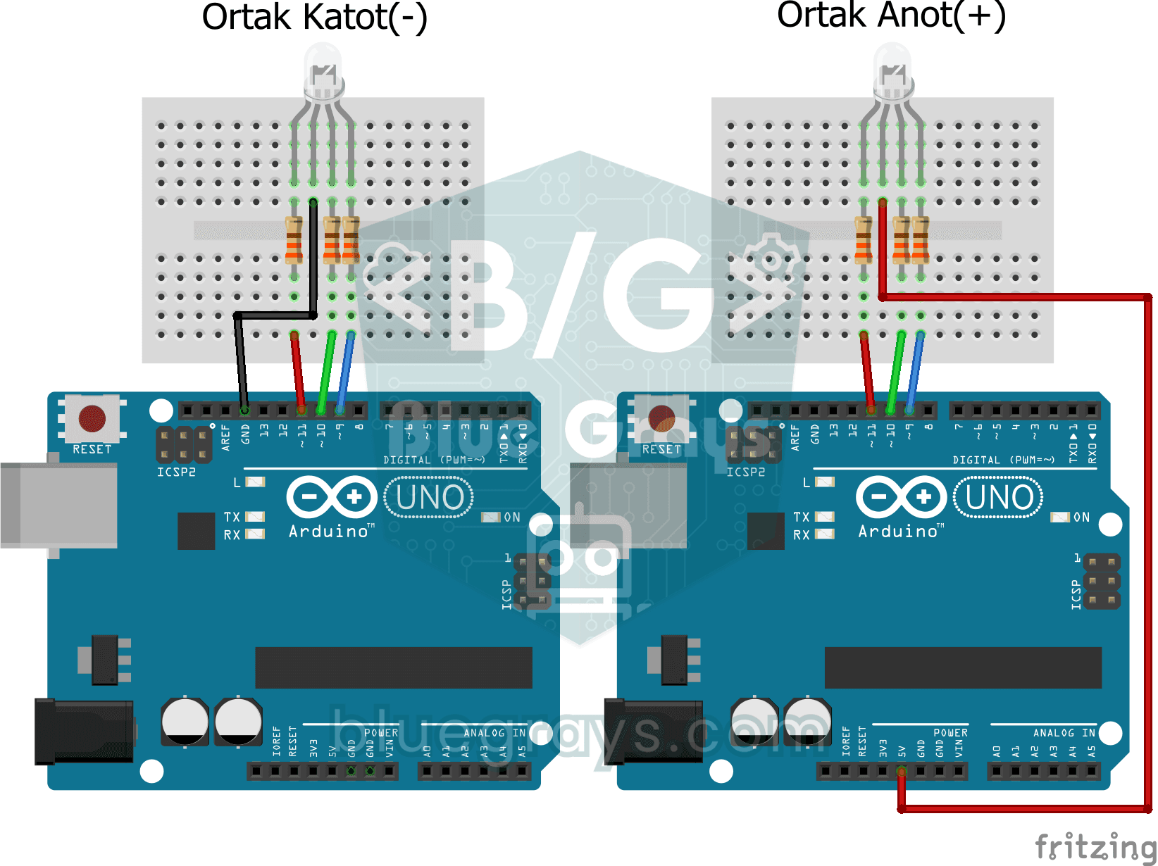
Using an RGB LED
Three colours hide inside a single LED: the RGB LED lights up red, then green, then blue, each colour on for half a second and off for half a second, before the cycle starts again.
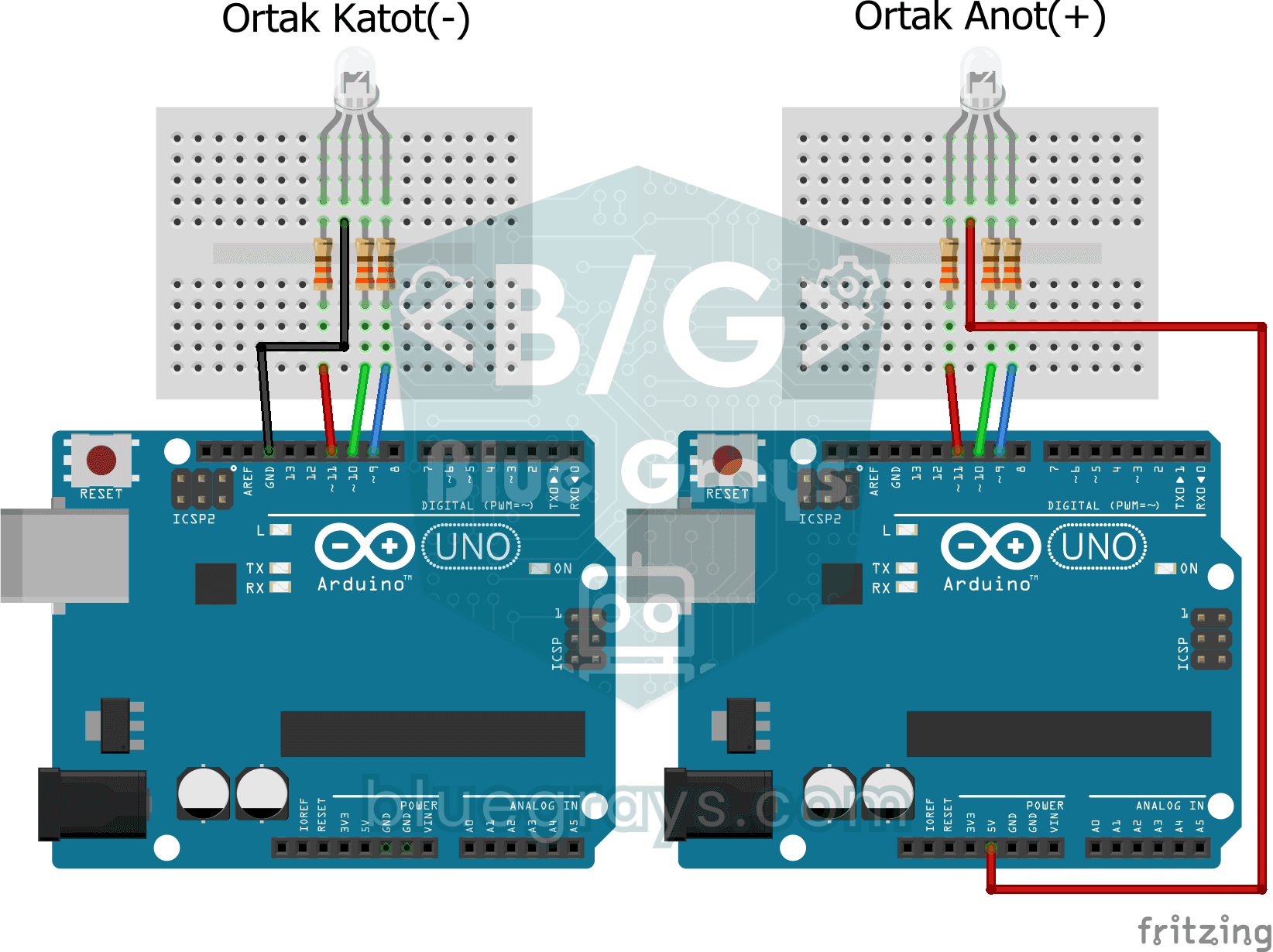
Smooth Color Transition with RGB Led
A single RGB LED drifts slowly from red to green, green to blue and back to red, looping through the rainbow without ever stopping.

ESP32 RGB LED Control
Unlimited color generation with a single RGB LED instead of 3 separate LEDs. As in Arduino, we make a rainbow transition by setting the R/G/B values with analogWrite(). Color theory (such as red+green=yellow) is seen practically.

ESP32 Color Mixer Light (3 Potentiometers + RGB LED + OLED)
A smart color-mixer lamp: turn 3 potentiometers on the ESP32 and mix any color you like! As you turn the red, green and blue potentiometers, the common-cathode RGB LED changes color instantly. The SSD1306 OLED display shows each channel's 0-255 value, fill bars and the HEX web color code (like #FF8040) live.
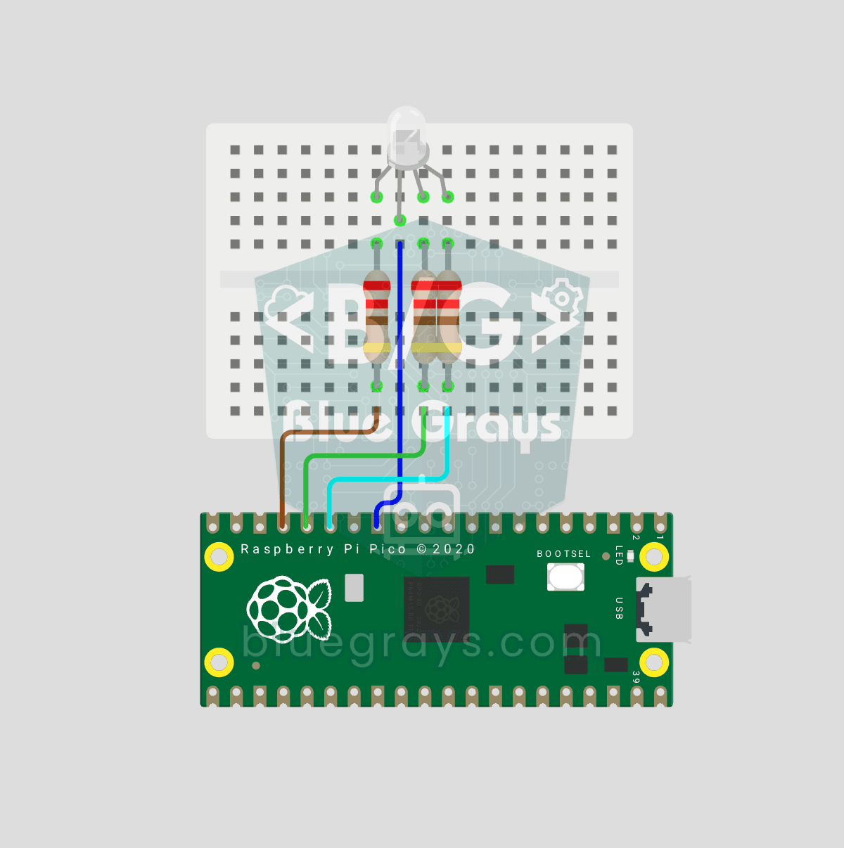
Raspberry Pi Pico RGB LED Color Cycle (3-Channel PWM)
One LED, millions of colors! An RGB LED actually holds 3 separate LEDs: red, green and blue. Set the brightness of each one separately with the Pico's 3 PWM channels and the colors mix: red + green = yellow, green + blue = cyan, all three = white. In this project the LED cycles through 8 colors.

ESP32 LED Fade with PWM
Smoothly changing the brightness of the LED from 0 to max, from max to 0. We control PWM with analogWrite() as in Arduino - the same syntax as ESP32 Arduino Core 3.0+ works without problems. Pin definition + pinMode + analogWrite is enough.

ESP32 LED Brightness Control with a Potentiometer (Analog → PWM)
In this project, we control the brightness of an LED analogically using a potentiometer. The ESP32's ADC pin reads the 0-3.3V voltage from the potentiometer, and this value is then converted into a PWM (Pulse Width Modulation) signal and sent to the LED. As a result, as you turn the potentiometer, the LED gradually brightens and dims. With Arduino Core 3.0+, analogWrite() can be used directly; on the ESP32-S2/S3, the ADC resolution is fixed at 12-bit.
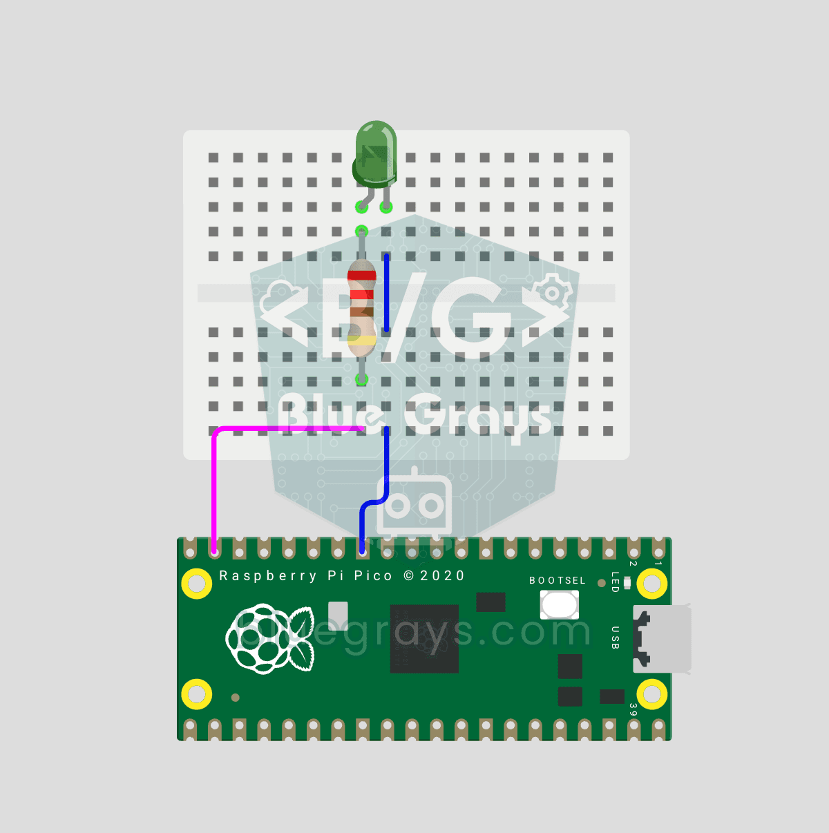
Raspberry Pi Pico PWM LED Fade (Breathing Effect)
The LED doesn't just blink anymore, it breathes! With the Raspberry Pi Pico's PWM (Pulse Width Modulation), the LED's brightness slowly rises and then slowly fades, a calm "breathing" effect like a sleeping laptop's light. You'll learn the machine.PWM class, the 16-bit brightness value from 0–65535 with duty_u16() and the PWM frequency.