
How to Read a Circuit Diagram: Symbols, Junctions, Breadboards
How to read a circuit diagram: resistor, diode, transistor, VCC and GND symbols, junctions vs crossings, net labels, module schematics and breadboard wiring.
How do you read a circuit diagram? The short answer: a schematic is a map that uses standard symbols to show which pin is electrically connected to which, not what the parts look like. To read one, you first recognise the symbols, then follow each line as a connection, tell junction dots apart from simple crossings, read labels and values such as R1 or 220, and finally work out which part of the circuit the VCC and GND symbols supply. These five skills are enough to understand any drawing, from a single LED circuit to the Arduino's own schematic.
In this guide we gather the symbols you'll meet most often in one table and explain how to read the direction of diode and transistor symbols, the difference between crossing and connected wires, the hidden connections made by net names, and what to look for in the schematics of ready-made modules. Then we turn the schematic of a real button, LED and buzzer circuit into a connection list (netlist), transfer it to a breadboard step by step, and give you code to test the finished circuit on an Arduino, ESP32 and Raspberry Pi Pico. In the last sections you'll find the difference between Fritzing's breadboard view and a real schematic, plus the most common reading mistakes.
What is a circuit diagram and what is it for?
A circuit diagram (schematic) is a drawing that shows the electrical structure of an electronic circuit. Components are drawn as symbols, not at their real size or position, and the lines between them don't show the actual path of a wire; they only say that both ends are at the same electrical point. That's why two resistors drawn side by side on a schematic can be far apart on the board, and a long line on the schematic can be a single column of holes on a breadboard. This is where a schematic's power lies: at a glance it shows how the circuit works, which path the current takes, and where to look when something fails.
Well-drawn schematics follow a few common habits: the signal usually flows from left to right (inputs on the left, outputs on the right), higher voltages sit at the top and GND at the bottom. Next to each component is a label (R1, C2, Q1) and a value (220, 100n, BC547). ICs and modules are drawn as rectangles with their pin numbers and names. The table below sums up the building blocks you'll see on a schematic:
| Schematic element | What it looks like | What it tells you |
|---|---|---|
| Symbol | A drawing specific to the component (rectangle, triangle, parallel lines) | The type of component and the direction of its pins |
| Wire (line) | A straight line | Its ends are at the same electrical point; it is not the real wire path |
| Junction | A solid dot | Where three or more lines meet |
| Label (reference designator) | R1, C2, D1, Q1, U1 | Component type and sequence number; the same text is printed on the board |
| Value | 220, 4k7, 100n, BC547 | Resistance, capacitance or part model |
| Net name | A name written on a wire: SDA, LED, BTN | All wires carrying the same name are connected to each other |
| Power symbol | VCC, +5V, 3V3, GND | Supply and ground; symbols with the same name are connected even without a line |
| Pin number | A small number next to a pin | Which physical pin of the IC or connector it is |
The most common circuit diagram symbols
There are two main traditions for drawing symbols: IEC 60617, common in Europe and much of the world, and the American ANSI/IEEE 315. The best-known difference is the resistor: in IEC schematics it's an empty rectangle, in ANSI schematics a zigzag line. Both mean the same component, and since you'll see both in Arduino schematics online, you need to recognise both. The table below covers almost every symbol you'll come across in your first projects:
| Component | Letter code | Schematic symbol | What to watch when reading |
|---|---|---|---|
| Resistor | R | Rectangle (IEC) or zigzag line (ANSI) | No polarity; the value is in ohms (220, 4k7) |
| Potentiometer / trimmer | RV, VR or P | Resistor symbol with an arrow touching its middle | The arrow is the middle pin (wiper); the outer pins are the fixed ends |
| Capacitor (non-polarised) | C | Two equal parallel lines | Ceramic and film capacitors; no polarity |
| Electrolytic capacitor | C | Two plates, one straight and one curved or filled, with a + sign | The + plate goes to positive; reversed, it heats up and bulges |
| Diode | D | A triangle with a bar at its tip | The bar is the cathode; it matches the ring on the body |
| LED | LED or D | Diode symbol with two arrows pointing outwards | The triangle points from the anode (long leg) to the cathode |
| Zener diode | D or ZD | Diode symbol with bent ends on the cathode bar | Connected in reverse; conducts at a specific voltage |
| NPN transistor | Q | Base line inside a circle, arrow on the emitter pointing out | The arrow marks the emitter; the emitter usually goes to GND |
| PNP transistor | Q | Same symbol, arrow pointing in | The emitter usually goes to the positive supply |
| N-channel MOSFET | Q | Gate (G) line separate from the channel, arrow on the body pointing in | G, D and S pins; the arrow direction tells you the channel type |
| Push button (momentary switch) | SW or S | A raised bridge above two contact points | Connects its two ends while pressed |
| Switch (on-off) | SW or S | A slanted line hinged open at one end | Stays where you leave it; an SPDT type has three terminals |
| Battery / DC source | BT or B | Long and short parallel lines | The long line is the positive (+) terminal |
| Relay | K | A coil box with a contact linked to it by a dashed line | The coil and contacts may be drawn in different places on the schematic |
| Buzzer | BZ | Half-circle or bell-shaped symbol with a + terminal | An active buzzer has polarity |
| IC / module | U or IC | A rectangle with numbered pins | The pin number is the physical pin, the text is its function |
Reading direction in diode, LED and transistor symbols
Think of the triangle in a diode or LED symbol as an arrow: current flows in the direction the triangle points, from the anode to the cathode. The bar at the tip of the triangle is the cathode and corresponds to the ring on the body of a real diode. On an LED, the two small arrows pointing away from the triangle represent light; if the arrows point inwards, it isn't an LED but a light-sensing part such as a photodiode or phototransistor. If the LED is the right way round but glows very dimly or soon fails, check the series resistor with the LED resistor calculator.
In a transistor symbol the arrow is always on the emitter and shows the direction of conventional current. On an NPN the arrow points out: current flows from collector to emitter, and the emitter usually goes to GND. On a PNP the arrow points in and the emitter connects to the positive supply. The slanted lead without an arrow is the collector, and the lead meeting the short thick line at a right angle is the base. Here's an important trap: the letters B, C and E on the schematic don't tell you the pin order of the real package. With the flat face towards you, the BC547's legs are C, B, E from left to right, while the 2N2222A and S8050 are E, B, C. So when moving from schematic to breadboard, check every transistor's pinout in the datasheet or with the Transistor tool; for more detail, see What Is a Transistor?.
VCC, GND and power symbols
Drawing the supply lines to every component separately would clutter a schematic, so power symbols are used instead. VCC, +5V or 3V3 written next to an upward arrow or a short horizontal bar marks a supply point, while three horizontal lines getting shorter downwards (a downward triangle in some drawings) marks GND, the ground and reference point. Don't forget the rule: all power symbols with the same name are connected, even with no line between them. A GND at the bottom right of the schematic is the same point as the GND at the top left. That's why all GNDs must be joined, even for modules with separate supplies; What is GND? explains why in detail.
The supply names come from transistor terminals: VCC from the collector supply of bipolar transistors, VDD and VSS from the drain and source of the MOSFETs in CMOS circuits. In practice VCC and VDD mean the positive supply, while VSS and VEE mean GND or a negative supply. If you see AGND (analogue ground) and DGND (digital ground), these are grounds drawn separately to keep noise apart, but they are usually joined at a single point in the end. What voltage to give a module's VCC pin isn't told by the label but by the module's schematic or datasheet.
| Schematic label | Meaning | Arduino Uno | ESP32 DevKit | Raspberry Pi Pico |
|---|---|---|---|---|
| VCC, +5V | 5 V supply | 5V pin | VIN / 5V pin (from USB) | VBUS (pin 40, from USB) |
| 3V3, +3.3V, VDD | 3.3 V supply | 3.3V pin (50 mA max) | 3V3 pin | 3V3(OUT) (pin 36) |
| VIN, VSYS, VBAT | Input before the regulator | VIN (7–12 V recommended) | VIN | VSYS (pin 39, 1.8–5.5 V) |
| GND, VSS, 0V | Ground, common reference | GND pins | GND pins | GND (pins 3, 8, 13, 18, 23, 28, 33, 38) |
| Logic level | HIGH voltage of the pins | 5 V | 3.3 V (not 5 V tolerant) | 3.3 V (not 5 V tolerant) |
Crossing wires and connected wires: the dot rule
What confuses beginners most when reading a schematic is the places where two lines overlap. The rule is simple but strict: if there's a solid dot at the junction, the lines are connected; if there's no dot, they just cross. Older schematics drew unconnected crossings as one line hopping over the other with a small semicircle, and you'll still see this in some textbooks. Modern drawing programs such as KiCad and EasyEDA place the dot automatically when the end of one line touches the middle of another.
- T junction with a dot: three lines meet at one point; they're all on the same net. This is the safest and most common way to draw it.
- Plus-shaped crossing, no dot: two lines pass over each other without touching; there's no connection between them.
- Plus-shaped crossing with a dot: all four lines are connected, but because the dot can get lost in a photocopy or on a small screen, good designers draw it as two offset T junctions.
- Semicircle hop: old style; one line jumps over the other, no connection.
- X at the end of a line: an unconnected pin (NC, no connect); leaving that pin free is a deliberate choice.
Labels, values and net names
The reference designator next to each component is made up of a letter code and a sequence number: R1, R2, C1, D1, Q1, U1. The letter tells you the type: R resistor, C capacitor, L inductor, D diode, Q transistor, U IC, K relay, F fuse, SW switch, J or P connector, Y crystal, BZ buzzer, M motor. On ready-made boards the same labels are printed on the silkscreen, so you can find the schematic's C5 on the board. Values are written in shorthand: 4k7 means 4.7 kΩ, 100n 100 nF and 10u 10 µF; the letter takes the place of the decimal point. If you need to read a value from colour bands, use the Resistor colour code tool; the details of each component family are in Basic Electronic Components.
The real trick to reading schematics is net names. A net is the electrical point formed by all the terminals connected to each other. Since it's impossible to draw every connection as a line on large schematics, the designer writes a name at the end of a wire: SDA, SCL, LED, TX and so on. Two wires carrying the same name are connected, even with no line between them. On the official Arduino Uno schematic, for example, the TX and RX lines of the USB-serial chip connect to the main processor this way, by name. One name can be in one corner of the page and its partner in the other; until you've matched them, you haven't really read the schematic.
| Notation | Meaning | Example |
|---|---|---|
| Letter + number | Reference designator | R3 = third resistor, U2 = second IC |
| 4k7, 2R2, 1M | Resistor value; the letter replaces the decimal point | 4.7 kΩ, 2.2 Ω, 1 MΩ |
| 100n, 104, 10u/16V | Capacitor value and voltage rating | 100 nF; 10 µF, 16 V max |
| Name written on a wire | Net label | All SDAs are connected to each other |
| Name with an overline, /RESET, RESET#, nRESET | Active-LOW signal | The function works when the pin is LOW |
| D[0..7], A0–A3 | Bus | Eight lines shown as one thick line |
| X mark | Unconnected pin (NC) | An IC pin left free |
| Dashed box | Functional block or the outline of a ready-made module | "Power supply", "Sensor module" |
How to read a circuit diagram step by step
- Find the power sources: mark the battery, USB, VIN or adapter input and every VCC, 3V3 and GND symbol. Know from the start what voltage the circuit runs on.
- Identify the main part: an Arduino, ESP32, Pico or IC is usually the big box in the middle of the schematic; everything else is built around it.
- Make a parts list: write down all labels and values (R1 220 Ω, C1 100 nF, Q1 BC547). This list becomes both your shopping list and your checklist.
- Split the circuit into blocks: draw frames around the power, input (button, sensor), processing (board) and output (LED, buzzer, motor) sections.
- Follow each net separately: start at a pin, trace the line to the dots and write down every pin on that net. Don't forget net labels with the same name.
- Mark the polarised parts: highlight the diode's cathode, the LED's anode, the electrolytic capacitor's plus and the transistor's emitter on the schematic.
- Describe the signal path in one sentence: if you can say "pressing the button pulls D2 LOW, the code sets D8 HIGH, Q1 turns on and the buzzer sounds", you've really read the schematic.
Example: reading the schematic of a button, LED and buzzer circuit
Now let's apply what you've learned to a real schematic. Our circuit has seven components. The LED net leaving the Arduino's D9 pin goes through resistor R1 (220 Ω) to the anode of LED1; the LED's cathode is connected to GND. The BTN net on pin D2 goes down to GND through push button SW1 and capacitor C1 (100 nF) in parallel with it. The BZ net leaving pin D8 reaches the base of transistor Q1 (BC547) through R2 (1 kΩ); Q1's emitter is on GND and its collector on the negative terminal of active buzzer BZ1, whose positive terminal is on +5V. The most reliable way to read a schematic is to turn it into a connection list (netlist) like the one below: each row is a net, and all the terminals in that row must meet at a single point on the breadboard.
| Net name | Connected terminals | On the breadboard |
|---|---|---|
| +5V | Arduino 5V, BZ1 (+) | Red (+) power rail |
| GND | Arduino GND, LED1 cathode, one end of SW1, one end of C1, Q1 emitter | Blue (−) power rail |
| LED | D9, one end of R1 | Jumper wire from D9 to R1's column |
| N1 | Other end of R1, LED1 anode | R1 and LED1's long leg in the same five-hole column |
| BTN | D2, other end of SW1, other end of C1 | Button leg and C1 in the same column, jumper from there to D2 |
| BZ | D8, one end of R2 | Jumper wire from D8 to R2's column |
| N2 | Other end of R2, Q1 base | R2 and the BC547's middle leg (B) in the same column |
| N3 | Q1 collector, BZ1 (−) | The BC547's C leg and the buzzer's negative leg in the same column |
Notice two details in the table. First, there's no pull-up resistor on the button in the schematic, because the code will use INPUT_PULLUP and the resistor inside the processor (about 20–50 kΩ on the Uno) will do the job. Good schematics note this with a small comment next to the pin. Second, C1 is a hardware debounce capacitor that smooths out the button's contact bounce; together with the internal pull-up it forms an RC time constant of roughly 2–5 ms. We gave the unnamed nets the names N1, N2 and N3 ourselves; programs like KiCad name them automatically. For more on wiring buttons, see How to Connect a Button to Arduino.
Transferring a schematic to a breadboard
- Print the schematic or keep it on screen beside you and have a highlighter ready; colour in every connection on the schematic as you build it.
- Prepare the power rails: connect the board's 5V to the red (+) rail and its GND to the blue (−) rail. On long breadboards, check whether the rails are split in the middle.
- Place the large parts: seat ICs across the central channel, and plug in modules and the transistor so their legs land in separate columns.
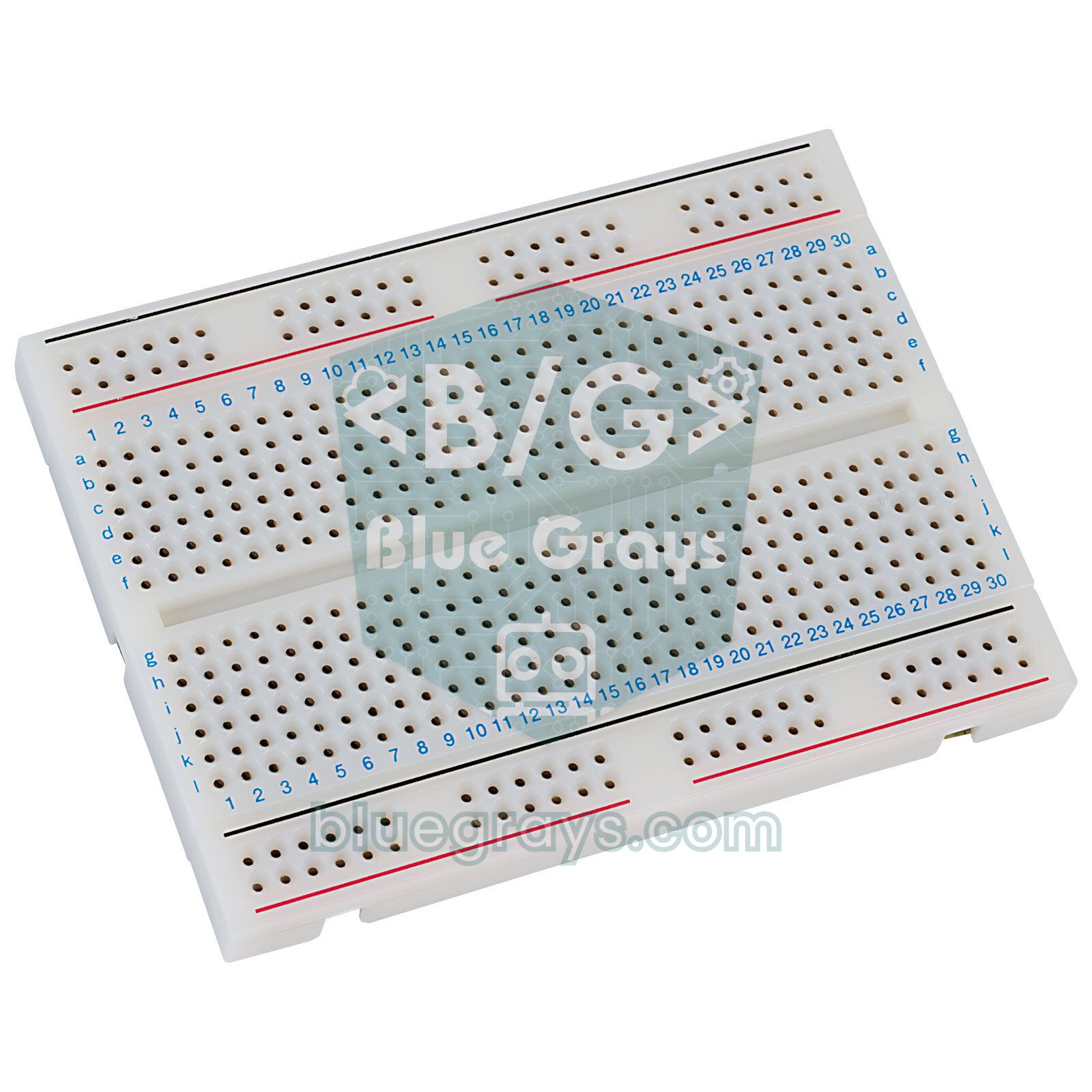
- Assign each net to a column: the five vertical holes on a breadboard are already connected; put the legs on the same net in the same column or join columns with a jumper wire.
- Fit polarised parts by comparing them with the schematic markings: the LED's long leg to N1, and the BC547 with its flat face towards you so the C, B, E order lands in the right columns.
- Give wire colours a rule: red for supply, black or blue for GND, other colours for signals. Colour changes nothing electrically, but it speeds up debugging.
- Measure before powering up: set the multimeter to continuity (beep) mode; first make sure there's no short between 5V and GND, then confirm a beep between the terminals of every row in the netlist.
Testing the circuit you built: Arduino and ESP32 code
The fastest way to know you've transferred the schematic correctly is a small test program that checks each net one by one. The code below first lights the LED for one second at start-up, then sounds the buzzer briefly and prints the current step to the Serial Monitor; after that it watches the button. We kept the constant names in the code the same as the net names on the schematic, so the BZ net on the schematic is BZ_PIN in the code. The same code switches pin numbers by itself on an ESP32; wire it according to the table below.
| Net on the schematic | Arduino Uno | ESP32 | Raspberry Pi Pico |
|---|---|---|---|
| LED (to LED1 via R1) | D9 | GPIO 18 | GP15 |
| BTN (SW1 and C1, other ends to GND) | D2 | GPIO 4 | GP14 |
| BZ (to Q1 base via R2) | D8 | GPIO 19 | GP16 |
| +5V (BZ1 positive terminal) | 5V | VIN / 5V | VBUS |
| GND | GND | GND | GND |
1// Şemadan kurulan devreyi net net test eder / Tests the circuit built from the schematic, net by net
2// Sabit isimleri şemadaki net isimleriyle aynı / Constant names match the net names on the schematic
3#if defined(ESP32)
4const int LED_PIN = 18;   // LED neti: R1 üzerinden LED1 anoduna / LED net: to LED1 anode via R1
5const int BTN_PIN = 4;    // BTN neti: SW1 ve C1, diğer uçları GND / BTN net: SW1 and C1, other ends to GND
6const int BZ_PIN  = 19;   // BZ neti: R2 üzerinden Q1 beyzine / BZ net: to Q1 base via R2
7#else
8const int LED_PIN = 9;
9const int BTN_PIN = 2;
10const int BZ_PIN  = 8;
11#endif
12
13bool lastPressed = false;
14
15void setup() {
16  Serial.begin(115200);
17  pinMode(LED_PIN, OUTPUT);
18  pinMode(BZ_PIN, OUTPUT);
19  pinMode(BTN_PIN, INPUT_PULLUP);   // dahili pull-up, şemada ayrı direnç yok / internal pull-up, no separate resistor on the schematic
20
21  Serial.println(F("1) LED testi / LED test"));
22  digitalWrite(LED_PIN, HIGH);      // N1 netine akım gider, LED1 yanar / current flows into N1, LED1 lights
23  delay(1000);
24  digitalWrite(LED_PIN, LOW);
25
26  Serial.println(F("2) Buzzer testi / Buzzer test"));
27  digitalWrite(BZ_PIN, HIGH);       // Q1 iletime geçer, N3 GND'ye çekilir / Q1 turns on, N3 is pulled to GND
28  delay(300);
29  digitalWrite(BZ_PIN, LOW);
30
31  Serial.println(F("3) Butona bas / Press the button"));
32}
33
34void loop() {
35  bool pressed = (digitalRead(BTN_PIN) == LOW);   // SW1 basılıyken BTN neti GND olur / BTN net goes to GND while SW1 is pressed
36  digitalWrite(LED_PIN, pressed ? HIGH : LOW);
37  digitalWrite(BZ_PIN, pressed ? HIGH : LOW);
38
39  if (pressed != lastPressed) {                    // yalnızca değişince yaz / print only on change
40    if (pressed) {
41      Serial.println(F("Basildi / Pressed"));
42    } else {
43      Serial.println(F("Birakildi / Released"));
44    }
45    lastPressed = pressed;
46  }
47  delay(10);
48}
Three lines in the program relate directly to the schematic. INPUT_PULLUP turns on the internal pull-up resistor that isn't drawn on the schematic, so the pin reads HIGH when the button isn't pressed and LOW when it is, because SW1 connects the net to GND. digitalWrite(BZ_PIN, HIGH) sends current through R2 into Q1's base: on a 5 V Uno this current is (5 − 0.7) / 1000 ≈ 4.3 mA. Since the BC547 has a current gain of at least 110, that easily switches the roughly 30 mA the buzzer draws; on the ESP32 the pin gives 3.3 V, so the base current drops to 2.6 mA, which is still enough. The LED current on the Uno is (5 − 2) / 220 ≈ 14 mA for a red LED; you can repeat these calculations with the Ohm's law calculator.
The same schematic with a Raspberry Pi Pico and MicroPython
The beauty of a schematic is that it doesn't depend on the board: to build the same netlist on a Pico, you simply write different pin numbers next to the net names. On the Pico, connect the buzzer's positive terminal to the VBUS pin (pin 40), which supplies the USB 5 V. GP16 is only connected to the transistor's base through R2; the 5 V side is on the collector and never touches the Pico's pin directly, so the 3.3 V pins stay safe. Save the code to the Pico as main.py with Thonny:
1# Pico: şemadan kurulan devreyi net net test eder / tests the circuit built from the schematic, net by net
2from machine import Pin
3import time
4
5led = Pin(15, Pin.OUT)               # LED neti: GP15 -> R1 -> LED1 / LED net
6btn = Pin(14, Pin.IN, Pin.PULL_UP)   # BTN neti: GP14 -> SW1 + C1 -> GND / BTN net
7bz = Pin(16, Pin.OUT)                # BZ neti: GP16 -> R2 -> Q1 beyz / BZ net to Q1 base
8
9print("1) LED testi / LED test")
10led.on()
11time.sleep(1)
12led.off()
13
14print("2) Buzzer testi / Buzzer test")
15bz.on()                              # Q1 iletime geçer / Q1 turns on
16time.sleep(0.3)
17bz.off()
18
19print("3) Butona bas / Press the button")
20last = False
21while True:
22    pressed = btn.value() == 0       # basılıyken 0 okunur / reads 0 while pressed
23    led.value(pressed)
24    bz.value(pressed)
25    if pressed != last:              # yalnızca değişince yaz / print only on change
26        print("Basildi / Pressed" if pressed else "Birakildi / Released")
27        last = pressed
28    time.sleep_ms(10)
Reading module schematics
Ready-made modules (relay boards, I2C LCD adapters, OLED displays, sensor boards) are really small circuits too, and most of their schematics can be found on the seller's page or in the manufacturer's datasheet. When reading a module schematic, your goal isn't to understand every resistor but to find the five pieces of information that tell you how to connect the module: supply voltage and regulator, logic level, pull-up resistors, active-LOW inputs, and jumpers that select an address or mode. The Arduino Uno's own schematic is good practice too: only the schematic tells you that on the Uno R3 the L LED isn't connected directly to D13 but through an op-amp buffer, the LMV358.
| Module | What to look for on the schematic | What it tells you |
|---|---|---|
| Relay module | Transistor or optocoupler, 1N4148 or 1N4007 diode, JD-VCC jumper | Whether the input is active LOW or HIGH, and whether the coil can be powered separately |
| I2C LCD adapter (PCF8574) | A0, A1, A2 solder jumpers and pull-up resistors | Address: 0x27 on the PCF8574, 0x3F on the PCF8574A; bridging a jumper lowers the address |
| 0.96" OLED (SSD1306) | 3.3 V regulator and SDA, SCL pull-up resistors | That VCC can take 3.3–5 V and no extra pull-ups are needed |
| DHT11 module (3-pin) | A 4.7–10 kΩ resistor on the data line | That you don't need to add a separate pull-up resistor |
| HC-SR04 | 5 V supply and ECHO output | That ECHO outputs 5 V and needs a voltage divider on the ESP32 and Pico |
Fritzing breadboard view vs. schematic: what's the difference?
The colourful drawings you see in most Arduino projects online aren't actually schematics but the breadboard view of a program called Fritzing. Fritzing keeps the same circuit in three views: the breadboard view with photo-like drawings of real parts, the schematic view with standard symbols, and the PCB view for board design. A connection you make in one view appears in the others as dashed ratsnest lines; the program knows the connection exists but leaves it to you to draw it neatly in that view. The schematic view that Tinkercad Circuits draws automatically plays a similar bridging role; details are in Tinkercad Arduino Simulation.
The breadboard view is very comfortable for beginners: it shows exactly which hole each wire goes into. But as the circuit grows, wires cross over each other, it becomes hard to see which row a wire lands in, and you can't tell why the circuit is built that way. A schematic drops physical layout completely and shows only function, which is why you always go back to the schematic to debug, move the circuit to another board or design a PCB. Build a good habit: look at the breadboard drawing while building a project, and at the schematic while trying to understand it.
| Feature | Breadboard view | Schematic | PCB view |
|---|---|---|---|
| What it shows | Realistic drawings of parts and the hole each wire goes into | Symbols and electrical connections | Copper traces, pads and board dimensions |
| Best for | Building for the first time, copying exactly | Understanding, debugging, modifying | Manufacturing a board |
| In large circuits | Wires get tangled and hard to read | Stays tidy with blocks and net names | Gets complex with layers and traces |
| Wire colour and path | Visible but with no electrical meaning | No wire path, only connections | Trace width and length matter |
| Moving to another board | The drawing has to be redone | Only the pin numbers change | The board is redesigned |
Common mistakes and how to fix them
| Mistake | Symptom | Fix |
|---|---|---|
| Taking a crossing without a dot as a connection | Extra wires, sometimes a short circuit | Connect only where there's a solid dot |
| Skipping net labels | I2C or serial communication doesn't work at all | Find and match every label with the same name |
| Not joining the GNDs | The sensor reads nonsense, the module doesn't respond | Bring all GND symbols together at one point |
| Taking the transistor pin order from the schematic | The transistor heats up or the load doesn't work at all | Check the package pinout in the datasheet |
| Fitting a diode or LED backwards | The LED doesn't light, a protection diode shorts the supply | Match the cathode bar with the ring on the body |
| Missing an active-LOW input | The relay clicks on at start-up, the logic works backwards | Watch for pin names with an overline, / or # |
| Mixing up pin numbers and GPIO numbers | The wrong pin responds | On the Pico, physical pin 20 is GP15; use the GP number in code |
| A power rail split in the middle | Half the circuit gets no power | Measure the rail and bridge the two halves with a jumper if needed |
Project ideas to practise reading schematics
- A single LED and resistor: you start with two symbols and three nets; turn the circuit from What Is an LED? into a schematic first, then onto a breadboard.
- Automatic night light: the voltage divider built from an LDR and a 10 kΩ resistor teaches you to read series connections and the shared midpoint on a schematic.
- Traffic light: with three LEDs and three resistors, the Arduino traffic light is ideal for learning to recognise repeated blocks.
- Lamp control with a relay: a relay module schematic brings together a transistor, a diode and an active-LOW input.
- 555 flasher: the 555 timer IC is the classic exercise in reading a box symbol with numbered pins.
- 7-segment counter: 7-segment display schematics show how eight segments are drawn neatly with net names.
Reading circuit diagrams looks like a foreign alphabet at first, but once you've learned the symbols, the dot rule and net names, you'll build every new project by understanding it rather than copying it. As a next step, you can redraw this article's example circuit from scratch in your own drawing program and calculate the currents and voltages on each net with Kirchhoff's laws. In the BlueGrays app you can study the circuit diagrams of projects such as LED blinking, buttons, a night light, a buzzer and a traffic light step by step together with their code, and try what you've learned with real parts straight away.
Frequently asked questions
What do the symbols on a circuit diagram mean?
Each symbol stands for a type of component: a rectangle or zigzag line is a resistor, two parallel lines a capacitor, a triangle with a bar a diode, and a symbol with an arrow inside a circle a transistor. Labels such as R1, C1, D1 and Q1 next to the symbol give the component's type and number, while text like 220 or 100n gives its value. VCC and GND symbols mark the supply and ground points.
What does a dot mean on a circuit diagram?
A solid dot where two or more lines meet shows that those lines are electrically connected. At plus-shaped crossings without a dot, the lines just pass over each other and aren't connected. Older schematics also draw unconnected crossings with a small semicircle hop.
What do VCC and GND mean on a schematic?
VCC is the circuit's positive supply line; it's usually 5 V on an Arduino Uno and 3.3 V on the ESP32 and Pico. GND is ground, the 0 V reference point against which all voltages are measured. All VCC and GND symbols with the same name on a schematic are connected, even with no line between them.
What's the difference between a schematic and a breadboard diagram?
A breadboard diagram shows what the parts really look like and which hole each wire goes into; it's easy to copy but becomes unreadable in large circuits. A schematic shows only the electrical connections with standard symbols and explains how the circuit works. Programs such as Fritzing and Tinkercad can show the same circuit in both views.
Which software is used to draw circuit diagrams?
KiCad, free and professional, is the most widely used program for schematics and PCB design. EasyEDA runs in the browser and links directly to board ordering, while Fritzing, with its breadboard view, suits beginners. In Tinkercad Circuits you can also see the schematic of the circuit you built automatically.
Is a wiring diagram the same as a schematic?
Not quite. A wiring diagram usually shows the physical layout and the actual wires between parts, such as the fuses, sockets, switches and lamps in a building, often as a single-line diagram. An electronic schematic shows the pin-by-pin connections of components like resistors, transistors and ICs without caring where they sit. The dot rule, symbol logic and labels work in a similar way in both.
Projects to build after reading this
See all projects
LED Blink
The very first hello of electronics: switching a single LED on and off. The Arduino turns the LED on and off at short intervals, so the light blinks quickly. You see in the simplest way how the board

LED Control with a Push Button (Push)
Just like a doorbell: the light stays on as long as you press, and goes off when you let go. The Arduino keeps listening to the button; while it's pressed the LED is on, and the moment you lift your f

Traffic Light
A tiny copy of the traffic light you see on the road every day. Red stays on for two seconds, yellow flashes for a moment, green stays on for two seconds, then it goes back to red through yellow again

Night Light with Ldr
A little night light that turns on by itself when it gets dark and goes off when morning comes. A light sensor measures how bright the room is, and the Arduino switches the LED on when it is dark enou
Using a Buzzer
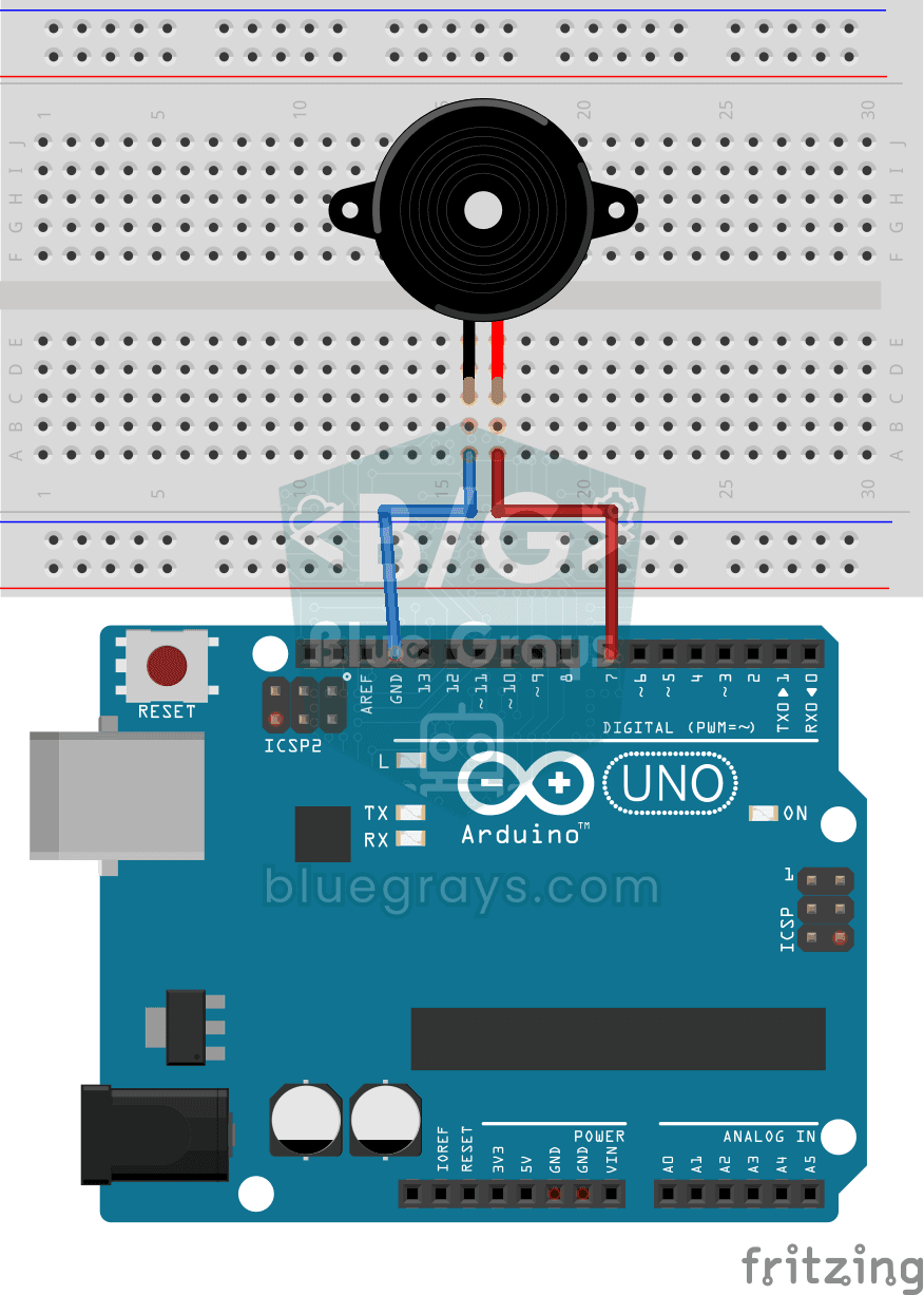
Ever wondered how a doorbell or an alarm makes its sound? The Arduino makes a small buzzer beep at short intervals: beep, pause, beep, pause. You see how sound is made with electricity and take the fi
Raspberry Pi Pico: Controlling an External LED (Breadboard)
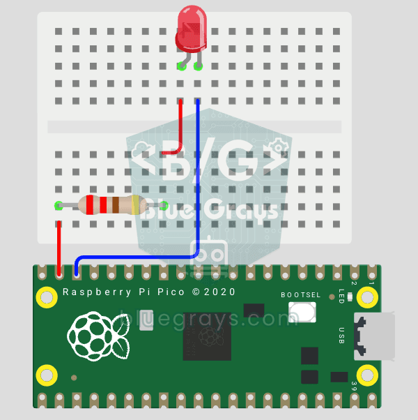
The next step after Pico’s built-in LED: connecting an external LED to the breadboard and controlling it via the GP14 pin. In this project, you’ll learn how to use any of the Pico’s general-purpose GPIO pins as an output, the LED’s polarity (long leg = anode/+, short leg = cathode/–), and why a current-limiting resistor (220Ω) is required. If you don’t include the resistor, excessive current will flow through the LED and it may burn out. The circuit is very simple: Pico GP14 → 220Ω resistor → LE

ESP32 LED Control with Push Button (Push)
The LED lights up when the button is pressed and turns off when released. Shows how the ESP32's digital input pin and internal pull-up resistor are used. The INPUT_PULLUP mode eliminates the need for an external resistor.
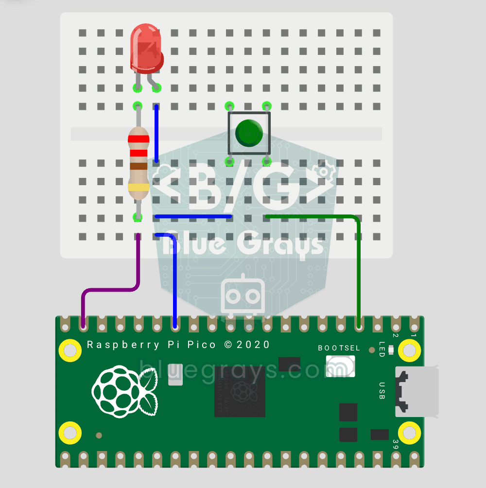
Raspberry Pi Pico Button Controlled LED (Push)
First input project with Pico — button read! LED lights while button is pressed, off when released. This is the big step after LED animations: signal input from the world to Pico. Learn Pin.IN (input mode), Pin.PULL_UP (internal pull-up resistor — standard for buttons), button.value() reading. GP14 LED, GP2 button (internal PULL_UP). Pressed = LOW (0), released = HIGH (1) — reverse logic seems confusing at first but is industry standard.