
How to Solder: Iron Temperature, Solder Wire and Pin Headers
How to solder step by step: iron temperature, leaded vs lead-free solder, tip tinning, pin headers, cold joints, bridges, desoldering and heat shrink splices.
The short answer to how to solder is this: touch a clean, tinned soldering iron tip to the copper pad on the board and to the component lead at the same time, and heat the joint for 1–2 seconds; then feed the solder wire into the heated joint, not onto the iron. Once the solder melts and flows over the pad and the lead, pull the wire away first, then the iron, and don't move the part until the joint has cooled. At the right temperature the whole thing takes 3–4 seconds and leaves a smooth joint shaped like a small volcano around the lead.
If you work with Arduino, ESP32 or the Raspberry Pi Pico, you can't avoid soldering for long: most sensor modules ship with their pin headers loose in a bag, the Pico and the Arduino Pro Mini usually come without pins, and the motor wires of a robot car and the ends of LED strips need soldering too. In this guide you'll learn step by step how to choose a soldering iron and solder wire, set the temperature, clean and tin the tip, and solder pin headers onto modules. Then you'll see how to tell a good joint from a bad one, find and fix cold joints and solder bridges, desolder with a solder sucker and wick, splice wires and insulate them with heat shrink, and follow the safety rules that protect both your health and your board.
What is solder and how does it work?
Solder is a tin-based alloy with a melting point far lower than copper's (roughly 180–230 °C). When molten solder touches a clean copper surface, it wets it: a thin intermetallic layer forms between the tin and the copper, and the two metals bond chemically. So solder isn't glue; it creates both an electrical and a mechanical connection between the component lead and the copper ring on the board (the pad). Two conditions must be met for that bond to form: the surfaces must be heated above the solder's melting point, and the oxide layer on them must be removed. The iron supplies the heat, and the flux (rosin) inside the solder wire dissolves the oxide. When solder won't stick, the problem is almost always one of these two: either the joint isn't hot enough, or the flux has burned off and the surface has oxidized again.
Choosing a soldering iron: power, temperature control and tip
When you buy an iron for electronics, the first thing to look at isn't the wattage but temperature control. Cheap unregulated pencil irons keep heating up as long as they're plugged in and can exceed 400 °C at idle; that blackens the tip quickly, burns off the flux instantly and can lift pads off the board. A temperature-controlled iron holds the tip at the value you set. The wattage tells you how quickly the heater recovers, not how hot it gets: a 60 W regulated iron touching a large GND area brings the temperature back much faster than a 25 W iron. For hobby electronics, the ideal starting point is a soldering station or adjustable pencil iron rated at 50–80 W and adjustable between 200 and 450 °C.
| Iron type | Typical power | Temperature control | For Arduino work |
|---|---|---|---|
| Unregulated pencil iron | 25–40 W | None | Gets by; the tip wears out fast and the risk of lifting pads is high |
| Adjustable pencil iron | 60–80 W | Dial or digital setting | A good start |
| Soldering station | 50–90 W | Digital, with a sensor | The best choice; tips are easy to swap |
| USB-C powered smart iron | 40–90 W (depends on the adapter) | Digital | Portable; needs a strong USB-C PD adapter |
| Soldering gun | 100 W and up | None | Meant for thick wires, not for circuit boards |
| Hot air station | Depends on the heater | Digital | For SMD removal and shrinking heat shrink |
The temperature setting depends on the solder you use. The rule is simple: the tip should be about 120–150 °C above the solder's melting point, because heat is lost on its way from the tip into the joint, and the joint itself has to get comfortably past the melting point. The values below are a good starting point for 2.54 mm pin headers and standard through-hole parts:
| Solder wire | Melting point | Recommended tip temperature |
|---|---|---|
| Sn63/Pb37 (leaded, eutectic) | 183 °C | 300–330 °C |
| Sn60/Pb40 (leaded) | 183–190 °C | 320–350 °C |
| SAC305 (Sn96.5/Ag3/Cu0.5, lead-free) | 217–220 °C | 350–370 °C |
| Sn99.3/Cu0.7 (lead-free) | 227 °C | 360–380 °C |
| Large GND area, thick wire | Same | 20–30 °C more, or a wider tip |
Choosing the tip matters as much as the temperature. Heat passes through the surface where the tip touches the joint; a pointed conical tip touches a pin header lead at just one point and transfers heat slowly. Beginners try to make up for that by raising the temperature and end up burning the board. For through-hole (THT) parts and pin headers, a 1.6–2.4 mm chisel (type D) tip or an angled bevel (type C) tip is ideal. A fine conical tip is only for very cramped SMD work; for thick wires and motor terminals, use a chisel tip of 3 mm or more.
Choosing solder wire: leaded, lead-free and rosin core
Solder wire is a thin alloy wire with one or more cores of flux inside. On the package you'll see a code such as Sn60/Pb40: it means the alloy is 60 percent tin (Sn) and 40 percent lead (Pb). Leaded solders melt at a lower temperature, flow easily and leave a shiny surface, which makes them the most forgiving choice for learning. Sn63/Pb37 in particular is a eutectic alloy, meaning it solidifies all at once at a single temperature (183 °C); because it doesn't pass through a pasty stage while cooling, the risk of a cold joint is lower even if the part moves slightly. Lead-free solders (tin-silver-copper alloys such as SAC305) are used in commercial electronics because of the RoHS directive; they need a higher temperature, flow a little less readily and naturally look dull.
| Property | Leaded (Sn63/Pb37, Sn60/Pb40) | Lead-free (SAC305) |
|---|---|---|
| Melting point | 183–190 °C | 217–220 °C |
| Flow and wetting | Very good, forgiving | Slower, needs more flux |
| What a good joint looks like | Shiny, smooth | Dull or satin, slightly grainy |
| Tip life | Long | Shorter because of the higher temperature and tin content |
| Health | Contains lead, washing your hands is a must | No lead, but flux fumes are still harmful |
| Where it's used | Hobby, repair, learning | Commercial products, work that requires RoHS |
As for diameter, 0.6–0.8 mm is ideal for through-hole parts such as 2.54 mm pin headers, resistors and LEDs; 1 mm wire suits thick cables and motor terminals, while 0.3–0.5 mm keeps you from using too much solder on SMD work. The flux inside the wire is usually 1–3 percent by weight, and the package will say rosin, RMA or no-clean. Rosin flux is the classic type; no-clean flux leaves little residue and in most hobby work can be left as is. For jobs like desoldering and fixing bridges, it's well worth getting a flux pen or a rosin-based flux paste made for electronics. You can clean the sticky brown flux residue left at the end with isopropyl alcohol (99 percent IPA) and an old toothbrush.
Tools and materials you need for soldering
- Adjustable soldering iron and stand: A stand is a must so you never lay a hot iron on the desk.
- Solder wire: 0.8 mm, rosin core; Sn60/Pb40 or Sn63/Pb37 to start with.
- Tip cleaner: Brass wool (recommended) or a slightly damp cellulose sponge.
- Flux pen or rosin paste: For fixing bridges, desoldering and oxidized surfaces.
- Desoldering wick and solder sucker: For undoing a bad joint.
- Flush cutters and wire stripper: For trimming leads and stripping insulation cleanly.
- Heat shrink tubing: A small 2:1 set in several diameters.
- Helping hands or a PCB holder: To hold the board and wires steady; models with a magnifier help with fine work.
- Safety glasses and a fume extractor fan: They protect your eyes from spattering solder and your lungs from flux fumes.
- Multimeter: For checking shorts and open connections after soldering.
Cleaning and tinning the soldering iron tip
A soldering tip is a copper core plated with iron on the outside. As long as that plating stays wetted with solder, it transfers heat to the joint very well. As the tip is exposed to air, especially when it sits idle at a high temperature, it oxidizes, turns black and no longer takes solder: instead of sticking to the tip, the solder beads up and rolls off. This is what people call a dead tip. The secret to keeping the tip alive is to always keep it coated with a thin layer of solder; this is called tinning.
- First use: As a new tip warms up and reaches about 200 °C, touch solder wire to it and tin it all over. That way it won't oxidize in the very first minute.
- Every few joints: Poke the tip into brass wool or wipe it quickly on a damp sponge. The sponge should be wrung out and slightly damp, not soaking; use distilled or filtered water.
- Tin right after wiping: Put a small amount of fresh solder on the clean, shiny tip. A clean but bare tip oxidizes again within seconds.
- During breaks: Leave a small blob of solder on the tip before putting the iron in its stand; if you'll be away for more than a few minutes, lower the temperature to around 200 °C or switch the iron off.
- Before switching off: Don't wipe the tip; coat it with a thick layer of solder and then switch off. That layer protects the tip from air while it cools.
- If the tip has turned black: Dip the hot tip into tip tinner a few times and clean it in brass wool. Never sand, file or scrape the tip with a knife; once the iron plating is gone, the tip dies completely in no time.
How to solder, step by step
The steps below are for soldering a through-hole (THT) part such as a resistor, an LED or a pin header to a board. If you do your first attempts on an old board or with a few resistors on perfboard, your hands will get used to it quickly.
- Preparation: Set the iron to the right temperature for your solder, then clean and tin the tip. If the board or the component leads are greasy or oxidized, wipe them with alcohol.
- Place the part: Push the leads through the holes and bend them slightly outward, about 30°, so the part doesn't fall out when you flip the board.
- Heat: Rest the tip at about a 45° angle so that it touches the lead and the copper pad at the same time, and hold it there for 1–2 seconds.
- Feed the solder: Touch the solder wire to the point where the lead meets the pad, from the side opposite the iron. The heated joint should melt the wire; don't touch the wire to the iron tip and let it drip.
- Get the amount right: Stop when the solder has spread over the whole pad and formed a small cone around the lead. For a 2.54 mm pin header, 2–4 mm of wire is usually enough.
- Remove the wire first, then the iron: After pulling the wire back, keep the iron there for another half second, then lift it away upward along the lead.
- Don't move it: The solder sets in 2–3 seconds; don't move the board or the part during that time, and there's no need to blow on it.
- Trim the lead and check: Cut the excess lead with flush cutters just above the solder, leaving about 1 mm; hold the end with your finger so it doesn't fly off. Finally, inspect the joint under good light.
At the right temperature the whole process shouldn't take more than 3–5 seconds. If the solder doesn't flow within 5 seconds, don't keep heating the joint; lift the iron, let the joint cool, add a little flux, clean the tip and try again. There's a small trick to get heat into the joint faster: the moment you touch the iron to the joint, dab a tiny bit of solder at the contact point. That little bit of molten solder works as a heat bridge and enlarges the contact area. Carrying solder on the iron tip and smearing it onto the joint, however, is wrong: the flux in solder sitting on the tip burns off within seconds, and what reaches the joint is oxidized solder that won't flow.
Soldering pin headers and modules
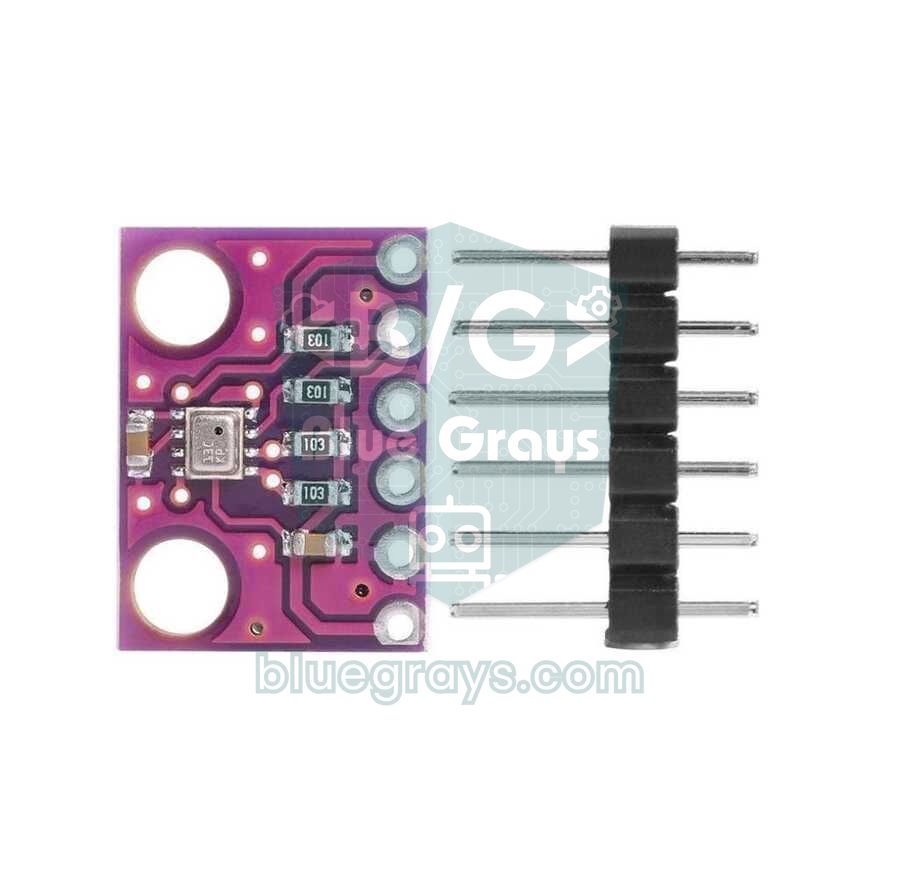
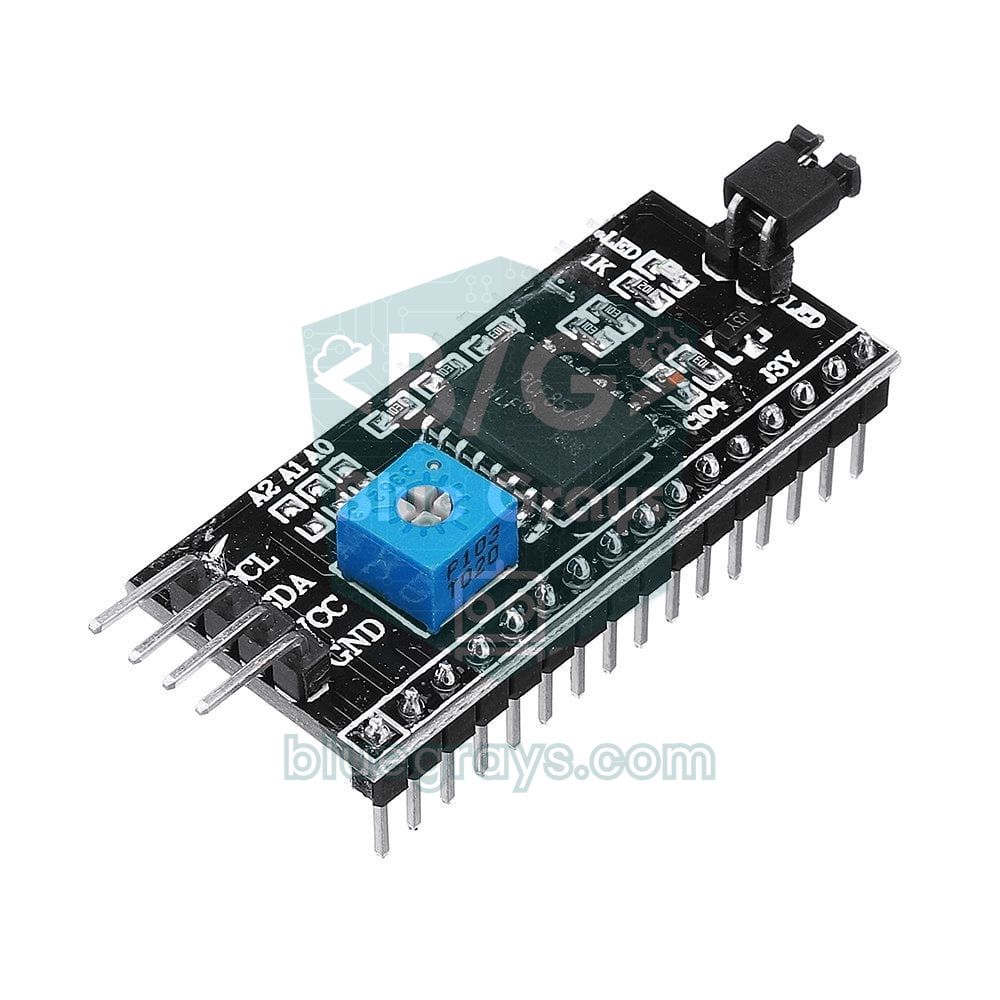
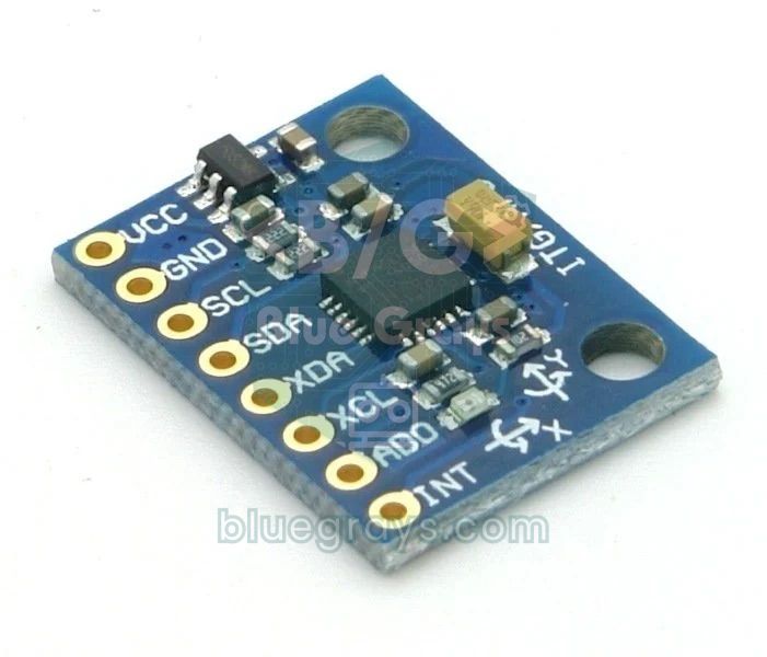
The soldering you'll do most often in Arduino projects is fitting a pin header (a strip of 2.54 mm pitch male pins) to a sensor or module. Modules such as the MPU-6050, BME280 and HX711, I2C LCD adapters, the Raspberry Pi Pico and the Arduino Pro Mini often arrive with their pins unsoldered. The real challenge here isn't the soldering itself but keeping the pins perfectly straight and square to the board. The easiest way to do that is to use a breadboard as a jig.
- Break off as many pins from the header strip as you need, using flush cutters or pliers; cut one pin further along so the plastic of the end pin isn't damaged.
- Push the long legs of the header into the breadboard, spaced to match the module's pin rows. For boards with two rows (Pico, Pro Mini), insert both strips at the same time.
- Set the module onto the short legs with the side carrying the chips and components facing up.
- Solder only one corner pin first, then look from the side to check that the module sits flat.
- If it's crooked, reheat that pin and straighten the module by pressing gently with a pen or tweezers, not with your finger.
- Once you're sure it's level, solder the pin in the opposite corner; now the module is held at two points.
- Solder the remaining pins one by one. Don't spend more than 2–3 seconds on each pin so the breadboard plastic doesn't heat up; on boards with many pins, alternate between the two sides to let the heat spread.
- When you're done, take the module out of the breadboard, inspect all the pins closely with a magnifier or your phone camera, and check that there are no bridges between neighboring pins.
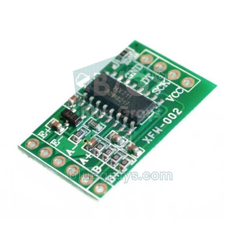
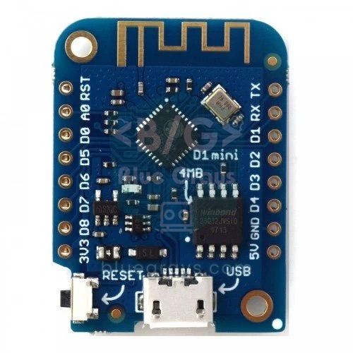
On the Raspberry Pi Pico you solder 40 pins in two rows of 20; this can take 10–15 minutes on your first try, so don't rush. On the Pico, the GP numbers are printed on the underside of the board, and once the headers are fitted from below, those labels are hidden; so keep a pinout diagram next to you. Because its edges are castellated (half holes), the Pico can also be soldered directly onto another board without headers. For what each pin does, see What Is the Raspberry Pi Pico?. When soldering an I2C LCD adapter onto a display, make sure the pin 1 markings match; the details are in Using an I2C LCD Display. If you're not sure which pin goes where, you can open your board's pin map in the Pinout tool.
What does a good solder joint look like versus a bad one?
A good solder joint looks like a small cone, or volcano, that covers the whole pad and rises toward the lead in a concave curve. Its edges blend into the pad and the lead at a shallow angle, which shows the solder has wetted both surfaces. With leaded solder the surface is shiny and smooth. With lead-free solder, even a good joint looks dull or satin, so with lead-free solder judge the shape rather than the shine. In plated through-holes, if the solder fills the hole and forms a thin ring on the other side of the board as well, the heat has made it all the way through the hole.
| Appearance | What it means | Fix |
|---|---|---|
| Smooth, concave cone; pad fully covered | Good joint | Leave it alone |
| Bulging like a ball or droplet, edges don't blend into the pad | Too much solder, or the pad wasn't heated and didn't wet | Add flux, reheat and remove the excess with wick |
| Gray, dull, rough, cracked or wrinkled surface | Cold joint, or a joint that moved while cooling | Add flux and reheat until the joint flows completely |
| Pad partly exposed, hole not filled | Not enough solder | Reheat and add a little more solder |
| Solder joined to the neighboring pin | Solder bridge, short circuit | Separate it with flux and a clean tip, or remove it with wick |
| Dark ring around the lead, solder hasn't taken to the lead | Lead oxidized or not heated | Clean the lead, add flux, and resolder while heating the lead too |
| Pointed tip (like an icicle) | Flux ran out, or the iron was pulled away too slowly | Add a little flux and remelt with a brief touch |
| Brown burnt flux, lifted or torn pad | Excessive temperature or heating for too long | Lower the temperature; bridge a torn pad to its trace with a thin wire |
Cold solder joints and solder bridges
A cold solder joint is when the solder has melted and sits on the joint but hasn't formed a real bond with the copper. It has three typical causes: the joint wasn't heated enough (usually only the lead or only the pad was heated), the surface was oxidized and there wasn't enough flux, or the part moved while the solder was setting. A cold joint is a sneaky fault, because the circuit sometimes works and sometimes doesn't. A sensor that works again when you press on the module, an I2C device that keeps dropping out, or a robot that resets when it vibrates are usually signs of a cold joint. The fix is easy: add a little flux to the joint, heat it with a clean tip until the solder flows completely and turns shiny, and add a tiny bit of fresh solder if needed.
A solder bridge is when excess solder creates a path between two neighboring pins. It forms easily even on 2.54 mm headers and can connect two signals together or, worse, 5V and GND. To fix a bridge, first apply flux, then drag a clean, tinned tip from the middle of the bridge outward away from the pins; thanks to the flux, the solder splits between the two pins. If there's still too much solder, remove it with wick. The most reliable way to find bridges you can't see is to check neighboring pins with your multimeter's continuity (beep) setting; how to do that is explained in How to Use a Multimeter.
After the multimeter check, you can use the board itself as a test tool. The sketch below holds the signal pins of an Arduino Uno, Nano or Pro Mini HIGH with the internal pull-up resistors. Plug the board with its freshly soldered headers into a breadboard, connect a jumper wire to a GND pin, and touch the free end of the wire to each pin in turn. In the Serial Monitor (9600 baud), each touch should show only the name of the pin you touched.
1// Lehim testi: header pinlerine GND kablosuyla tek tek dokun / Solder test: touch each header pin with a GND wire
2// Önce multimetreyle 5V ile GND arasında kısa devre olmadığını ölç / First make sure 5V and GND are not shorted (multimeter)
3// 0-1 seri port, 13 dahili LED yüzünden listede yok / 0-1 (serial) and 13 (onboard LED) are left out
4const uint8_t PINS[] = {2, 3, 4, 5, 6, 7, 8, 9, 10, 11, 12, A0, A1, A2, A3, A4, A5};
5const uint8_t PIN_COUNT = sizeof(PINS) / sizeof(PINS[0]);
6bool wasLow[PIN_COUNT];
7
8void printPin(uint8_t pin) {
9  if (pin >= A0) {                       // analog pinleri A0..A5 diye yaz / print analog pins as A0..A5
10    Serial.print('A');
11    Serial.print(pin - A0);
12  } else {
13    Serial.print('D');
14    Serial.print(pin);
15  }
16}
17
18void setup() {
19  Serial.begin(9600);
20  for (uint8_t i = 0; i < PIN_COUNT; i++) {
21    pinMode(PINS[i], INPUT_PULLUP);      // boştayken HIGH okunur / reads HIGH while idle
22  }
23  delay(50);
24  Serial.println(F("Lehim testi basladi / Solder test started"));
25  for (uint8_t i = 0; i < PIN_COUNT; i++) {
26    wasLow[i] = (digitalRead(PINS[i]) == LOW);
27    if (wasLow[i]) {                     // dokunmadan LOW: GND'ye köprü / LOW untouched: bridged to GND
28      Serial.print(F("GND'ye kisa devre? / Short to GND? "));
29      printPin(PINS[i]);
30      Serial.println();
31    }
32  }
33}
34
35void loop() {
36  bool changed = false;
37  uint8_t lowCount = 0;
38  for (uint8_t i = 0; i < PIN_COUNT; i++) {
39    bool low = (digitalRead(PINS[i]) == LOW);
40    if (low != wasLow[i]) {
41      wasLow[i] = low;
42      changed = true;
43    }
44    if (low) lowCount++;
45  }
46  if (changed && lowCount > 0) {         // yalnız değişince yaz / print only on change
47    Serial.print(F("LOW:"));
48    for (uint8_t i = 0; i < PIN_COUNT; i++) {
49      if (wasLow[i]) {
50        Serial.print(' ');
51        printPin(PINS[i]);
52      }
53    }
54    if (lowCount > 1) {
55      Serial.print(F("  <- kopru olabilir / possible bridge"));
56    }
57    Serial.println();
58  }
59  delay(20);                             // dokunma titreşimini süz / filter contact bounce
60}| What you see in the Serial Monitor | What it means |
|---|---|
| The pin you touched appears on its own | The joint is good |
| You touch a pin but nothing is printed | Open connection or cold joint; the pin isn't connected to the board |
| Touching one pin prints two pins at once | There's a solder bridge between those two pins |
| A short-to-GND warning at startup | That pin is bridged to GND |
Pins 0 and 1 are left out of the list because they're used by the serial port, and pin 13 because its onboard LED can upset the pull-up reading. A6 and A7 on the Nano and Pro Mini are analog inputs only and can't be read digitally; check those with a multimeter. Touching the pins with a GND wire is safe, because the 20–50 kΩ internal pull-up resistor keeps the current below 0.25 mA. If you've soldered headers onto a Raspberry Pi Pico, you can run the same test in MicroPython from Thonny:
1from machine import Pin
2import time
3
4# Pico kenar pinleri: GP0-GP22 ve GP26-GP28 / Pico header GPIOs: GP0-GP22 and GP26-GP28
5numbers = list(range(23)) + [26, 27, 28]
6pins = [Pin(n, Pin.IN, Pin.PULL_UP) for n in numbers]   # boşta 1 okunur / reads 1 while idle
7time.sleep_ms(50)
8
9was_low = [p.value() == 0 for p in pins]
10for n, low in zip(numbers, was_low):
11    if low:                                  # dokunmadan 0: GND'ye köprü / 0 untouched: bridged to GND
12        print("GND'ye kisa devre? / Short to GND? GP%d" % n)
13print("GND kablosunu pinlere tek tek degdir / Touch each pin with the GND wire")
14
15while True:
16    low_now = [p.value() == 0 for p in pins]
17    if low_now != was_low:                   # yalnız değişince yaz / print only on change
18        was_low = low_now
19        touched = ["GP%d" % n for n, low in zip(numbers, low_now) if low]
20        if touched:
21            note = "  <- kopru olabilir / possible bridge" if len(touched) > 1 else ""
22            print("LOW: " + " ".join(touched) + note)
23    time.sleep_ms(20)                        # dokunma titreşimini süz / filter contact bounce
This code checks all 26 GPIO pins along the Pico's edges (GP0–GP22 and GP26–GP28); the GND, 3V3, VSYS, VBUS, 3V3_EN, ADC_VREF and RUN pins aren't in the list, so measure those with a multimeter. The code also runs unchanged on the Pico W. With the GND wire connected to any GND pin on the Pico, touching each GP pin in turn should show only that pin's name in Thonny's Shell window.
Desoldering with a solder sucker and desoldering wick
You'll need to remove solder when a header is fitted to the wrong side, an LED is soldered in backwards, or you want to salvage a part from an old board. There are two basic tools for this: the solder sucker (a vacuum desoldering pump), which clears a hole in one go, and desoldering wick (a fine copper braid soaked in flux), which soaks up molten solder by capillary action. The pump is better for clearing the holes of through-hole parts, and the wick is better for removing excess solder from surfaces, bridges and SMD pads. With both methods, adding a little fresh solder to the old solder first makes the job easier: the fresh flux dissolves the oxide, and with more molten solder the heat travels better. On factory boards made with lead-free solder, adding a bit of leaded solder also lowers the melting point of the mix.
Desoldering with a solder sucker:
- Push the plunger down until it locks.
- Heat the joint with the iron and make sure the solder has melted completely.
- Rest the pump's Teflon nozzle on the molten solder, square to the board, right next to the iron.
- Lift the iron and immediately press the pump's button; the plunger snaps back and sucks up the solder.
- If the hole isn't fully clear, add a little fresh solder and repeat. Open the pump now and then to empty out the solder that collects inside.
Desoldering with wick:
- Put a little flux on the end of the wick; cut off any part that's already used and full of solder.
- Lay the wick on the solder you want to remove.
- Press the iron tip on top of the wick; when the solder melts, the wick soaks it up and turns silver.
- Lift the wick and the iron together. If you pull the wick away after the solder has set, you can tear the pad off too.
- Cut off the part full of solder and repeat with a clean section if needed. When you're done, clean off the flux residue with alcohol.
Splicing wires and using heat shrink
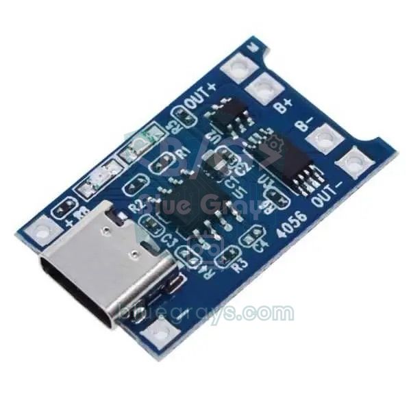
When connecting wires to motors, battery holders, LED strips or charging modules, solder is far more reliable than jumper wires: it doesn't come loose under vibration and the contact resistance is low. First strip 5–7 mm of insulation from the wires and gather the strands of stranded wire by twisting them with your fingers. Then pre-tin each end separately: when you feed solder onto the heated wire, it wicks in between the strands and the end becomes stiff. When you lay two pre-tinned ends against each other, a brief touch of heat is enough to join them.
- Slide the heat shrink on first: Before joining, slide a piece of heat shrink tubing of the right diameter onto one of the wires and keep it 3–4 cm from the joint so the heat doesn't affect it.
- Strip and tin: Strip 5–7 mm from the ends of both wires, twist the strands and pre-tin them.
- Join: Lay the ends side by side or overlap them end to end; for a stronger splice you can wrap the strands around each other.
- Solder: Touch the iron to the joint, let the solder flow between the strands, and add a tiny bit more solder if needed. If solder wicks all the way under the insulation, the wire becomes stiff and breaks at that point, so don't overheat it.
- Let it cool and check: Tug the splice gently to test its strength, and make sure no sharp strands are sticking out.
- Shrink the tubing: Slide the tubing over the splice so it overlaps at least 5 mm on each side, and heat it evenly with a heat gun. A lighter or the soldering iron shrinks it unevenly and can burn it.
Standard heat shrink tubing shrinks at a 2:1 ratio, meaning its diameter halves when heated. So its unshrunk inner diameter should be slightly bigger than the thickest part of the splice, and its shrunk diameter smaller than the wire itself. For splices that will be outdoors or may get wet, use adhesive-lined 3:1 tubing; when heated, the glue inside melts and seals the splice. If you're soldering wires to DC motor terminals, adding a 100 nF ceramic capacitor across the two motor terminals reduces electrical noise; the details are in DC Motor Control with the L298N. Don't tin wire ends that go into screw terminals, though: over time the solder creeps under the pressure of the screw, the connection loosens and the contact point heats up. For those connections, use wire ferrules.
Safety and ventilation
- Don't breathe the fumes: The white smoke you see while soldering isn't lead, it's burning flux. Rosin (colophony) fumes irritate the airways, and long-term exposure can cause occupational asthma. Open a window and use a fan that blows the fumes away from your face, or an activated carbon fume extractor.
- Mind the lead: Lead doesn't evaporate at soldering temperatures; the real risk is getting it from your hands into your mouth. Don't eat while soldering, don't keep drinks on the desk, wash your hands with soap when you finish, and don't leave solder scraps on the desk.
- Wear glasses: Clipped leads can fly off, and tiny droplets of solder can spatter when the flux heats up.
- Use an iron stand: Never lay the iron on the desk or on cables; keep the iron's own cord away from the hot tip too.
- Work without power: Unplug the USB cable and remove the battery from the board you're soldering; in circuits with large capacitors, make sure they're discharged first.
- Cool water for burns: Immediately hold the burn under cool running water for 20 minutes; don't put ice or toothpaste on it.
- Supervise children: Children learning to solder should work next to an adult; the tip is around 350 °C and stays hot for minutes after it's switched off.
- Switch off when you're done: Unplug the iron, leave it in its stand until it cools, and air out the work area.
Project ideas to practice soldering
- Headers on sensor modules: 6–8 pin modules such as the BME280 and BMP280 or the MPU6050 are ideal for your first header.
- Robot car wiring: When you build an Arduino robot car, solder wires to the motor terminals and insulate the splices with heat shrink.
- LED strip connection: Solder the 5V, GND and data wires to the pads of a WS2812B NeoPixel strip.
- Permanent circuit: Make a circuit that works on a breadboard permanent by moving it to perfboard.
- Tiny board: Solder headers onto an Arduino Pro Mini and check every pin with the test sketch above.
- Portable power: Build your own rechargeable power pack with a TP4056 charging module and a battery holder.
- Your own PCB: Once you're comfortable soldering, design a PCB with EasyEDA and turn your circuit into a professional board.
Common mistakes and how to fix them
| Problem | Likely cause | Fix |
|---|---|---|
| Solder balls up on the iron tip and won't stick | Oxidized tip (dead tip) | Clean it in brass wool and tin it with tip tinner |
| Solder won't stick to the pad and rolls around the lead | The pad isn't heated or is oxidized | Touch the tip to the pad as well, add flux, use a wider tip |
| Solder melts but freezes as soon as it touches the joint | Temperature too low or tip too small; a GND area is drawing the heat away | Raise the temperature by 20–30 °C or switch to a chisel tip |
| Flux turns black instantly, lots of smoke | Temperature too high | Lower the temperature to suit the solder type |
| The module works when pressed and cuts out when released | Cold joint | Add flux to the suspect pins and remelt them |
| USB disconnects or the board gets hot when plugged in | A 5V–GND short caused by a solder bridge | Find it with a multimeter and remove the bridge with flux and wick |
| The header is crooked | All pins were soldered without tacking it first | Reheat one pin and straighten it; use the breadboard method next time |
| The heat shrink won't go over the splice | It wasn't slid on before soldering | Undo the splice, slide the tubing on and solder it again |
Soldering is the gateway to turning breadboard test circuits into permanent, sturdy projects; after a few tries, soldering a pin header will feel like a routine job of a few minutes. When the modules you've soldered are ready to run, you'll find step-by-step circuit diagrams and code in the BlueGrays app for projects such as an I2C LCD display, a robot car, WS2812B LEDs and LED projects with the Raspberry Pi Pico.
Frequently asked questions
What temperature should a soldering iron be?
300–350 °C is a good starting point for leaded solder (Sn63/Pb37 or Sn60/Pb40), and 350–380 °C for lead-free solder (SAC305). On large GND areas and thick wires, try a wider tip before raising the temperature by 20–30 °C. Temperatures above 400 °C wear out the tip quickly, burn the flux and can lift pads off the board.
How can you tell if a solder joint is cold?
A cold joint looks gray, dull, rough or cracked, and sits on the pad like a ball instead of blending into it with a smooth curve. In the circuit, it shows up as a connection that works when pressed, cuts out with vibration or drops out now and then. Adding a little flux and reheating the joint until the solder flows completely usually fixes it.
Should I use leaded or lead-free solder?
While you're learning, leaded solder (Sn63/Pb37 or Sn60/Pb40) melts at a lower temperature, flows more easily and forgives mistakes. Lead-free solder is required in commercial products and is safer health-wise, but it needs a higher temperature and more flux. Whichever you choose, wash your hands after soldering and don't breathe the fumes.
Why won't my solder stick?
The most common reason is that the joint isn't hot enough: the iron is touching only the lead or only the pad, or the tip is too small. The second reason is oxidation; if your tip has turned black or the pad and lead are oxidized, the solder can't wet the surface. Clean and tin the tip, add flux, and touch the iron to the pad and the lead at the same time.
What is flux used for in soldering?
Flux dissolves the oxide on the surfaces and helps molten solder spread over the copper. Solder wire already has flux in its core, but extra flux makes fixing bridges, desoldering and soldering oxidized parts much easier. Don't use the acid fluxes or pastes made for plumbing on electronics; they corrode the board over time.
Are solder fumes harmful?
Yes, the smoke that rises while soldering is mostly burning flux, and breathing rosin fumes over long periods can lead to respiratory problems such as asthma. Lead doesn't evaporate at soldering temperatures, but it can get from your hands into your mouth. Work with a window open or a fume extractor, and wash your hands when you're done.
Projects to build after reading this
See all projects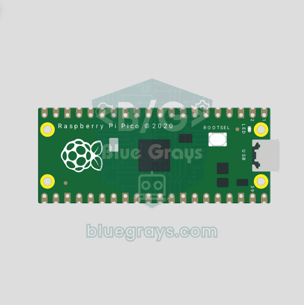
Raspberry Pi Pico Onboard LED Blink (Pico and Pico W)
The opening project of the Raspberry Pi Pico series! We blink the green onboard LED to verify the board works — a classic "Hello World" first experiment. NO external components, just Pico and USB cable. Code is written in MicroPython (the official language backed by Raspberry Pi Foundation). Learn machine.Pin class, Pin.OUT mode, led.on()/off() methods, and time.sleep() in Thonny IDE. Follow every toggle live in the Serial (REPL) output. Also perfect to verify
Raspberry Pi Pico: Controlling an External LED (Breadboard)
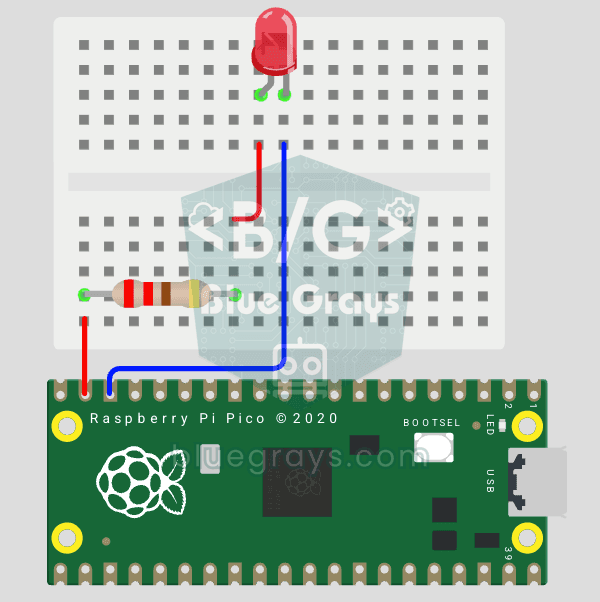
The next step after Pico’s built-in LED: connecting an external LED to the breadboard and controlling it via the GP14 pin. In this project, you’ll learn how to use any of the Pico’s general-purpose GPIO pins as an output, the LED’s polarity (long leg = anode/+, short leg = cathode/–), and why a current-limiting resistor (220Ω) is required. If you don’t include the resistor, excessive current will flow through the LED and it may burn out. The circuit is very simple: Pico GP14 → 220Ω resistor → LE
Using LCD Screen with I2C
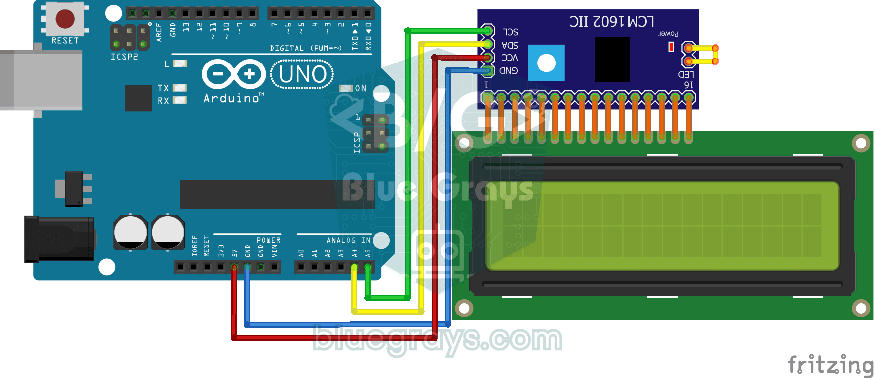
Give your Arduino its own screen and make it write its first message. The two-line LCD screen hooks up with just a few wires; a greeting appears on the top line, then a second message on the bottom li
Print Message on 2x16 LCD Screen
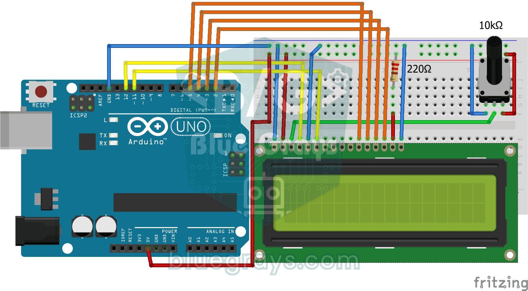
Your first step to writing text on a screen. The two-line LCD screen first shows a waiting message, then writes a greeting on the top line and types a word letter by letter on the bottom line like a t

Bluetooth Controlled Car with L298N
Turn your phone into a remote and drive your own robot car. The Arduino receives commands from a remote-control app on your phone through a Bluetooth module and spins the wheels with a motor driver; t

Obstacle Avoidance Robot
How about building a smart vehicle that finds its own way? The Obstacle Avoidance Robot constantly scans its surroundings thanks to the ultrasonic sensor in front of it. When it encounters an obstacle
Using a WS2812B LED Strip
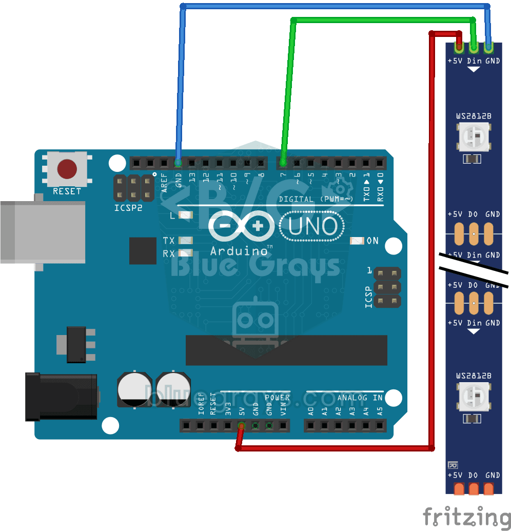
Meet a smart LED strip where you can colour every single light on its own. The Arduino first lights the first five LEDs red, a second later turns the other five blue, then switches them all off and st

Smart Irrigation Station
A gardener that waters your plants on its own, so they don't dry out while you're on vacation. A soil moisture sensor measures how wet the soil is; when it gets dry, the Arduino runs the water pump fo