
Arduino Pro Mini: Programming, Pinout and Low Power on Batteries
What is the Arduino Pro Mini? 3.3 V vs 5 V, programming with USB to TTL, pinout, µA sleep with LowPower, a battery nRF24 sensor and a comparison with the Nano.

The Arduino Pro Mini is an Arduino board with the same ATmega328P processor as the Arduino Uno, but it measures just 18 × 33 mm and has no USB socket. It comes in two versions, 3.3 V / 8 MHz and 5 V / 16 MHz, and you program it with a USB to TTL adapter. Its small size, low price and a sleep current that drops to a few microamps when prepared properly make it the favourite board for wireless sensors that run for months or even years on batteries, wearables and permanent circuits built into an enclosure.
In this guide you'll learn the difference between the two versions and how to tell which one you have, the pinout, the RAW and VCC power pins, and programming with a USB to TTL adapter using auto-reset over DTR. Then you'll put the board to sleep with the LowPower library, cut consumption from milliamps to microamps by removing the power LED and the regulator, and build a battery-powered sensor node that sends the temperature it measures with an nRF24L01. In the last section you'll compare the Pro Mini with the Arduino Nano and see which one to choose when.
What is the Arduino Pro Mini? The 3.3 V and 5 V versions
SparkFun originally designed the Pro Mini; most boards on the market today are clones of the same open design. The board carries the ATmega328P that is the heart of the Uno, a crystal, a small voltage regulator, two LEDs and a reset button; there's no USB chip, no USB socket and no big power circuit. Almost all the code you write for the Uno runs unchanged. The real choice is the board's operating voltage. The ATmega328P needs roughly 3.8 V or more to run reliably at 16 MHz, so the 3.3 V version comes with an 8 MHz crystal and runs at half speed. In return, the 3.3 V version talks to 3.3 V modules such as the nRF24L01, BME280 or an SD card without a level shifter, and can be powered straight from a battery.
| Feature | 3.3 V / 8 MHz version | 5 V / 16 MHz version |
|---|---|---|
| Processor | ATmega328P | ATmega328P |
| Clock speed | 8 MHz | 16 MHz |
| Logic level and VCC | 3.3 V | 5 V |
| RAW input | 3.35–12 V | 5–12 V |
| Program memory | 32 KB (30 KB usable, 2 KB bootloader) | 32 KB (30 KB usable) |
| SRAM / EEPROM | 2 KB / 1 KB | 2 KB / 1 KB |
| Digital pins / PWM | 14 / 6 | 14 / 6 |
| Analog inputs | 8 (A0–A7) | 8 (A0–A7) |
| Upload speed | 57600 baud | 57600 baud |
| Marking on the crystal | 8.000 | 16.000 |
| Best for | Battery-powered sensors, 3.3 V modules | 5 V sensors, relay and LED drivers, speed-critical jobs |
Arduino Pro Mini pinout
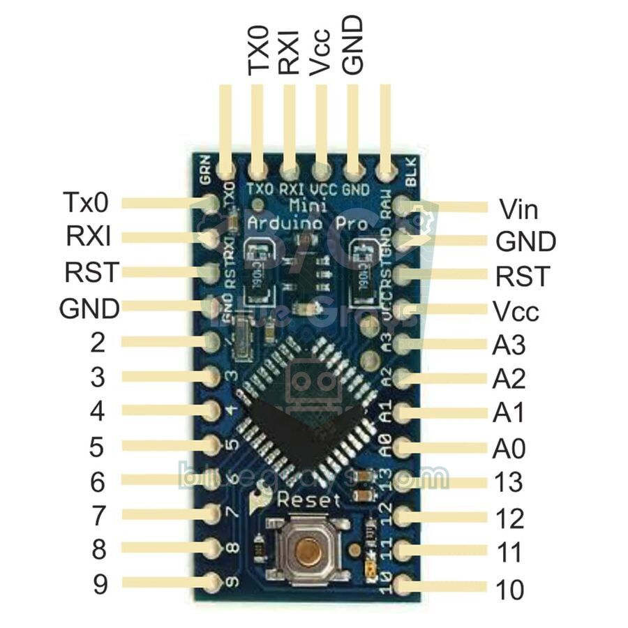
The Pro Mini has 12 pins along each long edge and the six-pin programming header on the short edge. The pin numbers are exactly the same as the Uno's, so you can try a project on the Uno and move it to the Pro Mini with the same code. The only difference to watch is that A4, A5, A6 and A7 aren't on the edge but in separate holes on the inside of the board. To see quickly what's on each pin, you can also check the pinout tool.
| Pin | Function | Note |
|---|---|---|
| D0 (RXI), D1 (TXO) | Serial port (UART) | Wired to the programming header; disconnect any module on these pins while uploading |
| D2, D3 | External interrupt (INT0, INT1) | The best pins for waking the board from sleep |
| D3, D5, D6, D9, D10, D11 | PWM (analogWrite) | Same as the Uno |
| D10, D11, D12, D13 | SPI (SS, MOSI, MISO, SCK) | nRF24L01, SD card, TFT display |
| D13 | Onboard LED | Shared with the SPI clock; the LED flickers while SPI is in use |
| A0–A3 | Analog input or digital pin | On the long edge |
| A4 (SDA), A5 (SCL) | I2C | On the inside of the board; positions can differ on clones |
| A6, A7 | Analog input only | pinMode and digitalRead don't work on these pins |
| RAW | Regulator input | Battery or adapter goes here |
| VCC | Regulated 3.3 V or 5 V | The regulator output; can also be fed directly from a regulated source |
| RST | Reset | Pulling it to GND restarts the board |
| BLK, GND, VCC, RXI, TXO, GRN | Programming header | BLK = GND, GRN = DTR (auto-reset) |
Powering it: RAW, VCC and the regulator
You can power the Pro Mini in two ways. If you connect an unregulated source (a 9 V battery, 3 AA cells or a 7.4 V pack) to the RAW pin, the small regulator on the board brings it down to 3.3 V or 5 V. If you already have a regulated voltage, such as the output of a USB to TTL adapter or 2 AA cells, you feed it straight into the VCC pin and the regulator is bypassed. The onboard regulator is usually a small LDO good for about 150 mA (a MIC5205 on the original, similar parts on clones). That's enough for the board itself and a few sensors, but don't power current-hungry parts like servo motors, long LED strips or Wi-Fi modules from it.
| Source | Pin to use | Note |
|---|---|---|
| 9 V battery or 7–12 V adapter | RAW | The regulator turns the excess into heat; it warms up at 12 V and higher currents |
| 2S Li-ion pack (7.4 V) | RAW | Fine for both versions |
| Single Li-ion cell (3.0–4.2 V) | RAW (3.3 V version) | Not enough for the 5 V version |
| 2 AA cells (2.4–3.2 V) | VCC (3.3 V version) | Bypasses the regulator; ideal for the lowest consumption |
| USB to TTL adapter | VCC | While programming; pick 3.3 V or 5 V to match your version |
| Ready 5 V (USB charger, power bank) | VCC (5 V version) | On RAW the regulator wouldn't have enough headroom |
Programming with a USB to TTL adapter and DTR reset
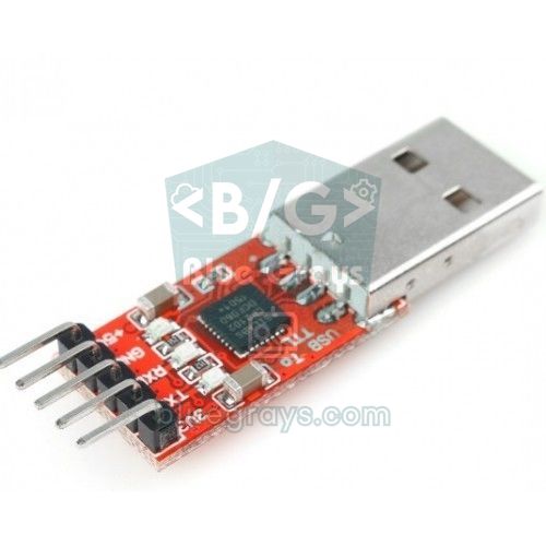
Because there's no USB chip, you need an external USB to TTL adapter (CH340, CP2102 or FT232) to upload code to the Pro Mini. The board has to reset during upload, because the bootloader only accepts a new program in the short window after start-up. When you connect the adapter's DTR pin to the Pro Mini's GRN pin, the 100 nF capacitor on the board turns DTR's falling edge into a short reset pulse and the upload happens without touching the button. The pin order often matches so that the adapter plugs straight onto the header on the board's short edge, but always compare the labels before plugging it in.
| USB to TTL | Pro Mini | Note |
|---|---|---|
| GND | GND / BLK | Common ground |
| VCC (3.3 V or 5 V) | VCC | Set the jumper to match the board version |
| TXD | RXI | Crossed connection |
| RXD | TXO | Crossed connection |
| DTR | GRN | Auto-reset |
- In the Arduino IDE choose Tools > Board > Arduino AVR Boards > Arduino Pro or Pro Mini.
- From Tools > Processor pick the option that matches your board: ATmega328P (3.3V, 8 MHz) or ATmega328P (5V, 16 MHz).
- From Tools > Port choose the adapter's port (something like COM3 on Windows, /dev/cu.usbserial... or /dev/cu.wchusbserial... on macOS).
- Open File > Examples > 01.Basics > Blink and press Upload. The LED on D13 should blink once a second.
- If the LED changes every two seconds, you uploaded to an 8 MHz board with the 16 MHz option; if it changes every half second, it's the other way round. Fix the Processor setting and upload again.
If your adapter has no DTR pin, you time the upload by hand: the moment the IDE finishes compiling and shows "Uploading..." in the output window, press and release the Pro Mini's reset button. If you have no adapter at all, you can temporarily use an Arduino Uno instead: tie the Uno's RESET pin to GND, connect the Uno's pin 0 (RX) to the Pro Mini's RXI and pin 1 (TX) to its TXO. Here the connection is straight, not crossed, because the Uno's USB chip already does the translating in between. If you get the "stk500_getsync(): not in sync" error while uploading, see the Arduino code won't upload article for fixes.
Low power: sleep mode and the LowPower library
A sensor usually takes a reading every five minutes and does nothing for more than 99% of the time in between. Waiting with delay() keeps the processor running at full speed; meanwhile a 3.3 V Pro Mini draws a few milliamps. The ATmega328P's deepest sleep mode is power-down: the clock stops, only the watchdog timer and external interrupts keep working, and the chip's consumption drops to microamps. Rocket Scream's Low-Power library (search for "Low-Power" in the Library Manager) turns these complicated register settings into a single line. The watchdog can count to at most 8 seconds, so longer sleeps are done in a loop; a button or sensor on D2 or D3 can also wake the board.
1// Pro Mini uyku testi: LED yanar, kart 8 sn uyur; D2'deki buton erken uyandırır
2// Pro Mini sleep test: the LED lights, the board sleeps 8 s; a button on D2 wakes it early
3#include <LowPower.h>
4
5const int LED = 13;
6const int WAKE_PIN = 2;                  // INT0, buton GND'ye / button to GND
7volatile bool buttonWake = false;
8
9void onWake() {
10  buttonWake = true;                     // kesmede yalnız bayrak kaldır / only set a flag in the ISR
11}
12
13void setup() {
14  pinMode(LED, OUTPUT);
15  pinMode(WAKE_PIN, INPUT_PULLUP);
16}
17
18void loop() {
19  digitalWrite(LED, HIGH);
20  delay(buttonWake ? 100 : 1000);        // butonla uyandıysa kısa yan / short flash after a button wake
21  digitalWrite(LED, LOW);
22  buttonWake = false;
23
24  attachInterrupt(digitalPinToInterrupt(WAKE_PIN), onWake, LOW);
25  LowPower.powerDown(SLEEP_8S, ADC_OFF, BOD_OFF);   // 8 sn ya da buton / 8 s or the button
26  detachInterrupt(digitalPinToInterrupt(WAKE_PIN));
27}
powerDown() takes three parameters. The first is the sleep time: options range from SLEEP_15MS to SLEEP_8S, plus SLEEP_FOREVER for waking only by interrupt. The watchdog oscillator isn't as precise as a crystal, so an 8-second sleep can drift by about 10% with temperature and voltage; if you need accurate timing, it's better to wake from the alarm output of an RTC module. The second parameter switches the ADC off during sleep. The third disables the brown-out detector (BOD) while sleeping, saving roughly another 20 µA. With attachInterrupt, waking is done on D2 and D3 (other pins need a pin change interrupt); in power-down mode these two pins only wake on a LOW level, which is why the code uses LOW and detaches the interrupt right after waking.
Getting down to microamps by removing the LED and regulator
When you put the board to sleep the processor draws almost nothing, yet you still measure 1–3 mA. Two parts on the board are to blame: the always-on power LED alone uses 1–3 mA, and the regulator draws current for its own internal circuit even with no load (around 80 µA for MIC5205-type regulators). Remove these two parts and the Pro Mini drops to roughly 4–5 µA with the watchdog running, and below 1 µA when it sleeps waiting only for an external interrupt. The table below shows typical values for a 3.3 V / 8 MHz board and the theoretical runtime with the roughly 2000 mAh you can get from two AA cells. To work it out with your own values, use the battery life calculator.
| State (3.3 V / 8 MHz) | Approximate current | Theoretical runtime on 2000 mAh |
|---|---|---|
| Never sleeping, waiting with delay() | 4–5 mA | About 17–21 days |
| Sleeping with LowPower, stock board | 1–3 mA | About 1–3 months |
| Power LED removed | About 80–100 µA (depends on the regulator) | About 2–3 years |
| LED and regulator removed, 8 s watchdog sleep | About 4–5 µA | Over 40 years on paper; in practice the battery's self-discharge is the limit |
| LED and regulator removed, SLEEP_FOREVER | Below 1 µA | Limited by the battery's shelf life |
- First measure the board's sleep current: set the multimeter to the mA range and connect it in series between the battery positive and the board's supply pin. Once the value drops below 1 mA, switch to the µA range.
- Find the power LED: it's the small LED that stays lit whenever the board is powered (the LED on D13 is the one that blinks). Heat its two ends in turn with the soldering iron and lift it off, or remove the series resistor next to it; cutting its trace with a hobby knife also works.
- Find the regulator: it's the small five-legged SOT-23 part near the RAW pin. Add plenty of solder to its legs and heat them all together to lift it off.
- Once the regulator is gone, the RAW pin no longer works. Power the board directly through VCC, with 1.8–3.6 V for the 3.3 V version: two AA cells, a LiFePO4 cell, or a single Li-ion cell behind a regulator that idles at a few microamps, such as the HT7333 or MCP1700.
- Measure the current again. If it isn't around 4–5 µA, the culprit is most likely a connected module: module LEDs and regulators draw current in exactly the same way.
A sensor that runs for months on batteries: NTC and nRF24L01
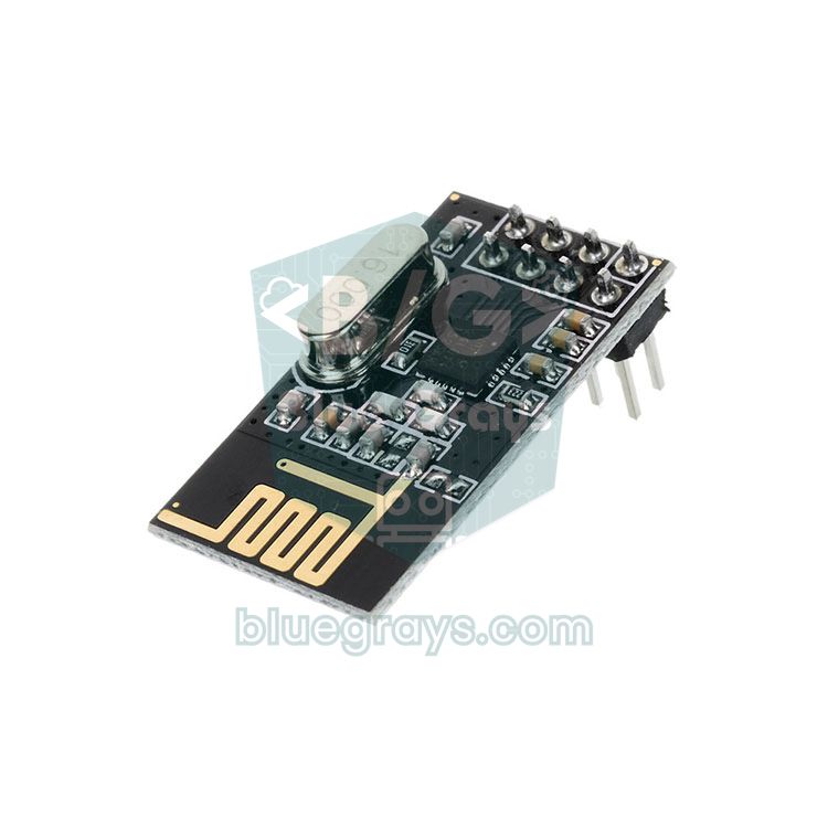
Now let's put it all together: a 3.3 V Pro Mini wakes up every five minutes, measures the temperature with an NTC thermistor plus its own supply voltage, sends the result to a receiver with an nRF24L01 and goes back to sleep. There are two important tricks. First, the NTC's divider isn't connected to 5V or VCC but to a digital pin, so it only draws current during the few milliseconds of the measurement. A 10 kΩ + 10 kΩ divider left on permanently at 3 V would waste 150 µA, thirty times the sleep current. Second, no extra parts are needed for the battery voltage: the code calculates VCC in millivolts by comparing the ATmega328P's internal 1.1 V reference with the supply. Because the NTC measurement is ratiometric, the temperature stays correct even as the supply voltage falls.
| Part | Pro Mini (3.3 V) | Note |
|---|---|---|
| nRF24L01 VCC / GND | VCC / GND | 3.3 V only; put a 10–100 µF capacitor across the module's pins |
| nRF24L01 CE / CSN | D9 / D10 | RF24 radio(9, 10) in the code |
| nRF24L01 SCK / MOSI / MISO | D13 / D11 / D12 | Hardware SPI pins |
| NTC divider supply | D4 → 10 kΩ → A0 | HIGH only while measuring |
| NTC 10 kΩ (B = 3950) | A0 → NTC → GND | Can be extended to the measuring spot |
| Battery | VCC and GND (regulator removed) | 2 AA cells or LiFePO4 |
1// Pille çalışan sıcaklık düğümü: Pro Mini 3,3 V + NTC + nRF24L01
2// Battery-powered temperature node: Pro Mini 3.3 V + NTC + nRF24L01
3#include <SPI.h>
4#include <RF24.h>
5#include <LowPower.h>
6
7RF24 radio(9, 10);                       // CE, CSN
8const byte ADDRESS[6] = "NODE1";         // alıcıyla aynı adres / same address as the receiver
9const int NTC_PWR = 4;                   // bölücüyü besleyen pin / pin that powers the divider
10const int NTC_PIN = A0;
11const int SLEEP_CYCLES = 37;             // 37 x 8 sn = yaklaşık 5 dk / about 5 minutes
12const float R_FIXED = 10000.0;           // sabit direnç / fixed resistor
13const float R0 = 10000.0;                // NTC'nin 25 °C direnci / NTC resistance at 25 °C
14const float BETA = 3950.0;               // NTC B katsayısı / NTC beta coefficient
15const float T0 = 298.15;                 // 25 °C kelvin / 25 °C in kelvin
16const byte UNUSED[] = {2, 3, 5, 6, 7, 8, A1, A2, A3};
17
18struct Packet {
19  uint8_t nodeId;
20  int16_t tempC10;                       // 23,4 °C -> 234
21  uint16_t vccMv;                        // pil gerilimi (mV) / battery voltage (mV)
22  uint16_t counter;
23};
24Packet pkt = {1, 0, 0, 0};
25
26long readVccMv() {
27  ADMUX = _BV(REFS0) | _BV(MUX3) | _BV(MUX2) | _BV(MUX1);  // AVcc'ye karşı 1,1 V / 1.1 V against AVcc
28  delay(2);
29  ADCSRA |= _BV(ADSC);
30  while (bit_is_set(ADCSRA, ADSC)) {}
31  return 1100L * 1024L / ADCW;
32}
33
34float readTempC() {
35  digitalWrite(NTC_PWR, HIGH);           // bölücüye yalnız şimdi güç ver / power the divider only now
36  delay(2);
37  analogRead(NTC_PIN);                   // ilk okumayı at / discard the first reading
38  int raw = analogRead(NTC_PIN);
39  digitalWrite(NTC_PWR, LOW);
40  raw = constrain(raw, 1, 1022);
41  float rNtc = R_FIXED * raw / (1024.0 - raw);     // oransal, VCC'den bağımsız / ratiometric
42  return 1.0 / (1.0 / T0 + log(rNtc / R0) / BETA) - 273.15;
43}
44
45void setup() {
46  for (byte i = 0; i < sizeof(UNUSED); i++) pinMode(UNUSED[i], INPUT_PULLUP);  // boşta kalmasın / no floating pins
47  pinMode(NTC_PWR, OUTPUT);
48  digitalWrite(NTC_PWR, LOW);
49
50  radio.begin();
51  radio.setPALevel(RF24_PA_LOW);
52  radio.setDataRate(RF24_250KBPS);       // daha uzun menzil / longer range
53  radio.setRetries(5, 5);
54  radio.openWritingPipe(ADDRESS);
55  radio.stopListening();
56  radio.powerDown();                     // yaklaşık 1 µA / about 1 µA
57}
58
59void loop() {
60  pkt.vccMv = readVccMv();
61  pkt.tempC10 = (int16_t)(readTempC() * 10.0);
62  pkt.counter++;
63
64  radio.powerUp();
65  delay(5);                              // osilatör otursun / let the oscillator settle
66  radio.write(&pkt, sizeof(pkt));
67  radio.powerDown();
68
69  for (int i = 0; i < SLEEP_CYCLES; i++) {
70    LowPower.powerDown(SLEEP_8S, ADC_OFF, BOD_OFF);
71  }
72}
On each wake-up the node draws a few milliamps (about 10 mA while the nRF24 transmits) for roughly 20–40 ms. Running 40 ms every five minutes adds only about 1 µA to the average; the rest is the sleep current of about 4–5 µA and the nRF24's 1 µA standby current. So the average stays below 10 µA, and on paper two AA cells last for decades; in practice the limit is the battery's shelf life. The counter in the packet lets the receiver spot lost packets, and vccMv tells you when it's time to change the batteries. You can use an Uno or Nano connected to USB as the receiver; with the same RF24 library, call openReadingPipe(1, ADDRESS) and startListening() and read the incoming data with the same Packet definition.
Arduino Pro Mini or Nano?
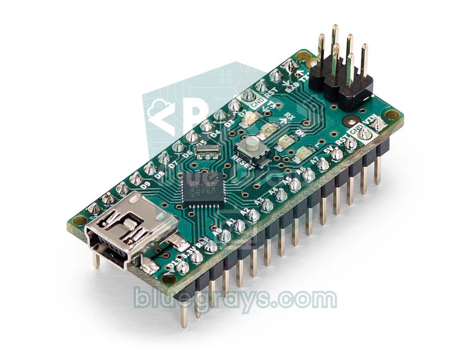
| Feature | Arduino Pro Mini | Arduino Nano (V3) |
|---|---|---|
| Size | 18 × 33 mm | 18 × 45 mm |
| USB | None, needs a USB to TTL adapter | Yes (mini USB, CH340 or FT232) |
| Versions | 3.3 V / 8 MHz and 5 V / 16 MHz | 5 V / 16 MHz only |
| Usable program memory | 30 KB | 30 KB (old bootloader) or 31.5 KB (new bootloader) |
| Analog inputs | 8 (A0–A7) | 8 (A0–A7) |
| Sleep current | 1–3 mA, a few µA once the LED and regulator are removed | In the mA range because of the USB chip, LED and regulator |
| Breadboard | Fits once headers are soldered | Available with headers already fitted |
| Debugging with the Serial Monitor | While the adapter is connected | Any time over the USB cable |
| Best for | Battery-powered, small, permanent projects | Learning, prototyping and USB-connected projects |
In short, the Arduino Nano is more convenient while you're learning and prototyping: plug in the USB cable, upload the code and debug from the Serial Monitor. Once the project is settled, you switch to the Pro Mini if it will run on batteries, has to fit in a small enclosure, or needs to talk to 3.3 V modules without a level shifter. Because the same code runs on both boards, the switch usually means nothing more than changing the Processor setting. In projects with many boards, a single USB to TTL adapter serves all the Pro Minis and the cost per board goes down.
Project ideas with the Arduino Pro Mini
- Wireless temperature network: Put a Pro Mini + nRF24 node in every room and collect the data on a single receiver.
- Battery door and window sensor: With a reed switch on D2, the board sleeps with SLEEP_FOREVER and only wakes to report when the door opens.
- Plant moisture guard: Power the soil moisture sensor from a digital pin and measure once an hour; because the sensor isn't powered all the time, both the battery and the sensor's electrodes last longer.
- Pocket-sized remote: Build a TV or air-conditioner remote with an IR LED and a few buttons; you can adapt the codes from the IR receiver and remote article to the sending side.
- Wearable lights: Sew a few WS2812B LEDs onto a jacket or bag for a moving light effect.
- Data logger: Build a logger hidden in a box that records temperature or battery voltage for weeks with an RTC and an SD card module.
Common mistakes and how to fix them
| Symptom | Likely cause | Fix |
|---|---|---|
| "stk500_getsync(): not in sync" error | TX-RX wired straight, DTR not connected or reset timing missed | Connect TX to RXI and RX to TXO; connect DTR to GRN, or press reset at the "Uploading..." moment |
| Code uploads but timing is twice as slow or fast | Wrong Processor option (16 MHz instead of 8 MHz or vice versa) | Check the crystal marking and upload again with the right option |
| Garbled characters in the Serial Monitor | Wrong Processor, or the baud rate doesn't match the code | Check the Processor and the Serial.begin speed |
| Still more than 1 mA while sleeping | Power LED, regulator or module LEDs | Remove the LED and regulator, power modules from a digital pin |
| A few hundred µA extra while sleeping | Floating inputs | Set unused pins to INPUT_PULLUP |
| nRF24 doesn't work or misses packets | Powered from the 5 V version's VCC, or the supply sags during transmission | Power the module from 3.3 V and add a 10–100 µF capacitor across its pins |
| Board keeps resetting on two AA cells | Voltage has fallen below the 2.7 V BOD threshold | Replace the cells or use a LiFePO4 cell |
| digitalRead(A6) always returns the same value | A6 and A7 are analog-only inputs | Use analogRead or choose another pin |
The Arduino Pro Mini is the cheapest way to take everything you've learned on the Uno and turn it into a fingertip-sized board, a device that lives on a few microamps. Try your code on an Uno or Nano first, then move the same circuit to the Pro Mini. You can build all the LED, button, LDR and sensor projects in the BlueGrays app on an Uno first with step-by-step wiring diagrams and ready-made code, then move them to the Pro Mini using the same pin numbers.
Frequently asked questions
How do you program an Arduino Pro Mini?
Since it has no USB socket, you use a USB to TTL adapter based on a CH340, CP2102 or FT232. Connect GND, VCC, TX → RXI, RX → TXO and DTR → GRN, then choose the "Arduino Pro or Pro Mini" board and the right Processor in the Arduino IDE. If DTR isn't connected, press the reset button by hand as the upload starts.
Should I buy the 3.3 V or the 5 V Pro Mini?
For a battery-powered project that talks to 3.3 V modules such as the nRF24L01, BME280 or an SD card, choose the 3.3 V / 8 MHz version. If you need 5 V sensors, relay modules or more processing speed, the 5 V / 16 MHz version is a better fit. Both run the same code; only the Processor setting differs.
How much current does an Arduino Pro Mini draw?
The 3.3 V / 8 MHz version draws about 4–5 mA while running, and the 5 V / 16 MHz version around 15–20 mA. Put to sleep with LowPower, the stock board still uses 1–3 mA because the power LED and regulator keep running. Once those two parts are removed, sleep current drops to about 4–5 µA with the watchdog on.
Can you plug a USB cable into an Arduino Pro Mini?
No, the Pro Mini has no USB socket or USB chip. You need a USB to TTL adapter to connect it to a computer; with the adapter attached you can power the board, upload code and use the Serial Monitor. If you want to use it straight from USB, the Arduino Nano, which has the same processor, is the more practical choice.
Why don't A6 and A7 work as digital pins on the Pro Mini?
On the ATmega328P, the A6 and A7 channels are wired only to the analog multiplexer and have no digital input/output circuit. That's why pinMode, digitalRead and digitalWrite don't work on them. If you need to connect a digital input such as a button there, use an external pull-up resistor and check with analogRead whether the value is above or below 512.
How long does an Arduino Pro Mini last on batteries?
It depends entirely on the sleep current. A board that never sleeps lasts about three weeks on two AA cells, and one that sleeps with LowPower but is otherwise unmodified runs for 1–3 months. With the power LED and regulator removed, the average current drops below 10 µA and the same cells last for years; then the limit is the batteries' self-discharge.
Projects to build after reading this
See all projects
LED Blink
The very first hello of electronics: switching a single LED on and off. The Arduino turns the LED on and off at short intervals, so the light blinks quickly.

LED Control with a Push Button (Push)
Just like a doorbell: the light stays on as long as you press, and goes off when you let go.

Measuring Light Intensity with an LDR
Want to see how bright your room is as a number? The LDR, a small part that reacts to light, measures the light around it, and the Arduino writes the value to your computer screen every half second.
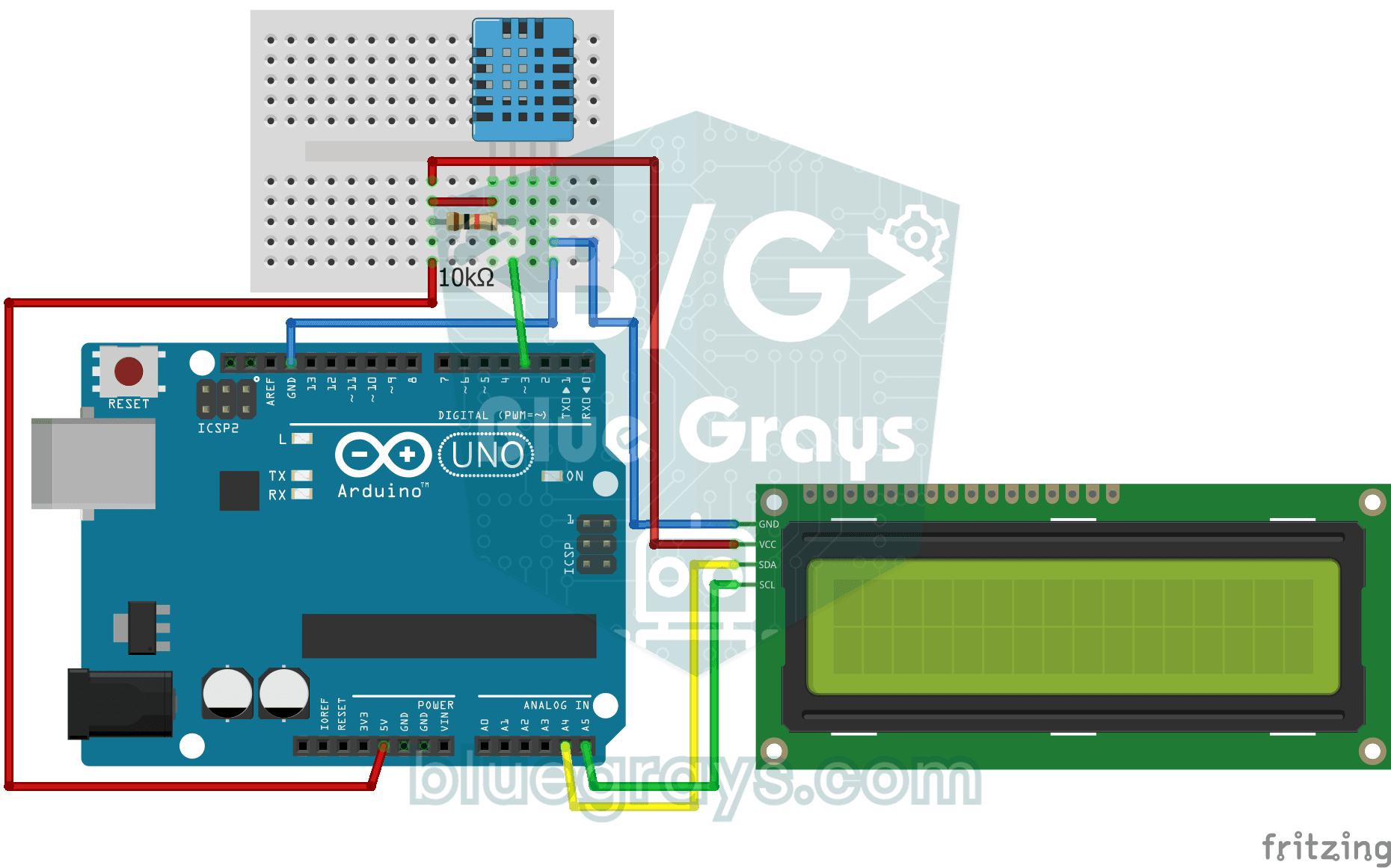
Temperature and Humidity with DHT11
How warm is your room, and is the air humid or dry? The DHT11 sensor measures temperature and humidity, and the Arduino writes the values on a two-line LCD screen, refreshing every couple of seconds.
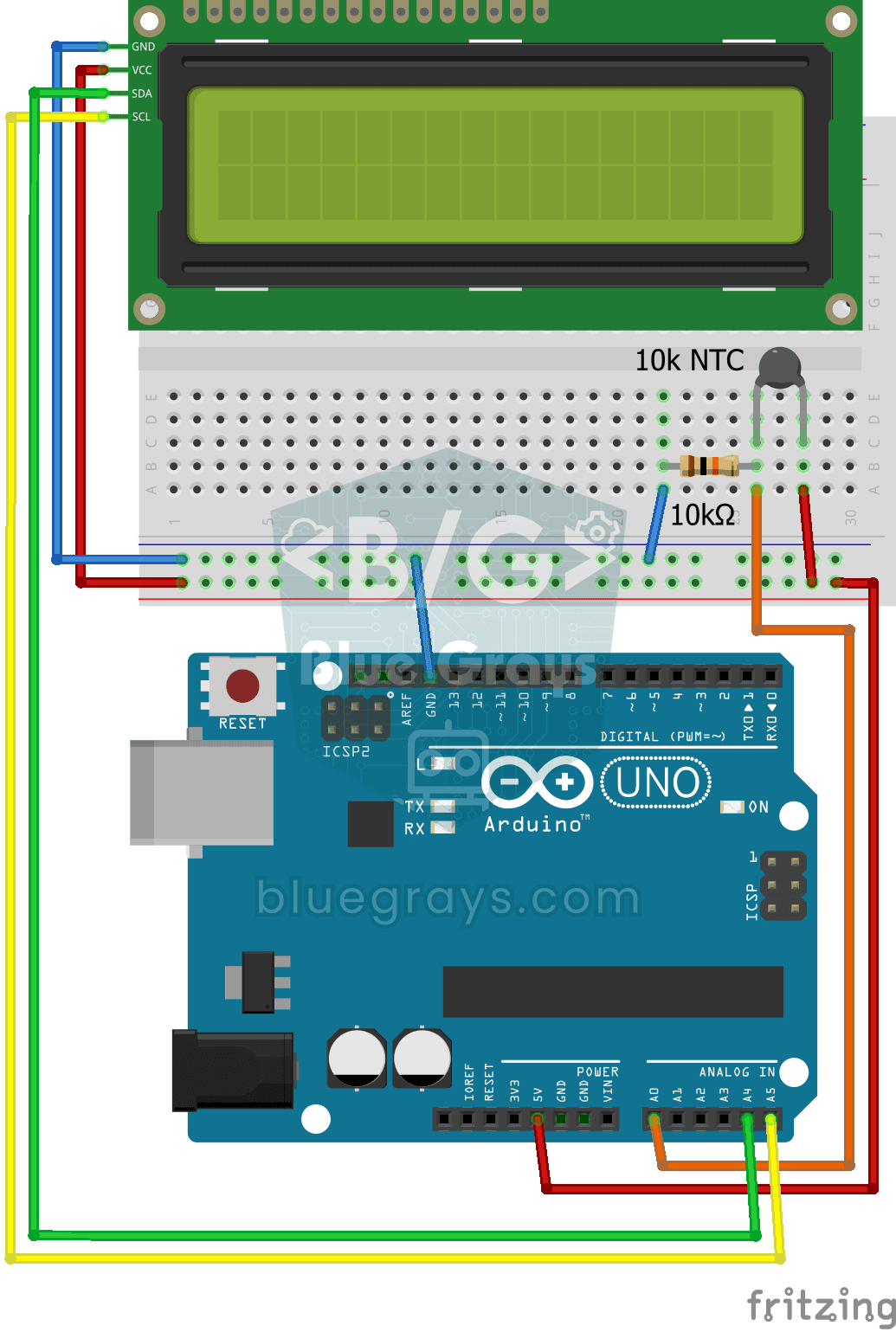
Temperature Measurement with NTC and 2x16 Lcd Display
Measure the temperature around you with a sensor that looks like a tiny bead. This part, called an NTC, lets electricity through more easily as it warms up; the Arduino reads that change, turns it…
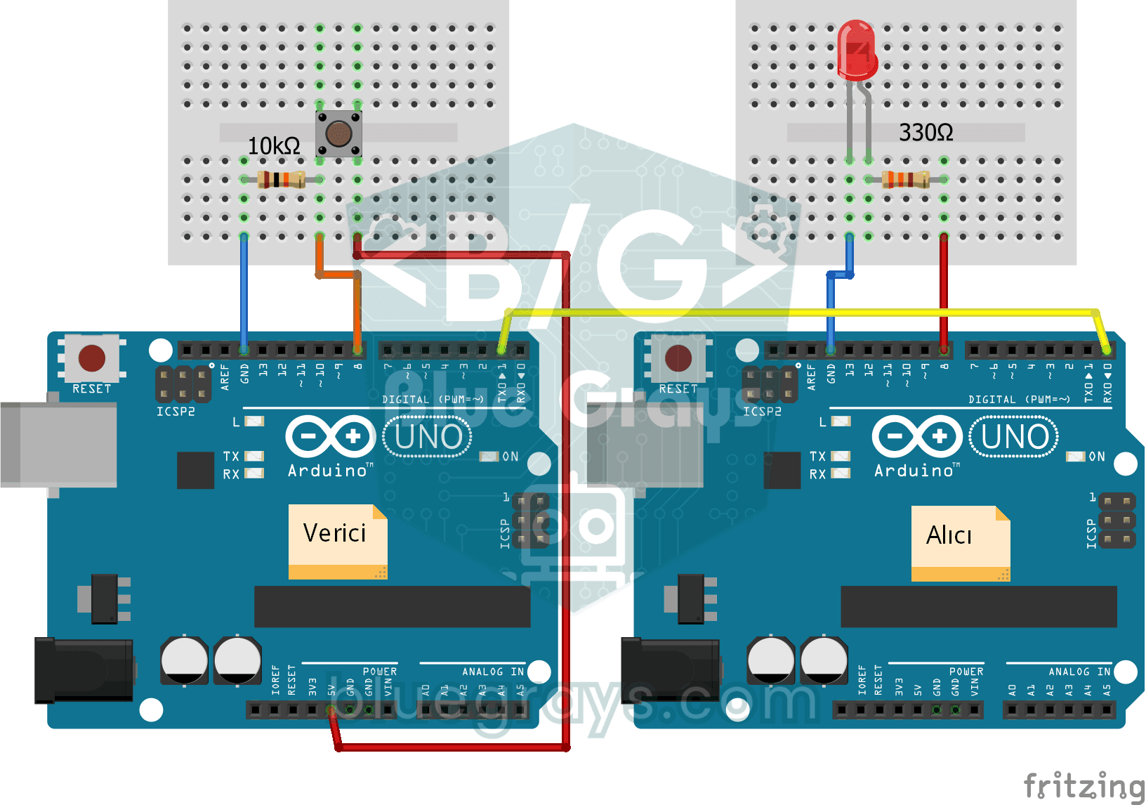
One-Way Communication Between 2 Arduinos
You get two Arduinos talking over a single wire: press the button on one and the LED on the other lights up, press it again and it goes off.
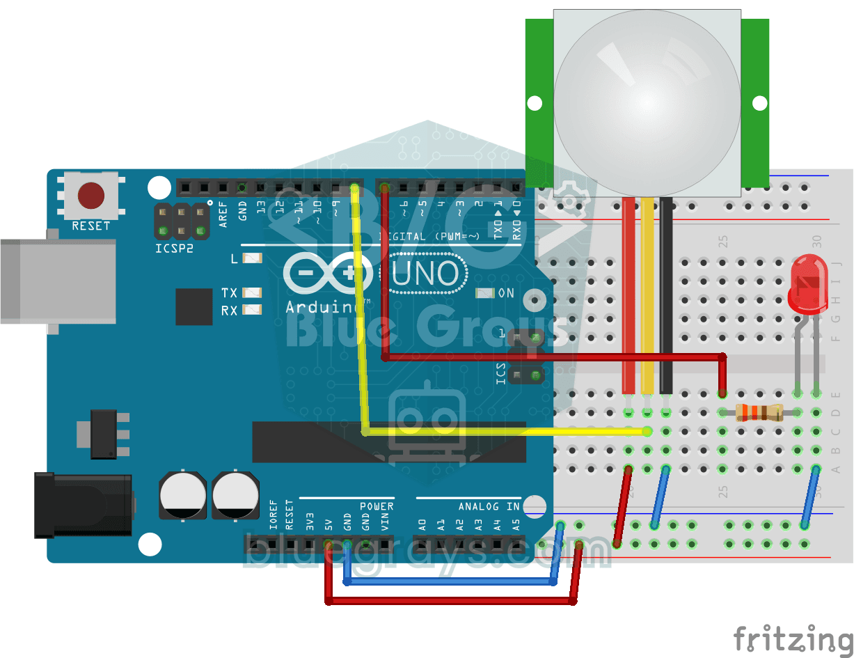
Motion Detector with Motion Sensor
A simple guard that tells you when someone walks into the room. The motion sensor picks up the warmth given off by the human body, and the Arduino keeps the LED on as long as there is movement and…
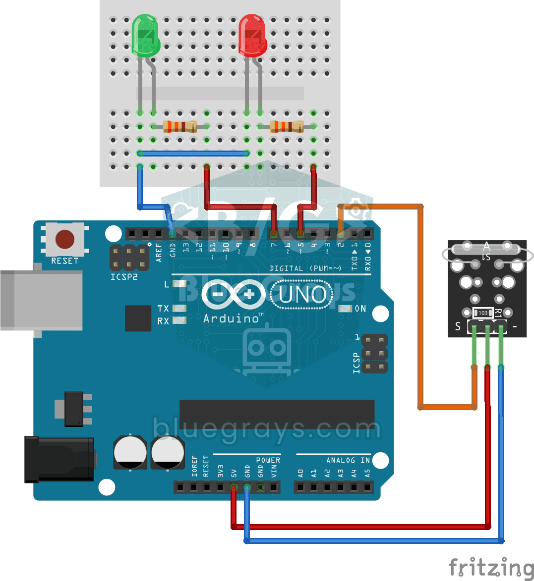
Reed Switch Door Sensor
Tell whether your door is open or closed just by looking at a light. You attach a small magnet to the door and a magnet-sensing switch to the frame; when the door is closed they sit side by side and…