
Arduino Keeps Resetting? Fix Servo, Relay and Freezing Issues
Arduino keeps resetting or freezing? Fix it step by step: servo and relay current, voltage drops, common GND, 470 µF capacitors, RAM overflow and the watchdog.
If your Arduino keeps resetting or freezes after running for a while, the board is almost never broken. In most cases the cause is the power supply: when a servo starts moving, a motor spins up or a relay pulls in, the sudden current draw collapses the 5 V rail for a moment and the processor's low-voltage protection (brown-out) restarts the board. In the remaining cases the culprit is electrical noise from relays and motors, long wires, full RAM, a forgotten watchdog or a computer USB port that cannot deliver enough current.
In this guide you will first learn to tell whether the board is really resetting or just freezing. Then we explain how each cause works with real current and voltage values and show the fixes with code: separate power and a common GND, 100–470 µF capacitors, flyback diodes, fixed buffers instead of String, and the watchdog. You will also find a diagnostic sketch that measures the Arduino's own supply voltage and free RAM, a step-by-step troubleshooting table from symptom to fix, and examples that read the reset reason on the ESP32 and the Raspberry Pi Pico.
Reset or freeze? Identify the symptom first
A resetting Arduino runs the program from the very beginning, as if you had unplugged and replugged the USB cable: setup() runs again, the servo returns to its start angle, the LCD shows its startup text again and the startup message reappears in the Serial Monitor. A frozen Arduino, on the other hand, does not respond to anything; the LEDs stay in their last state, serial output stops and the board waits like that until you press the reset button. Since the causes and fixes are different, start by finding out which one you have. The easiest way is to add a Serial.println("STARTED") line to setup() and leave the Serial Monitor open.
| Symptom | Reset | Freeze |
|---|---|---|
| Does setup() run again? | Yes, the startup message appears again | No |
| Serial output | Stops, then starts again with the startup message | Stops and never comes back |
| Outputs and LEDs | Turn off briefly, then return to their initial state | Stay stuck in their last state |
| Most common cause | Voltage drop, noise, watchdog | Endless loop, hung I2C bus, corrupted RAM |
| Check first | Power, GND and wiring | Code, memory usage and sensor wiring |
Why does an Arduino reset itself? Reset sources
Only a few sources can restart the ATmega328P processor on the Arduino Uno and Nano, and each one has its own trigger. When the supply voltage falls below a certain threshold, the brown-out detector (BOD) kicks in; on the Uno and Nano the fuse settings put this threshold at 2.7 V. Anything that pulls the RESET pin LOW also restarts the board: the reset button, the computer's DTR signal or noise picked up by a long wire connected to that pin. There is also a case that looks like a reset but is not one: corrupted memory makes the program jump to address 0 and the code starts over, but because the hardware peripherals are not reset, the board begins to behave strangely.
| Reset source | What triggers it? | Typical symptom |
|---|---|---|
| Power-on (POR) | Plugging in the cable, power dropping out completely | Normal startup |
| External reset (RESET pin) | Reset button, opening the Serial Monitor (DTR), noise on the RESET pin | Restarts when the port is opened or a wire is touched |
| Brown-out (BOD, 2.7 V) | Inrush current of a servo, motor, relay or LED strip, a weak battery | Resets the moment the load moves |
| Watchdog | wdt_reset() was not called in time | Resets at regular intervals (e.g. exactly every 2 seconds) |
| Software crash | Array out of bounds, RAM overflow, bad pointer | Random reset or freeze after minutes or hours |
Servo, motor and relay current: how a voltage drop causes a reset
An SG90 servo draws 100–250 mA while moving, but at startup and when its arm is loaded the current jumps above 0.5 A. A computer's USB 2.0 port supplies at most 500 mA, and the fuse on the Uno's USB line works at the same limit. When the servo, the board's own 50 mA and a few modules exceed this limit, the port or the fuse limits the current, the 5 V rail collapses for an instant, and if the voltage drops below 2.7 V the BOD resets the board. The sneakier case is when the voltage stays between 2.7 V and about 3.8 V: according to the ATmega328P datasheet, the chip needs roughly 3.8 V to run safely at 16 MHz. In this grey zone the BOD does not trigger, but the processor runs outside its speed limit, so the board may freeze instead of resetting, produce garbage values, or I2C displays and sensors may lock up internally.
| Load | Normal current | Peak current | Powered from the Uno's 5V pin? |
|---|---|---|---|
| SG90 micro servo | 100–250 mA | 0.5 A and more (startup, load) | Only a single servo with a light load |
| MG996R servo | 0.5–0.9 A | Up to 2.5 A | No, a separate 5–6 V supply is a must |
| TT gear DC motor | 70–250 mA | ~1 A (startup, stall) | No, motor driver and separate supply |
| 5 V relay module (single channel) | 70–90 mA | Short pulse as the coil energizes | 1–2 channels yes, 4 or more from a separate supply |
| WS2812B LED (each) | ~20 mA (one color at full brightness) | 60 mA (full white) | No; 30 LEDs at full white need 1.8 A |
Wires matter too. The thin jumper wires used in breadboard projects are usually 26–28 AWG, and 28 AWG copper wire has a resistance of about 0.21 Ω per meter. If you power the servo through two 20 cm wires (0.4 m out and back) and a breadboard, the wires add about 0.085 Ω and four breadboard contacts add around 0.2 Ω together. By Ohm's law (V = I × R), a 1 A servo pulse loses about 0.3 V across these 0.29 Ω. A thin, long USB cable, the fuse and the protection parts on the board add roughly another half ohm; during the same pulse the Arduino's 5 V rail drops below 4.5 V, and if the computer port starts limiting the current, the drop is much deeper. You can work out the drop in your own circuit with the Ohm's law calculator.
Fix 1: Separate power supply and common GND
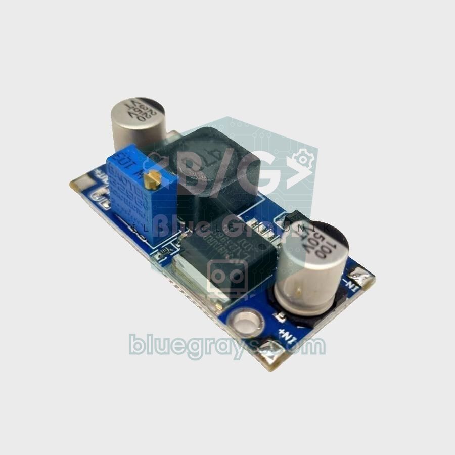
- Choose a separate supply for servos and motors: for servos, a 5–6 V adapter that delivers at least 1 A per servo (2–3 A for an MG996R), a 4×AA NiMH pack or an LM2596 buck module set to 5–6 V.
- Connect the supply's positive only to the servos' red wires or to the motor driver's power input; do not connect this line to the Arduino's 5V pin.
- Connect the supply's negative (GND) both to the load and to the Arduino's GND pin. Without this common GND the signal pin's voltage has no reference; the servo jitters or does not move at all.
- Join the GNDs at a single point next to the supply (star grounding). Motor current must not return through the Arduino and its GND traces; otherwise the Arduino's GND level shifts with every motor pulse.
- Power the Arduino from its own input: USB, the DC jack (7–12 V) or a regulated 5 V. That way the processor is not affected even if the servo supply sags.
- Finally, measure between the Arduino's 5V and GND pins while the servo moves, or run the diagnostic sketch below; the voltage should not drop below 4.75 V.
Fix 2: Capacitors (100–470 µF) and diodes
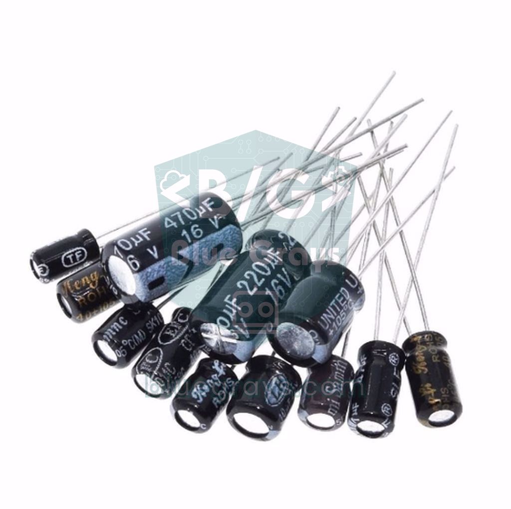
An electrolytic capacitor works like a small energy store sitting next to the load: when the servo demands a sudden current, it supplies that current itself until the wires and the power supply catch up. The formula ΔV = I × Δt / C tells you how much it helps. A 470 µF capacitor lets the voltage drop only 0.21 V during a 1 A pulse lasting 100 µs; if the same pulse lasts 1 ms, the drop is 2.1 V. In other words, a capacitor swallows short pulses and the noise from motor brushes, but it does not replace an inadequate supply. Put 470–1000 µF on the servo line and 100 µF between the Arduino's 5V and GND, and add a 100 nF ceramic capacitor marked 104 next to each one for high-frequency noise. Use the capacitor code tool to read the markings and the capacitor network calculator to find the total of capacitors in parallel; the differences between types are covered in What is a capacitor?.
| Where? | Value | Why? |
|---|---|---|
| Servo supply line, next to the servo | 470–1000 µF / 10–16 V electrolytic + 100 nF | Softens the startup pulse |
| Across the two terminals of a DC motor | 100 nF ceramic | Filters the noise from brush sparks |
| Between the Arduino's 5V and GND | 100 µF electrolytic + 100 nF | Protects the processor's rail from short dips |
| WS2812B strip input | 1000 µF / 10 V | Handles the inrush current and color-change pulses |
| Sensor and module supply pins | 100 nF ceramic | Filters noise carried by long wires |
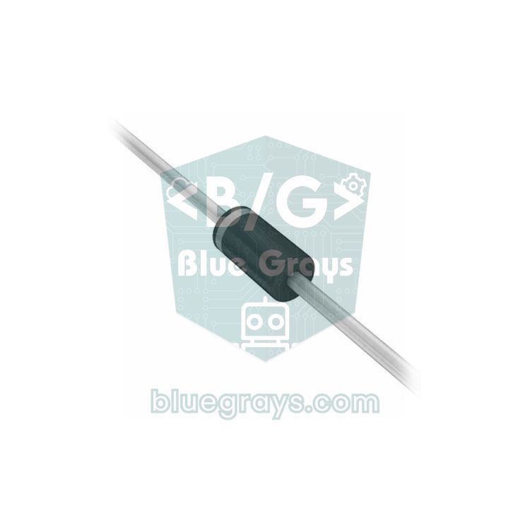
Relay coils, motors and solenoids are all inductors. When the current through them is cut suddenly, the coil resists the change and produces a short voltage spike of tens or even hundreds of volts, far above the supply voltage. This spike spreads along the line and resets the Arduino, and it can also destroy the driver transistor or the pin. The fix is a flyback diode connected in parallel with the coil, in reverse: the striped cathode end of a 1N4007 goes to the positive side, the other end to the side that leads to the transistor. Ready-made relay modules already include this diode; if you use a bare relay, a solenoid or a motor driven by a transistor or MOSFET, you must add the diode yourself. For motors with PWM speed control, the faster 1N5819 Schottky diode gives better results. For details see What is a diode? and using a MOSFET with Arduino.
Noise, relay contacts and long wires
If the board resets exactly when a relay switches off, the problem is noise, not power. When a relay switches off a water pump, a fan, a fluorescent lamp or a contactor, a small arc forms between the contacts and this arc radiates broadband electromagnetic noise. The noise couples into nearby sensor wires, the RESET line and the I2C lines, resetting the processor or locking up a module. To prevent this, use an optocoupler relay module, remove the JD-VCC jumper and power the relay coils from a separate 5 V supply; this keeps the coil current and the noise away from the Arduino's rail. With inductive mains loads, an RC snubber (100 Ω + 100 nF, X2 class) or a varistor across the contacts or the load greatly suppresses the arc. You will find the wiring details in What is a relay module? and the idea behind isolation in What is an optocoupler?.
- Keep I2C short: I2C was designed for short distances on a circuit board. Keep the SDA and SCL wires under 50 cm; on longer runs lower the pull-up resistors from 4.7 kΩ to 2.2 kΩ and leave the speed at 100 kHz.
- Use twisted wires: Twist each signal wire together with a GND wire; the twisted pairs in a network cable are ideal for this.
- Separate power and signal: Do not run sensor wires parallel to motor, relay or mains wires; if they have to cross, cross them at a right angle.
- Leave the RESET pin alone: A long wire on the RESET pin acts like an antenna and resets the board when touched or when a nearby motor runs. If you need an external reset button, keep its wire short.
- Ferrites and an enclosure: Ferrite rings on motor wires and a metal enclosure reduce high-frequency noise.
- Add a timeout: If noise locks up the I2C bus, the Wire library waits forever by default and the board freezes. The code below prevents this freeze with a timeout.
1#include <Wire.h>
2
3const uint8_t ADDR = 0x27;   // örnek: I2C LCD adresi / example: I2C LCD address
4
5void setup() {
6  Serial.begin(9600);
7  Wire.begin();
8  Wire.setWireTimeout(25000, true);   // 25 ms; takılırsa I2C birimini sıfırla / reset the I2C unit on timeout
9}
10
11void loop() {
12  Wire.beginTransmission(ADDR);
13  byte err = Wire.endTransmission();  // 0 = cihaz cevap verdi / 0 = device answered
14
15  if (Wire.getWireTimeoutFlag()) {    // hat kilitlendi ama program donmadı / bus hung, sketch did not freeze
16    Serial.println(F("I2C zaman asimi / I2C timeout"));
17    Wire.clearWireTimeoutFlag();
18  } else if (err != 0) {
19    Serial.print(F("I2C hatasi / I2C error: "));
20    Serial.println(err);              // 2 = cihaz yok, 5 = zaman aşımı / 2 = no device, 5 = timeout
21  }
22  delay(1000);
23}
RAM overflow and using String
The Arduino Uno has only 2 KB of SRAM, and this small space is shared by global variables, dynamic memory (the heap) and the stack used by function calls. If you see the warning Low memory available, stability problems may occur. at the end of compiling, the board will most likely crash after a while. The sneakiest cause is the String class: every concatenation allocates a new chunk on the heap, the old one is freed, and over time memory becomes full of holes. One day the stack collides with the heap and the program resets or freezes at a random moment. Because this usually shows up after minutes or hours, it is easy to tell apart from power problems. Keep constant text in flash with the F() macro, use fixed-size char arrays and snprintf() instead of String, and do not declare large local arrays inside functions. The code below prints the free RAM every second; if the value keeps dropping, you have a memory leak. The full story is in Arduino out of memory.
1extern int __heap_start, *__brkval;
2
3// Heap ile stack arasındaki boş RAM / free RAM between heap and stack
4int freeRam() {
5  int v;
6  return (int)&v - (__brkval == 0 ? (int)&__heap_start : (int)__brkval);
7}
8
9char line[32];             // sabit tampon, bir kez ayrılır / fixed buffer, allocated once
10unsigned long counter = 0;
11
12void setup() {
13  Serial.begin(9600);
14}
15
16void loop() {
17  counter++;
18  // Kaçın / avoid: String s = "Sayac: " + String(counter) + " sn";
19  snprintf(line, sizeof(line), "Sayac: %lu sn", counter);  // heap kullanmaz / no heap use
20  Serial.println(line);
21
22  Serial.print(F("Bos RAM / free RAM: "));  // F(): metin flaşta kalır / text stays in flash
23  Serial.println(freeRam());                // sürekli azalıyorsa sızıntı var / steady drop = leak
24  delay(1000);
25}
Watchdog: a safety belt against freezes
The watchdog timer is a counter inside the processor that runs independently on its own 128 kHz oscillator. Your program has to feed it regularly with wdt_reset(); if it is not fed within the set time (between 15 ms and 8 seconds), the watchdog resets the board. This way a hung I2C bus, a function stuck in an endless loop or a sensor reading corrupted by noise cannot freeze the board forever; it recovers within a few seconds. Remember that the watchdog is a safety belt, not a repair: it does not fix power or memory problems, it only lets a project running in the field recover on its own. Choose a timeout clearly longer than the longest operation in your code; in code that contains delay(3000), a 2-second watchdog will reset the board over and over.
1#include <avr/wdt.h>
2
3const int LED_PIN = 13;
4
5void setup() {
6  MCUSR = 0;          // reset bayraklarını temizle / clear reset flags
7  wdt_disable();      // açılışta watchdog kapalı / watchdog off during startup
8  Serial.begin(9600);
9  pinMode(LED_PIN, OUTPUT);
10  Serial.println(F("Basladi / started"));
11  delay(500);
12  wdt_enable(WDTO_2S);  // 2 sn içinde beslenmezse reset / reset if not fed within 2 s
13}
14
15void loop() {
16  digitalWrite(LED_PIN, !digitalRead(LED_PIN));
17  delay(250);
18
19  // Seri Monitör'den 'x' gönder: takılmayı taklit eder / send 'x' to simulate a hang
20  if (Serial.available() && Serial.read() == 'x') {
21    Serial.println(F("Sonsuz donguye girildi / stuck in a loop"));
22    while (true) {}     // wdt_reset() yok: 2 sn sonra reset / no wdt_reset(): reset after 2 s
23  }
24
25  wdt_reset();          // her turda besle / feed it every loop
26}Diagnostic sketch: let the Arduino measure its own voltage and RAM
A multimeter is too slow to see millisecond voltage dips. Instead, you can use the Arduino itself as a simple measuring instrument: the code below uses the ADC to measure the chip's internal 1.1 V reference and calculates the supply voltage from it, about 9000 times per second, and prints the lowest value of each second. It also increments a counter in EEPROM at every boot, so even if you open the Serial Monitor later you can see how many times the board has restarted. As a test load it moves the servo on D9 between 0 and 180 degrees every 2 seconds; if you have your own project, you can add the measuring part to its code. Open the Serial Monitor at 115200 baud.
1// Reset teşhis kodu (Uno, Nano) / reset diagnostic sketch (Uno, Nano)
2#include <EEPROM.h>
3#include <Servo.h>
4
5Servo servo;
6extern int __heap_start, *__brkval;
7
8int freeRam() {
9  int v;
10  return (int)&v - (__brkval == 0 ? (int)&__heap_start : (int)__brkval);
11}
12
13// Besleme gerilimini dahili 1,1 V referansla ölç / measure supply voltage against the internal 1.1 V reference
14long readVcc() {
15  ADMUX = _BV(REFS0) | _BV(MUX3) | _BV(MUX2) | _BV(MUX1);
16  ADCSRA |= _BV(ADSC);                  // ölçümü başlat / start a conversion
17  while (bit_is_set(ADCSRA, ADSC)) {}   // bitmesini bekle / wait until it is done
18  return 1125300L / ADC;                // 1100 mV × 1023 / okuma → mV / reading → mV
19}
20
21long minVcc = 9999;
22unsigned long lastPrint = 0, lastMove = 0;
23bool sideA = false;
24
25void setup() {
26  Serial.begin(115200);
27  uint16_t boots;
28  EEPROM.get(0, boots);                 // açılış sayacı / boot counter
29  if (boots == 0xFFFF) boots = 0;       // boş EEPROM / blank EEPROM
30  EEPROM.put(0, ++boots);
31  Serial.print(F("BASLADI / STARTED  acilis no / boot #"));
32  Serial.println(boots);
33
34  servo.attach(9);                      // test yükü: servo D9'da / test load: servo on D9
35  readVcc();                            // ilk ölçümü at / discard the first reading
36  delay(5);
37}
38
39void loop() {
40  long v = readVcc();                   // saniyede ~9000 ölçüm / ~9000 samples per second
41  if (v < minVcc) minVcc = v;
42
43  if (millis() - lastMove >= 2000) {    // 2 sn'de bir servoyu oynat / move the servo every 2 s
44    lastMove = millis();
45    sideA = !sideA;
46    servo.write(sideA ? 180 : 0);
47  }
48
49  if (millis() - lastPrint >= 1000) {
50    lastPrint = millis();
51    Serial.print(F("sn/s: "));
52    Serial.print(millis() / 1000);
53    Serial.print(F("  min Vcc (mV): "));
54    Serial.print(minVcc);
55    Serial.print(F("  bos RAM / free RAM: "));
56    Serial.println(freeRam());
57    minVcc = 9999;                      // her saniye sıfırla / reset every second
58  }
59}
Read the results like this: on a healthy Uno powered from USB, the lowest value stays between 4.6 and 5.1 V. If the value drops below 4.5 V every time the servo moves and the resets coincide with those moments, the problem is power. If the boot number keeps increasing while the voltage stays steady, look for noise or a software cause; if the free RAM keeps decreasing at the same time, you have a memory leak. The internal 1.1 V reference can differ by about 10% from chip to chip, so compare the reading once with a multimeter: if the multimeter shows 4.95 V while the code prints 5.10 V, change the 1125300 constant to 1125300 × 4.95 / 5.10 ≈ 1092200. Remove the EEPROM counter from the code when you are done; EEPROM cells are rated for about 100,000 writes.
Step-by-step troubleshooting table: symptom, cause, fix
Read the table from top to bottom; the first rows are the most common causes. Change only one thing at a time and run the diagnostic sketch again. If you change three things at once, you will not know which one solved the problem, and the same fault will come back in your next project.
| Symptom | Likely cause | How to confirm | Fix |
|---|---|---|---|
| Resets when a servo or motor moves | Inrush current collapses the 5 V rail | Lowest voltage in the diagnostic sketch drops below 4.5 V | Separate 5–6 V supply, common GND, 470–1000 µF |
| Resets when a relay releases, not when it pulls in | Contact arc and coil spike (noise) | Problem disappears when the relay's load is removed | Separate supply via JD-VCC, snubber or varistor, flyback diode |
| Starts over when the Serial Monitor opens | DTR auto-reset (normal behavior) | STARTED appears every time the port opens | Not a fault; if needed, 10 µF between RESET and GND |
| Resets only on the computer, fine on an adapter | USB port or hub cannot supply enough current | Fixed by another port and a short, thick cable | Use a rear port or a powered hub, power loads separately |
| Resets on movement when running on a 9V battery | High internal resistance, voltage collapses | Vin drops below 7 V during movement | 6×AA or a 2S 18650 pack |
| Resets or freezes after minutes or hours | RAM overflow, String fragmentation | Free RAM keeps decreasing | F(), char arrays, snprintf, small local arrays |
| Resets at exact regular intervals | Watchdog is not fed in time | Reset interval equals the watchdog timeout | Add wdt_reset() or lengthen the timeout, avoid long delay() |
| On a Nano, code never starts after a watchdog reset | Old bootloader watchdog bug | Board only uploads with the Old Bootloader option | Burn the Optiboot bootloader |
| Random freezes when a long sensor cable is attached | I2C bus locks up from noise | Wire timeout flag is set | Short twisted wires, 2.2 kΩ pull-ups, setWireTimeout, watchdog |
| Resets when you bring your hand close or touch it | Long wire on the RESET pin, static electricity | Fixed when the wire is removed | Keep the RESET line short, put the circuit in an enclosure |
| Regulator gets very hot, then resets | High current with 12 V on the jack, regulator thermal shutdown | Regulator too hot to touch | 7–9 V adapter or a 5 V buck module |
| Board does not power up or the port disappears | Short circuit, USB fuse tripped | Board powers up with the modules removed | Find the short, check whether the board is damaged |
USB port cannot supply enough current, and the Serial Monitor reset
A computer's USB 2.0 port supplies 500 mA and a USB 3.0 port 900 mA; but since the Uno's USB fuse limits at 500 mA, a USB 3.0 port gives you no extra current. An unpowered USB hub shares one port's current among all its devices, front-panel ports lose voltage through thin internal cables, and laptops running on battery may power their ports weakly in power-saving mode. Plug the board directly into a rear port with a short, good-quality cable. There is also a reset that is not a fault: the Uno and Nano reset themselves through the DTR signal when the Serial Monitor or a Python program opens the port, and this is the very feature that makes uploading possible. If you communicate from Python, wait 2 seconds after opening the port (Arduino and Python serial communication). If you want to disable the reset completely, put a 10 µF capacitor between RESET and GND and remove it when uploading. Serial port details are in Arduino Serial Monitor.
ESP32 keeps resetting: reading the reset reason
The ESP32 is even more sensitive to the same problems because it runs on 3.3 V and draws around 240 mA during Wi-Fi transmission, more in short peaks; Espressif recommends a supply that can deliver at least 500 mA. The good news is that the ESP32 tells you itself why it restarted. The message Brownout detector was triggered in the Serial Monitor means a voltage drop, and the rst:0xf (RTCWDT_BROWN_OUT_RESET) or Guru Meditation Error lines at boot show the reset reason. The code below reads the same information with esp_reset_reason() and turns it into readable text. On the ESP32 the EN button switches the chip completely off and on, so a reset with this button also shows up as a power-on. For all the messages and their fixes, see ESP32 brownout and Guru Meditation errors.
1#include <esp_system.h>
2
3// Reset sebebini yazıya çevir / turn the reset reason into text
4const char* reasonText(esp_reset_reason_t r) {
5  switch (r) {
6    case ESP_RST_POWERON:   return "Guc acilisi ya da EN tusu / power-on or EN button";
7    case ESP_RST_SW:        return "Yazilimla (ESP.restart) / software restart";
8    case ESP_RST_PANIC:     return "Cokme (Guru Meditation) / panic";
9    case ESP_RST_INT_WDT:   return "Kesme watchdog'u / interrupt watchdog";
10    case ESP_RST_TASK_WDT:  return "Gorev watchdog'u / task watchdog";
11    case ESP_RST_WDT:       return "Diger watchdog / other watchdog";
12    case ESP_RST_DEEPSLEEP: return "Derin uykudan uyanma / deep sleep wake-up";
13    case ESP_RST_BROWNOUT:  return "Gerilim dusmesi (brownout) / brownout";
14    default:                return "Bilinmeyen / unknown";
15  }
16}
17
18void setup() {
19  Serial.begin(115200);
20  delay(500);
21  esp_reset_reason_t r = esp_reset_reason();
22  Serial.print("Reset nedeni / reset reason: ");
23  Serial.println(reasonText(r));
24}
25
26void loop() {
27  Serial.print("Calisma suresi / uptime (s): ");
28  Serial.println(millis() / 1000);
29  delay(5000);
30}
Raspberry Pi Pico: reset cause and watchdog (MicroPython)
Thanks to its buck-boost regulator, the Raspberry Pi Pico runs on any voltage between 1.8 and 5.5 V on the VSYS pin, so it tolerates voltage dips better than an Arduino. Still, if you connect a servo to the VBUS pin, which carries the USB 5 V, the current is drawn straight from the computer's port, and if the port collapses the Pico goes down too; you should also not draw more than 300 mA in total from the 3V3 pin. The Pico's reset pin, RUN, is pulled up by an on-chip resistor of about 50 kΩ; connecting a long wire to it leaves an open door for noise, just like the RESET pin on the Arduino. In MicroPython, machine.reset_cause() returns only two values on the Pico: PWRON_RESET for power-on or the RUN pin, and WDT_RESET for the watchdog or machine.reset(). The watchdog can be set to at most 8388 ms and cannot be stopped once started; it keeps resetting the board even if you stop the program in Thonny. That is why you should put a 3-second wait at the start of your code.
1import machine, time
2from machine import Pin
3
4time.sleep(3)   # Thonny durdurabilsin diye bekle / wait so Thonny can stop the script
5
6neden = machine.reset_cause()
7if neden == machine.WDT_RESET:
8    print("Watchdog ya da machine.reset() / watchdog or machine.reset()")
9else:
10    print("Guc acilisi ya da RUN pini / power-on or RUN pin")
11
12led = Pin("LED", Pin.OUT)          # Pico ve Pico W dahili LED / onboard LED
13wdt = machine.WDT(timeout=5000)    # 5 sn; RP2040'ta en fazla 8388 ms / max 8388 ms on RP2040
14
15sayac = 0
16while True:
17    led.toggle()
18    sayac += 1
19    print("Calisiyor / running", sayac)
20    wdt.feed()                     # her turda besle / feed it every loop
21    time.sleep(1)
The right power layout for your project
- Robot car: Power the motors from a 2S 18650 pack through an L298N or L9110S and put a 100 nF capacitor across the motor terminals; the build is in building an Arduino robot car.
- Servo robot arm: For four or more servos, use a 5–6 V supply that delivers at least 3–5 A and add 1000 µF to the servo line; for choosing parts see MG996R servo and Arduino robot arm.
- Irrigation system with a pump and relay: Power the pump from a separate supply, isolate the relay with JD-VCC and keep long sensor wires away from the pump cable (soil moisture sensor).
- LED strips and NeoPixels: Budget about 2 A for every 30 LEDs, and put 1000 µF at the strip input and a 300–500 Ω resistor on the data line (WS2812B NeoPixel).
- Driving DC motors: Do not forget the flyback diode on every motor you drive with a transistor or MOSFET; for ready-made driver boards see DC motor control with the L298N.
- Sensor station in the field: Enable the watchdog, set an I2C timeout and take power from an efficient source such as the LM2596 step-down converter.
An Arduino that resets itself is annoying, but there is almost always a measurable, fixable cause: first identify the symptom, then measure the voltage and RAM with the diagnostic sketch, then separate the power, join the GNDs, add the capacitor and the diode, and secure the project with the watchdog if needed. Once you have this setup in place, your servo, motor and relay projects will run for days without trouble. In the BlueGrays app you will find servo motor control, a Bluetooth car with the L298N, an obstacle-avoiding robot, 220 V lamp control and a smart irrigation station, with circuit diagrams that show the correct power connections and step-by-step code.
Frequently asked questions
Why does my Arduino keep resetting?
The most common cause is the sudden current of a servo, motor or relay pulling the 5 V rail down for a moment, so the processor's 2.7 V low-voltage protection restarts the board. Noise from relay contacts, RAM overflow, a watchdog that is not fed and a USB port that cannot supply enough current also cause resets. Powering servos and motors from a separate supply and joining the GNDs solves most cases.
Why does my Arduino reset when the servo moves?
Even a small SG90 servo draws more than 0.5 A at startup and, together with the board's other loads, exceeds the limit of the USB port and the Uno's 500 mA fuse. When the voltage collapses, the board resets. Power the servo from a separate 5–6 V supply, connect that supply's GND to the Arduino's GND and add a 470–1000 µF capacitor to the servo line.
Why does my Arduino reset when a relay switches?
A relay coil draws a sudden current when it energizes, and the coil and contacts produce noise when it releases. The arc created when inductive loads such as pumps, fans or fluorescent lamps are switched off can reset the Arduino. On an optocoupler module, remove the JD-VCC jumper and power the relays from a separate supply, add a snubber or varistor across the load and keep sensor wires away from load wires.
Why does my Arduino freeze after a while?
Freezes that appear after minutes or hours are most often caused by RAM filling up and String concatenations fragmenting memory. A hung I2C bus caused by noise or code waiting in an endless loop can also freeze the board. Measure the free RAM, use char arrays instead of String, set a timeout with Wire.setWireTimeout() and enable the watchdog as a safety net.
Which capacitor should I add to my Arduino circuit?
470–1000 µF on the servo and motor supply line and a 100 µF electrolytic capacitor between the Arduino's 5V and GND work well. Adding a 100 nF (104) ceramic capacitor next to each one also filters high-frequency noise. The electrolytic capacitor's voltage rating should be at least twice the line voltage, and its striped negative leg goes to GND.
Why does my Arduino reset when I open the Serial Monitor?
The Uno and Nano reset themselves through the DTR signal when the serial port is opened; this is not a fault but the auto-reset feature that makes uploading possible. If you communicate from a program such as Python, wait 2 seconds after opening the port. To disable the reset, put a 10 µF capacitor between RESET and GND and remove it before uploading.
Projects to build after reading this
See all projects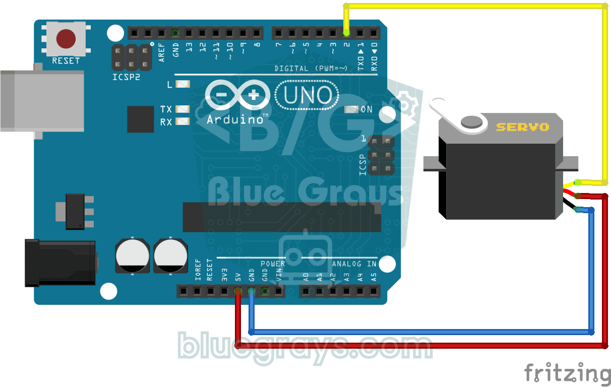
Using a Servo Motor
The arm of a small servo motor turns to three positions in turn: all the way to the start, right to the middle and all the way to the end, waiting two seconds at each stop. The Arduino tells the motor
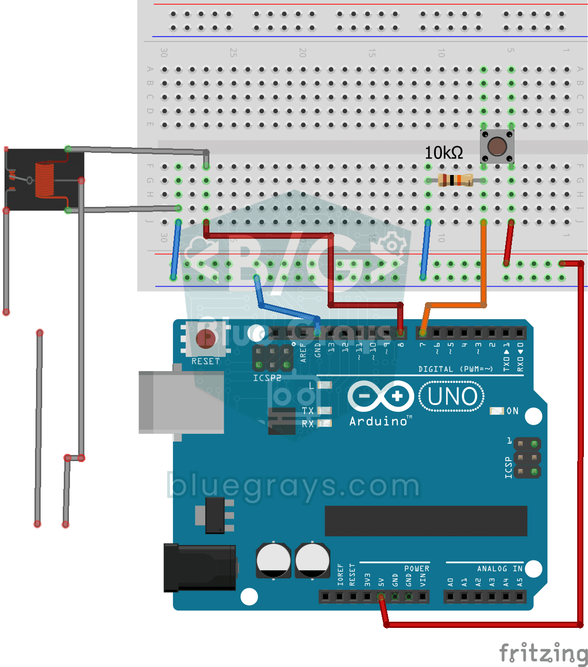
Lighting 220V Bulb with Push Button
As long as you hold the button, a real 220-volt bulb stays lit, and it goes out the moment you let go. The Arduino's tiny signal cannot light the bulb directly, so a relay, an electrically controlled

Bluetooth Controlled Car with L298N
Turn your phone into a remote and drive your own robot car. The Arduino receives commands from a remote-control app on your phone through a Bluetooth module and spins the wheels with a motor driver; t

Obstacle Avoidance Robot
How about building a smart vehicle that finds its own way? The Obstacle Avoidance Robot constantly scans its surroundings thanks to the ultrasonic sensor in front of it. When it encounters an obstacle

Smart Irrigation Station
A gardener that waters your plants on its own, so they don't dry out while you're on vacation. A soil moisture sensor measures how wet the soil is; when it gets dry, the Arduino runs the water pump fo

Servo Circle Choreography - Animated Patterns with 32 Servos
A visual animation project using 32 servo motors arranged in a circle on an Arduino Mega. The servos are managed in a single array, connected to Mega's pins 22-53, and exhibit four different motion sequences: a chaotic vibration where all servos move at random angles, a synchronous sweep where they all move at the same time, a smoothly rotating wave around a circle, and finally a compass needle swinging left and right. The swirling wave effect is created by the rotation of each servo relative to

ESP32 Servo Motor (Potentiometer Control)
In this project, we control an SG90 servo motor using a potentiometer. We adjust the servo angle by mapping the analog value read from the potentiometer to the 0–180-degree range. The ESP32Servo library generates servo signals on suitable output-capable GPIO pins of the ESP32; this project uses GPIO 18. This is a fundamental control method for robotic arms, camera gimbals, and automatic door mechanisms.