
4017 Running Light: 10 LEDs Stepped by a Button
Make the light jump to the next LED every time you press the button. The CD4017 decade counter counts the incoming clock pulses and lights only one of its ten outputs; after the tenth pulse it goes back to the start. A small resistor and capacitor filter cleans up the bounce of the button. You learn counter logic, the basis of running light effects and the clock pulse concept.
Video
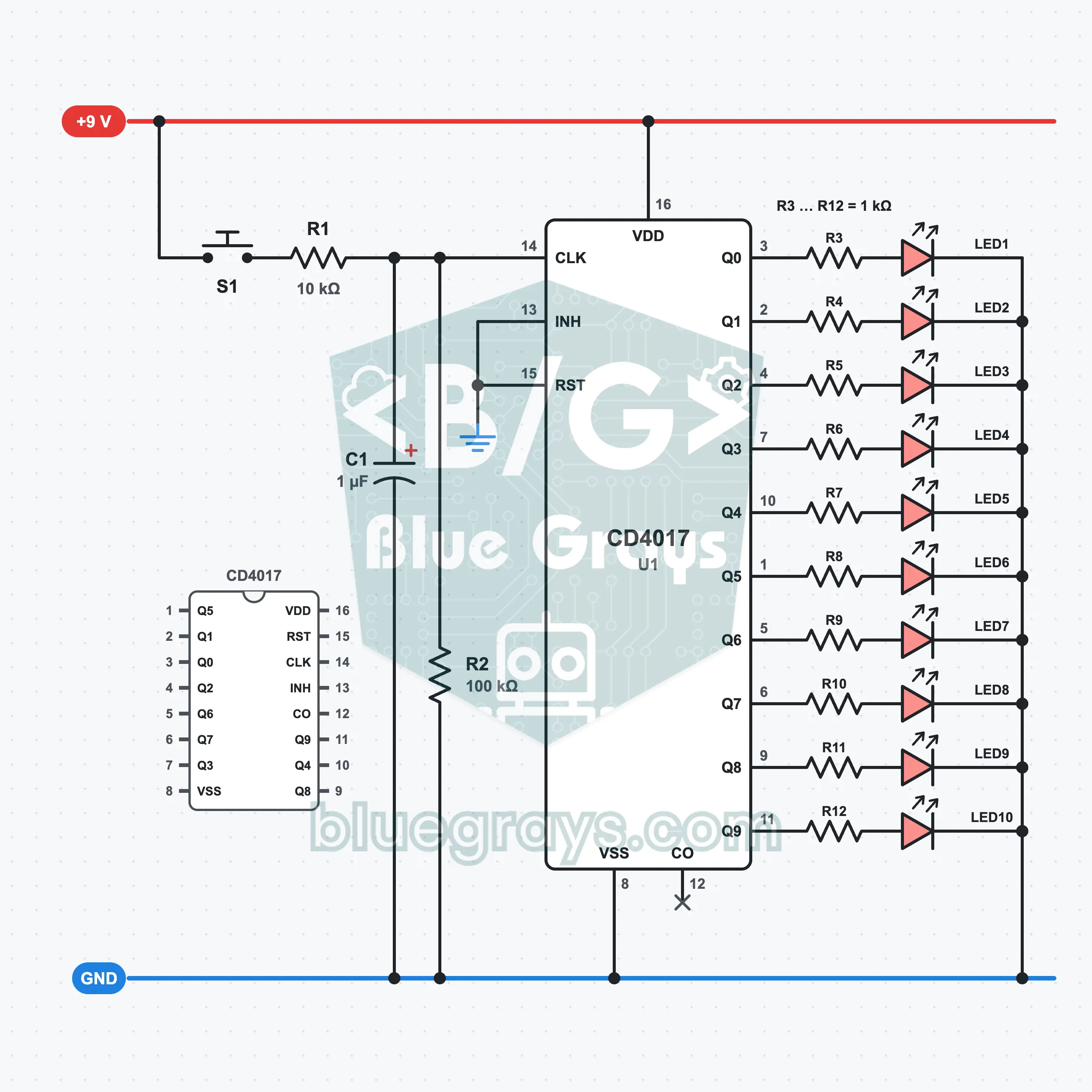
Circuit Diagram
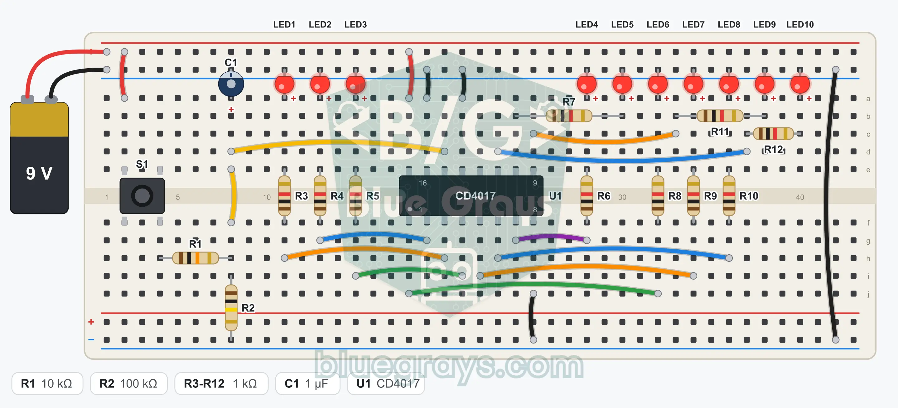
Breadboard Layout
Build Steps
- 1
Place the CD4017 (U1) over the center gap, on the left side of the breadboard, with its notch facing left. The bottom left corner is pin 1; the bottom row runs from 1 to 8 from left to right, and the top row runs from 9 to 16 from right to left.
- 2
Connect pin 16 to the + rail with a jumper wire and pin 8 to the GND (−) rail with a jumper wire.
- 3
Connect pin 13 and pin 15 to the GND rail with one jumper wire each. These are the clock inhibit and reset inputs.
- 4
Fit C1 (1 µF, electrolytic) between pin 14 and the GND rail: the long leg (+) goes to the pin 14 side, and the short leg next to the stripe on its body goes into the GND rail. An electrolytic capacitor fitted the wrong way round heats up and fails.
- 5
Fit R2 (100 kΩ) between pin 14 and the GND rail.
- 6
Place the S1 button over the center gap; connect the leg at one corner to the + rail with a jumper wire.
- 7
Fit R1 (10 kΩ): one end into the row of the leg at the diagonally opposite corner of S1, the other end into an empty row. Connect that empty row to pin 14 with a jumper wire.
- 8
Line up the ten LEDs side by side to the right of the IC, from LED1 to LED10 from left to right: the long leg (anode) of each LED into its own empty row, the short leg (cathode) into the GND rail. If the GND rail on this edge is not connected to the battery, connect it to the other GND rail with a jumper wire.
- 9
Fit the ten 1 kΩ resistors from R3 to R12: one end of each resistor goes into the anode row of an LED, the other end into the empty row on the opposite side of the center gap. From left to right, R3 is the resistor of LED1 and R12 that of LED10.
- 10
Connect pin 3 to the free end of R3 (LED1) with a jumper wire, and pin 2 to the free end of R4 (LED2).
- 11
Connect pin 4 to the free end of R5 (LED3), and pin 7 to the free end of R6 (LED4).
- 12
Connect pin 10 to the free end of R7 (LED5), and pin 1 to the free end of R8 (LED6).
- 13
Connect pin 5 to the free end of R9 (LED7), and pin 6 to the free end of R10 (LED8).
- 14
Connect pin 9 to the free end of R11 (LED9), and pin 11 to the free end of R12 (LED10). Pin 12 stays unconnected.
- 15
Plug the red wire of the battery clip into the + rail and the black wire into the GND rail. Compare the connections with the schematic and with the pinout, then snap the battery onto the clip.
Tip: keep the battery or power supply disconnected while wiring.
Test Steps
- 1
Connect the battery: only one of the LEDs must light. Which one lights at power-on is not predictable; if none of them light, press the button a few times.
- 2
Press S1 once: the light must move to the next LED on the right. The move happens the moment you press, not when you release the button.
- 3
Hold the button down: the light must stay where it is and must not move forward by itself.
- 4
Press the button ten times: the light returns to LED1 after LED10 and comes back to the LED it started from. It is normal for some presses to go uncounted if you press faster than 6 to 8 times a second.
- 5
Pull out the GND end of the jumper wire on pin 15 and touch it to the + rail for a moment: wherever the light is, it returns to LED1. Plug the jumper wire back into GND.
How It Works
On every pulse that arrives at its clock input, the CD4017 moves the lit LED one step forward, and after the tenth pulse it goes back to the start. S1 gives the pulse; R1, R2 and C1 filter out the switch bounce.
Decade counter
The CD4017 has ten outputs, Q0 to Q9, and only one of them is 1 at any moment. On every pulse that arrives at the clock input (pin 14), the output that is 1 shifts to the next one: it moves along Q0, Q1, Q2. After Q9 it returns to Q0 again. When you connect an LED to each output, the count shows up as a running light.
Clock pulse
The counter takes one step the moment the clock input rises from 0 to 1. When you are not pressing the button, R2 pulls the input to GND. When you press it, the input is connected to the + rail through R1 and rises. Releasing the button, that is, the fall from 1 to 0, does not change the count.
Debounce filter
The metal contacts of the button bounce for a few milliseconds as you press and produce dozens of pulses; with some buttons this lasts up to 10 ms. C1 swallows these fast pulses: when you press, it charges through R1 and pin 14 passes 4.5 V in about 7 ms. Even if the contact opens for a moment during a bounce, C1 can discharge only through R2, with a time constant of 100 ms, so the voltage hardly moves. When you release the button, the voltage falls below 4.5 V in about 60 ms. The clock input of the CD4017 has a Schmitt trigger: it counts even a slowly rising signal as one clean step.
Reset and clock inhibit
When pin 15 (reset) is set to 1, the counter returns to Q0 at once. When pin 13 (clock inhibit) is set to 1, the counter ignores the clock pulses and stops where it is. In this circuit both are connected to GND, so the counter counts freely.
LED resistors
Each output lights its own LED through a 1 kΩ resistor. The outputs of the CD4017 are not strong; the LEDs light with a few milliamps but are clearly visible. Because each LED has a separate resistor, both ends of the unlit LEDs are at 0 V and they are not under any voltage.
Formulas
Time constant of the filter on pressing
τ = (R1 × R2 / (R1 + R2)) × C1
Example: 9.1 kΩ × 1 µF ≈ 9.1 ms; the clock input passes 4.5 V in about 7 ms
Time constant of the filter on releasing
τ = R2 × C1
Example: 100 kΩ × 1 µF = 100 ms; the bounces are much shorter than this, so no second pulse occurs, and after you release the button the voltage falls below 4.5 V in about 60 ms
Voltage at the clock input while the button is pressed
V = Vcc × R2 / (R1 + R2)
Example: 9 V × 100 kΩ / 110 kΩ ≈ 8.2 V; more than enough to count as logic 1
LED current (upper limit)
I = (Vout − VLED) / R3
Example: (9 V − 2 V) / 1 kΩ = 7 mA; because the CD4017 output drops under load, the real current is around 5 mA
One full lap
1 lap = 10 clock pulses
Example: If you press the button 2 times a second, the light completes one lap in 10 / 2 = 5 seconds
Common Mistakes
The light jumps around out of order.
The output pins are not in order: 3, 2, 4, 7, 10, 1, 5, 6, 9, 11. Correct the jumper wires against the pinout.
It takes more than one step on a single press.
C1 is missing, has the wrong value or is not connected to pin 14. It must be 1 µF, with the long leg on the pin 14 side and the short, striped leg in the GND rail.
The light never moves forward.
Pin 13 and pin 15 must be at GND. If one of them is floating or in the + rail, the counter stops.
Some LEDs never light.
Those LEDs may be fitted backwards: the long leg must be on the resistor side and the short leg in the GND rail.
FAQ
Can I make the light run by itself, without the button?
Yes. It is enough to connect a circuit that produces regular pulses to the clock input in place of the button. If you connect the output of the 555 Flasher circuit (pin 3 of the 555) to pin 14 of the CD4017, the light runs by itself. Because both circuits work on 9 V, they can share the same battery; do not forget to join the GND rails.
Why does each LED have its own resistor? Isn't one resistor enough?
Because only one LED is lit at a time, the light runs with a shared resistor too. But with that connection the nine unlit LEDs sit under a reverse voltage of a few volts, and this can exceed the limit the LEDs allow. With separate resistors the cathode of each LED is directly at GND and no such problem occurs.
Why are the output pins not arranged in order?
The pin order was decided by the layout of the circuit inside the chip, not by ease of use. That is why Q0 is on pin 3, Q1 on pin 2 and Q5 on pin 1. When you work with integrated circuits you always have to look at the pinout; wiring from memory is the most common mistake.
What is pin 12 for?
Pin 12 is the carry output. It gives 1 in the first half of the count (0 to 4) and 0 in the second half (5 to 9); that is, it completes one full cycle every ten pulses. If it is connected to the clock input of a second CD4017, that IC counts the tens digit. Because it is not used in this circuit, it is left unconnected.