
Arduino Sensor Filtering: Moving Average, Median, EMA and Kalman
Arduino sensor filtering: moving average, median filter, EMA, hysteresis, sample rate, comparing filters in the Serial Plotter and a Kalman filter intro.
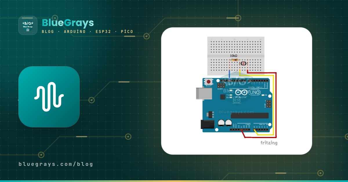
Arduino sensor filtering means turning the jittery, jumping values that come from analogRead() or a distance sensor into a calm, reliable number your project can use. Seeing 511, 513, 510, 514 in the Serial Monitor while you are not touching the potentiometer, an HC-SR04 that now and then reads 3 cm or 400 cm for no reason, a night light that flickers at the border between dark and light: these are all faces of the same problem. Most of the time the sensor is not broken; electrical noise, ADC step errors or the odd bad echo have crept into the reading. The good news: a filter of a few lines solves most of these problems.
In this guide you will first see the types of noise and the first measures to take on the circuit side. Then we will code five methods, starting with the simplest: multi-sample averaging, the moving average, the median filter that removes spikes, the exponential filter (EMA) that needs very little memory and hysteresis, which calms unstable thresholds. We will plot them side by side in the Arduino IDE's Serial Plotter, discuss how to choose the sample rate and give a short introduction to the Kalman filter. The last sections cover the ESP32's noisy ADC and MicroPython code for the Raspberry Pi Pico.
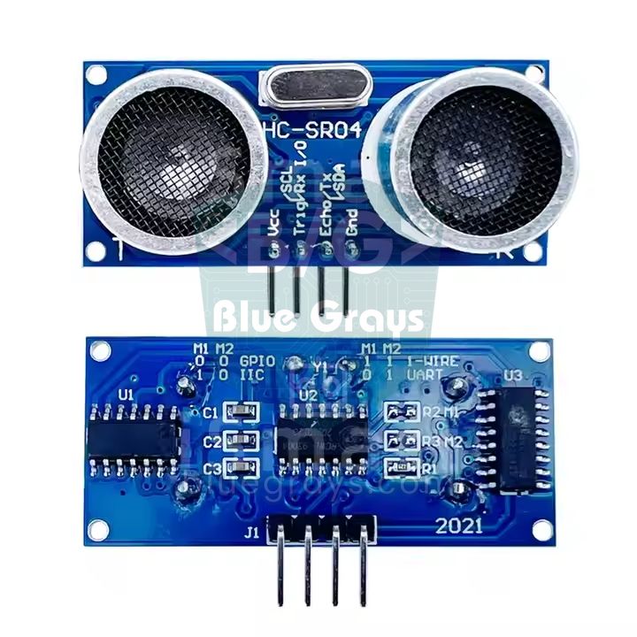
Why is sensor data noisy?
It is misleading to think of measurement error as one single thing. Different kinds of noise need different filters, so first you need to know which problem you have. Printing raw values to the Serial Monitor for a while and looking at the numbers is enough for that. If the values keep jittering around a certain number, you have random noise; if most readings are right but now and then a completely absurd value arrives, you have spikes; if the value slowly creeps, the problem is not noise but drift.
| Noise type | What it looks like | Typical cause | Suitable fix |
|---|---|---|---|
| Random noise | The value jitters by ±2–10 counts | Supply ripple, long wires, the ADC's own noise | Averaging, moving average, EMA |
| Spike | An occasional value that is far off | Missed echo on the HC-SR04, loose contact, motor interference | Median filter |
| Step (quantization) error | The value flips between two neighbouring numbers | ADC resolution (5 V / 1024 = 4.9 mV on the Uno) | Averaging, hysteresis |
| Periodic noise | Regular ripple | 100 Hz flicker of lamps, 50 Hz mains | Averaging over multiples of 20 ms |
| Drift | The value changes slowly over minutes | Temperature, falling battery voltage | Calibration and a stable reference, not a filter |
Circuit first: reduce noise at the source
A software filter cannot bring back information the circuit never captured, so the first job is to make it harder for noise to get in. Keep analog sensor wires short and route them away from the wires of current-hungry parts such as motors and relays. A 100 nF ceramic capacitor between the analog input and GND, placed close to the sensor, absorbs much of the fast interference. The cut-off frequency of an RC low-pass filter made of a resistor and a capacitor is given by f = 1 / (2πRC): 10 kΩ and 1 µF give about 16 Hz, so faster changes are suppressed. You can calculate the values with the RC time constant tool. In motor projects it also helps to bring the sensors' GND to the board along a separate path from the motor driver's GND and to power the board from a stable supply. We explain how the ADC works and how the reference voltage affects it in What is an ADC?.
Test setup
We will try the code in this article with three easy sensors. The potentiometer is ideal for seeing random noise, the LDR for periodic noise and threshold decisions, and the HC-SR04 for spikes. Connect the LDR between 5 V and the analog pin and the 10 kΩ resistor between the analog pin and GND, so that the reading rises as the light gets brighter. For details see the LDR light sensor and potentiometer articles.
| Connection | Arduino Uno | ESP32 | Raspberry Pi Pico |
|---|---|---|---|
| Potentiometer wiper | A0 | GPIO 34 | GP26 (ADC0) |
| LDR + 10 kΩ divider midpoint | A1 | GPIO 35 | GP27 (ADC1) |
| HC-SR04 TRIG | D9 | GPIO 5 | GP2 |
| HC-SR04 ECHO | D10 | GPIO 18 (with divider) | GP3 (with divider) |
| LED or relay (hysteresis example) | D8 | - | - |
| Supply | Pot and LDR 5V, HC-SR04 5V | Pot and LDR 3V3, HC-SR04 5V | Pot and LDR 3V3, HC-SR04 VBUS |
1. Multi-sample averaging
The simplest filter is to take several readings in a row and use their average. Random noise pushes each reading in a different direction, so it cancels out in the sum. Statistics has a rule for this: in the average of N independent readings, the noise drops by about √N. 4 samples halve the noise and 16 samples cut it to a quarter; 64 samples cut it to an eighth but take four times longer. On the Arduino Uno a single analogRead() takes about 112 µs, so a 16-sample average is done in under 2 ms. The only drawbacks of this method are that it keeps the processor busy briefly for every reading and that it is weak against spikes: if one of the 16 samples is absurd, it spoils the average too.
1const int POT_PIN = A0;
2
3// Art arda "adet" ölçüm al, ortalamasını döndür / take "adet" readings in a row, return the average
4int ortalamaOku(int pin, int adet) {
5  long toplam = 0;                  // taşmasın diye long / long to avoid overflow
6  for (int i = 0; i < adet; i++) {
7    toplam += analogRead(pin);
8    delayMicroseconds(100);         // ölçümler arasında kısa ara / short gap between readings
9  }
10  return toplam / adet;
11}
12
13void setup() {
14  Serial.begin(115200);
15}
16
17void loop() {
18  int ham = analogRead(POT_PIN);
19  int ort4 = ortalamaOku(POT_PIN, 4);
20  int ort16 = ortalamaOku(POT_PIN, 16);
21  // Serial Plotter için etiket:değer biçimi / label:value format for the Serial Plotter
22  Serial.print("Ham:");
23  Serial.print(ham);
24  Serial.print(",Ort4:");
25  Serial.print(ort4);
26  Serial.print(",Ort16:");
27  Serial.println(ort16);
28  delay(20);
29}
2. Moving average
A moving average keeps the average of the last N readings and, with every new reading, drops the oldest and adds the new one. That way you take one reading per loop but still benefit from an N-reading average. Instead of adding up N numbers every time, the code keeps a sum variable: it subtracts the value leaving and adds the value entering. So the calculation runs at the same speed no matter how large the window is. The price of a moving average is delay: the output lags the real value by about (N−1)/2 readings. A 10-reading window sampled every 10 ms lags by about 45 ms; that does not matter for a potentiometer or temperature, but you can feel it in a fast robot.
1const int POT_PIN = A0;
2const int PENCERE = 10;            // son 10 ölçüm / last 10 readings
3
4int tampon[PENCERE];               // dairesel tampon / circular buffer
5int sira = 0;
6long toplam = 0;
7bool dolu = false;
8
9int hareketliOrtalama(int yeni) {
10  toplam -= tampon[sira];          // en eski değeri çıkar / remove the oldest value
11  tampon[sira] = yeni;
12  toplam += yeni;                  // yeni değeri ekle / add the new value
13  sira = (sira + 1) % PENCERE;
14  if (sira == 0) dolu = true;
15  return dolu ? toplam / PENCERE : toplam / sira;   // ilk turda bölen küçük / smaller divisor at start
16}
17
18unsigned long sonOlcum = 0;
19
20void setup() {
21  Serial.begin(115200);
22}
23
24void loop() {
25  if (millis() - sonOlcum >= 10) { // 100 Hz örnekleme / 100 Hz sampling
26    sonOlcum = millis();
27    int ham = analogRead(POT_PIN);
28    int filtreli = hareketliOrtalama(ham);
29    Serial.print("Ham:");
30    Serial.print(ham);
31    Serial.print(",Hareketli:");
32    Serial.println(filtreli);
33  }
34}| Window (N) | Noise reduction | Delay (one reading every 10 ms) | Good for |
|---|---|---|---|
| 4 | About 2× | 15 ms | Control that needs a fast response |
| 10 | About 3× | 45 ms | Potentiometer, joystick, LDR |
| 32 | About 5.7× | 155 ms | Temperature, humidity, battery voltage |
| 100 | 10× | 495 ms | Very slowly changing values, calm display output |
3. Median filter: removing spikes
Averaging is weak against spikes. If the HC-SR04 reads 50 cm four times and then misses the echo once and reads 0, the average of the five is 40 cm; that value is neither correct nor does it show the error. A median filter instead sorts the last N readings from smallest to largest and takes the middle one. In the same example the sorted list is 0, 50, 50, 50, 50 and the middle value is 50; the bad reading never reaches the result. A 5-element median filter completely removes up to 2 bad readings in a row. The second nice property of the median is that it does not smear a sudden, real change the way an average does: when an obstacle really gets closer, the value jumps to the new level in a clean step within a few readings instead of a soft curve. The code below takes an HC-SR04 reading every 60 ms and prints the median of the last 5. For details see the HC-SR04 distance sensor article.
1const int TRIG_PIN = 9;
2const int ECHO_PIN = 10;
3const int N = 5;                   // medyan penceresi, tek sayı olmalı / median window, must be odd
4
5int olcumler[N];
6int sira = 0;
7
8int mesafeOlc() {
9  digitalWrite(TRIG_PIN, LOW);
10  delayMicroseconds(2);
11  digitalWrite(TRIG_PIN, HIGH);
12  delayMicroseconds(10);
13  digitalWrite(TRIG_PIN, LOW);
14  unsigned long sure = pulseIn(ECHO_PIN, HIGH, 25000);   // ~4 m zaman aşımı / ~4 m timeout
15  return sure / 58;                                       // yankı yoksa 0 / 0 if no echo
16}
17
18int medyan() {
19  int kopya[N];
20  for (int i = 0; i < N; i++) kopya[i] = olcumler[i];
21  for (int i = 1; i < N; i++) {    // eklemeli sıralama / insertion sort
22    int deger = kopya[i];
23    int j = i - 1;
24    while (j >= 0 && kopya[j] > deger) {
25      kopya[j + 1] = kopya[j];
26      j--;
27    }
28    kopya[j + 1] = deger;
29  }
30  return kopya[N / 2];             // ortadaki eleman / middle element
31}
32
33void setup() {
34  Serial.begin(115200);
35  pinMode(TRIG_PIN, OUTPUT);
36  pinMode(ECHO_PIN, INPUT);
37  for (int i = 0; i < N; i++) {    // tamponu ilk ölçümlerle doldur / fill the buffer first
38    olcumler[i] = mesafeOlc();
39    delay(60);
40  }
41}
42
43void loop() {
44  int ham = mesafeOlc();
45  olcumler[sira] = ham;
46  sira = (sira + 1) % N;
47  Serial.print("Ham:");
48  Serial.print(ham);
49  Serial.print(",Medyan:");
50  Serial.println(medyan());
51  delay(60);                       // HC-SR04 için en az 60 ms / at least 60 ms for HC-SR04
52}4. Exponential filter (EMA): smoothing with little memory
The exponential moving average (EMA) uses no buffer; it only remembers the previous result. With each new reading the result moves towards the reading by a small fraction of the difference between them: y = y + α × (x − y). Here x is the new reading, y the filtered value and α (alpha) a coefficient between 0 and 1. The smaller α is, the calmer but slower the filter becomes. It is called exponential because the influence of each reading fades exponentially over time. It is the software counterpart of the RC low-pass filter in electronics. The EMA's time constant is roughly τ ≈ T / α (T is the sample interval): with a reading every 10 ms and α = 0.1, the filter reaches 63 percent of a sudden change in about 100 ms and 95 percent in about 300 ms. The code has both a floating-point version and an integer version that runs faster on small boards like the Uno; the integer version uses α = 1/16 and a shift (>>) instead of a division.
1const int LDR_PIN = A1;
2const float ALFA = 0.1;            // 0-1 arası; küçük = daha sakin / 0-1; smaller = smoother
3
4float ema = -1;                    // henüz başlamadı / not started yet
5long emaX16 = -1;                  // tamsayılı EMA x16 / integer EMA times 16
6
7unsigned long sonOlcum = 0;
8
9void setup() {
10  Serial.begin(115200);
11}
12
13void loop() {
14  if (millis() - sonOlcum >= 10) {
15    sonOlcum = millis();
16    int ham = analogRead(LDR_PIN);
17
18    if (ema < 0) ema = ham;        // ilk değerle başlat / start from the first reading
19    ema += ALFA * (ham - ema);     // y = y + a(x - y)
20
21    if (emaX16 < 0) emaX16 = (long)ham << 4;
22    emaX16 += ham - (emaX16 >> 4); // alfa = 1/16, float yok / alpha = 1/16, no float
23
24    Serial.print("Ham:");
25    Serial.print(ham);
26    Serial.print(",EMA:");
27    Serial.print(ema, 1);
28    Serial.print(",EMA_int:");
29    Serial.println(emaX16 >> 4);
30  }
31}| α (alpha) | Approximate equivalent window | 63% response time (10 ms sampling) | Character |
|---|---|---|---|
| 0.5 | 3 | 10–20 ms | Very fast, little smoothing |
| 0.2 | 9 | 50 ms | Fast, light smoothing |
| 0.1 | 19 | 100 ms | Balanced, a good starting point for most sensors |
| 0.05 | 39 | 200 ms | Calm, slow |
| 0.01 | 199 | 1 s | Very calm, only for slowly changing values |
The "equivalent window" in the table is the approximate size of a moving average that gives the same smoothing and is calculated as N ≈ 2/α − 1. The EMA's biggest advantage is memory: a 100-element moving average needs 200 bytes of RAM, while the EMA needs a single variable. If you need to filter several sensors in the Arduino Uno's 2 KB of RAM, that difference matters. Its drawback is that it is as weak against spikes as averaging; a large spike pulls the result for several readings.
Comparing filters in the Serial Plotter
The difference between filters is hard to see in numbers but obvious at a glance on a graph. The code below reads the potentiometer at 100 Hz, passes the same reading through four different paths and prints them all in label:value format. To make the difference clearer, the code adds an artificial spike to about 3 percent of the readings; remove this line in a real project. On the graph you will see that the median removes the spikes completely, while the moving average and EMA turn them into small bumps.
- Upload the code and close the Serial Monitor if it is open; the Serial Monitor and Serial Plotter cannot be open at the same time.
- In the Arduino IDE open Tools > Serial Plotter or click the graph icon at the top right.
- Set the speed at the bottom right to 115200 baud.
- Turn the potentiometer slowly and then quickly, and watch how each line responds.
- Use the boxes next to the labels to switch lines on and off and compare two filters directly.
1const int POT_PIN = A0;
2
3// Hareketli ortalama / moving average
4const int PENCERE = 10;
5int maTampon[PENCERE];
6int maSira = 0;
7long maToplam = 0;
8
9int hareketliOrtalama(int yeni) {
10  maToplam += yeni - maTampon[maSira];
11  maTampon[maSira] = yeni;
12  maSira = (maSira + 1) % PENCERE;
13  return maToplam / PENCERE;
14}
15
16// 5'lik medyan / median of 5
17int mdTampon[5];
18int mdSira = 0;
19
20int medyan5(int yeni) {
21  mdTampon[mdSira] = yeni;
22  mdSira = (mdSira + 1) % 5;
23  int a[5];
24  for (int i = 0; i < 5; i++) a[i] = mdTampon[i];
25  for (int i = 1; i < 5; i++) {    // eklemeli sıralama / insertion sort
26    int d = a[i], j = i - 1;
27    while (j >= 0 && a[j] > d) { a[j + 1] = a[j]; j--; }
28    a[j + 1] = d;
29  }
30  return a[2];
31}
32
33// Üstel filtre / exponential filter
34float ema = 0;
35const float ALFA = 0.1;
36
37unsigned long sonOlcum = 0;
38
39void setup() {
40  Serial.begin(115200);
41  int ilk = analogRead(POT_PIN);
42  for (int i = 0; i < PENCERE; i++) maTampon[i] = ilk;   // tamponları doldur / prefill buffers
43  maToplam = (long)ilk * PENCERE;
44  for (int i = 0; i < 5; i++) mdTampon[i] = ilk;
45  ema = ilk;
46  randomSeed(analogRead(A5));
47}
48
49void loop() {
50  if (millis() - sonOlcum < 10) return;   // 100 Hz
51  sonOlcum = millis();
52
53  int ham = analogRead(POT_PIN);
54  if (random(100) < 3) {                  // TEST: %3 yapay sıçrama, projede sil / TEST: 3% fake spikes, remove in a project
55    ham = constrain(ham + random(-400, 400), 0, 1023);
56  }
57  ema += ALFA * (ham - ema);
58
59  Serial.print("Ham:");
60  Serial.print(ham);
61  Serial.print(",Hareketli:");
62  Serial.print(hareketliOrtalama(ham));
63  Serial.print(",Medyan:");
64  Serial.print(medyan5(ham));
65  Serial.print(",EMA:");
66  Serial.println(ema, 1);
67}
On the graph the labels appear in colour at the top right. If you do not use a comma between labels and a colon between label and value, the Serial Plotter cannot separate the lines correctly. The old plotter in Arduino IDE 1.8 has limited label support; if you run into trouble, send only comma-separated numbers. For serial port and baud rate problems, have a look at the Arduino Serial Monitor article.
5. Hysteresis: stopping decisions that flicker at the threshold
A filter calms the value, but on its own it does not solve the decision problem. A night light that says "turn the lamp on when the light value drops below 350" switches on and off several times a second at dusk as the value wanders between 349 and 351. That quickly wears out a relay's contacts. The solution is hysteresis: two separate thresholds are used for switching on and switching off. For example, the lamp turns on when the value drops below 300, but it has to rise above 400 to turn off. The 100-count "dead band" in between stops small fluctuations from changing the decision. The code below combines hysteresis with an EMA and a short confirmation time: the condition must hold without interruption for 1 second, so a passing shadow or a moment of headlights does not change the decision either.
1const int LDR_PIN = A1;
2const int LAMBA_PIN = 8;           // LED ya da röle modülü / LED or relay module
3const int YAK_ESIK = 300;          // bunun altı karanlık / below this is dark
4const int SONDUR_ESIK = 400;       // bunun üstü aydınlık / above this is bright
5const unsigned long ONAY_MS = 1000;   // koşul 1 sn sürmeli / condition must last 1 s
6
7float ema = -1;
8bool lambaAcik = false;
9unsigned long kosulBasladi = 0;
10bool kosulVar = false;
11
12void setup() {
13  Serial.begin(115200);
14  pinMode(LAMBA_PIN, OUTPUT);
15}
16
17void loop() {
18  int ham = analogRead(LDR_PIN);
19  if (ema < 0) ema = ham;
20  ema += 0.05 * (ham - ema);       // yavaş EMA / slow EMA
21
22  // Durum değiştirmek için hangi koşul gerekiyor? / which condition flips the state?
23  bool degistir = lambaAcik ? (ema > SONDUR_ESIK) : (ema < YAK_ESIK);
24
25  if (degistir) {
26    if (!kosulVar) {
27      kosulVar = true;
28      kosulBasladi = millis();     // koşul şimdi başladı / condition just started
29    } else if (millis() - kosulBasladi >= ONAY_MS) {
30      lambaAcik = !lambaAcik;      // 1 sn sürdü, kararı değiştir / lasted 1 s, flip the decision
31      digitalWrite(LAMBA_PIN, lambaAcik ? HIGH : LOW);
32      kosulVar = false;
33    }
34  } else {
35    kosulVar = false;              // koşul bozuldu, sayacı sıfırla / condition broke, reset the timer
36  }
37
38  Serial.print("EMA:");
39  Serial.print(ema, 0);
40  Serial.print(",Yak:");
41  Serial.print(YAK_ESIK);
42  Serial.print(",Sondur:");
43  Serial.print(SONDUR_ESIK);
44  Serial.print(",Lamba:");
45  Serial.println(lambaAcik ? 600 : 100);   // grafikte görünsün / visible on the plot
46  delay(10);
47}
Before setting the thresholds, watch the room's values over the day in the Serial Plotter. The dead band should be at least two to three times wider than the jitter of the filtered value. The same method is used in thermostats (for example, turn the heater off at 22 °C and on at 20 °C), in water tank pumps and in battery protection circuits. Button debouncing is really a kind of confirmation time too; the details are in How to wire a button.
How to choose the sample rate
For a filter to work well, the sensor has to be read at the right rate. Read too slowly and you miss fast changes; read too fast and the sensor returns the same value again and again or is not ready at all. The basic rule is the Nyquist rule: sample at least twice as fast as the fastest change you want to follow; in practice 5–10 times is safer. Some sensors also have their own lower limit, and reading them faster brings no benefit. If light flicker matters, note that on a 50 Hz grid lamps flicker 100 times a second. The easiest way to cancel this flicker on an LDR or another analog sensor is to take evenly spaced readings over a period that is a multiple of 20 ms and average them; because the window covers whole mains periods, the flicker cancels itself out.
| Sensor | Recommended read interval | Note |
|---|---|---|
| DHT11 / DHT22 | 1 s / 2 s | Reading more often returns the same value or an error |
| DS18B20 (12-bit) | 750 ms | That is the conversion time |
| HC-SR04 | At least 60 ms | Wait for the previous echo to die away |
| Potentiometer, joystick | 10–20 ms | 50–100 Hz is more than enough for human movement |
| LDR (to suppress lamp flicker) | Every 1 ms for 20 ms, then average | The 50 Hz mains flicker cancels out |
| MPU6050 | 5–10 ms | A common range for 100–200 Hz motion measurement |
A short introduction to the Kalman filter
The Kalman filter takes into account how noisy the measurement is and how fast the real value can change, and adjusts its own gain. In its simplest one-dimensional form it has two settings: R is the variance of the measurement noise (how much the sensor jitters); Q is the process noise (how fast you expect the real value to change). At each step the filter first increases its uncertainty by Q, then calculates the gain K = P / (P + R) and moves its estimate towards the measurement by the fraction K. If the measurement is noisy (large R), K is small and the filter trusts the measurement less; if the value is expected to change quickly (large Q), K grows and the filter reacts fast. A striking result: when Q and R are fixed, K settles to a constant after a while and the one-dimensional Kalman filter effectively becomes an EMA. Kalman's real power shows when it estimates several quantities together, for example combining accelerometer and gyroscope data to find a tilt angle. You will find its simpler cousin, the complementary filter, in the MPU6050 article.
1const int POT_PIN = A0;
2
3struct Kalman1D {
4  float q;      // süreç gürültüsü / process noise
5  float r;      // ölçüm gürültüsü (varyans) / measurement noise (variance)
6  float p;      // tahminin belirsizliği / estimate uncertainty
7  float x;      // tahmin / estimate
8  bool ilk;
9};
10
11Kalman1D kf = {0.05, 9.0, 1.0, 0.0, true};   // r = 9: yaklaşık ±3 basamak titreşim / about ±3 counts of jitter
12
13float kalmanGuncelle(Kalman1D &k, float olcum) {
14  if (k.ilk) { k.x = olcum; k.ilk = false; return k.x; }
15  k.p += k.q;                          // 1. tahmin: belirsizlik artar / predict: uncertainty grows
16  float kazanc = k.p / (k.p + k.r);    // 2. Kalman kazancı / Kalman gain
17  k.x += kazanc * (olcum - k.x);       // 3. ölçüme doğru düzelt / correct toward the measurement
18  k.p *= (1.0 - kazanc);               // 4. belirsizlik azalır / uncertainty shrinks
19  return k.x;
20}
21
22void setup() {
23  Serial.begin(115200);
24}
25
26void loop() {
27  int ham = analogRead(POT_PIN);
28  float tahmin = kalmanGuncelle(kf, ham);
29  Serial.print("Ham:");
30  Serial.print(ham);
31  Serial.print(",Kalman:");
32  Serial.println(tahmin, 1);
33  delay(10);
34}
R is easy to estimate: take 100 raw readings without touching the potentiometer and look at how widely the values are scattered. If they wander about ±3 counts around the average, the standard deviation is about 3 and the variance about 9. Find Q by experiment: a small Q (0.001) gives a very calm but slow output, a large Q (1) a fast but more jittery one. As a starting point, choose Q between 1 and 10 percent of R and fine-tune it in the Serial Plotter while turning the potentiometer.
ADC noise and filtering on the ESP32
The ESP32's 12-bit ADC resolves finer steps than the Arduino Uno's, but it is noisier and not linear, especially at the 0–0.1 V and 3.1–3.3 V ends. With Wi-Fi on, the noise increases further. Two things make life easier: use analogReadMilliVolts(), which applies the chip's factory calibration instead of returning a raw value, and average 16–64 samples per reading before applying an EMA. The code below reads the potentiometer in these two steps; in projects that use Wi-Fi, always connect the sensor to the ADC1 pins GPIO 32–39.
1const int POT_PIN = 34;            // ADC1 pini, Wi-Fi ile çalışır / ADC1 pin, works with Wi-Fi
2const int ORNEK = 32;              // her ölçümde 32 örnek / 32 samples per reading
3const float ALFA = 0.15;
4
5float ema = -1;
6
7int millivoltOku() {
8  uint32_t toplam = 0;
9  for (int i = 0; i < ORNEK; i++) {
10    toplam += analogReadMilliVolts(POT_PIN);   // kalibre mV / calibrated mV
11  }
12  return toplam / ORNEK;
13}
14
15void setup() {
16  Serial.begin(115200);
17  analogReadResolution(12);        // 0-4095
18}
19
20void loop() {
21  int ham = analogRead(POT_PIN);   // karşılaştırma için tek ham ölçüm / single raw reading for comparison
22  int mv = millivoltOku();
23  if (ema < 0) ema = mv;
24  ema += ALFA * (mv - ema);
25  Serial.printf("Ham:%d,mV:%d,EMA_mV:%.1f\n", ham, mv, ema);
26  delay(20);
27}
Filtering with the Raspberry Pi Pico and MicroPython
On the Raspberry Pi Pico ADC.read_u16() returns a value between 0 and 65535, but the ADC's real resolution is 12 bits and the lower bits are noisy. In MicroPython the sorted() function makes the median very easy, and a list plus a running sum is enough for a moving average. The code below reads the potentiometer at 100 Hz and prints the output of three filters in a format Thonny can draw in its View > Plotter window.
1from machine import ADC
2import time
3
4pot = ADC(26)                     # GP26 = ADC0
5
6PENCERE = 10
7tampon = [pot.read_u16()] * PENCERE   # hareketli ortalama tamponu / moving average buffer
8toplam = sum(tampon)
9sira = 0
10son5 = tampon[:5]                 # medyan için son 5 değer / last 5 values for the median
11ema = float(tampon[0])
12ALFA = 0.1
13
14while True:
15    ham = pot.read_u16()
16
17    toplam += ham - tampon[sira]  # hareketli ortalama / moving average
18    tampon[sira] = ham
19    sira = (sira + 1) % PENCERE
20    hareketli = toplam // PENCERE
21
22    son5.pop(0)                   # medyan / median
23    son5.append(ham)
24    medyan = sorted(son5)[2]
25
26    ema += ALFA * (ham - ema)     # üstel filtre / exponential filter
27
28    print("Ham:", ham, "Hareketli:", hareketli, "Medyan:", medyan, "EMA:", int(ema))
29    time.sleep_ms(10)
Thonny's plotter shows the numbers on each line as separate lines and uses the text in front of the numbers as labels. MicroPython runs slower than Arduino, so do not push the filters to very high rates; around 100 Hz with small windows runs comfortably on the Pico. If you are new to MicroPython, start with the MicroPython basics article.
Which filter should you choose?
| Situation | Suggested filter | Why? |
|---|---|---|
| A potentiometer, joystick or analog sensor jitters | Moving average or EMA (α = 0.1–0.2) | Simple, fast, enough smoothing |
| An absurd value arrives now and then (HC-SR04, flow sensor) | 3- or 5-point median | Removes the odd error completely |
| Both spikes and jitter | Median first, then EMA | Solves the two problems in turn |
| Very little RAM, many sensors | Integer EMA | One variable per sensor |
| An on/off decision flickers at the threshold | Hysteresis and a confirmation time | Solves the decision problem; a filter alone is not enough |
| Ripple from lamps or the mains | Evenly spaced average over 20 ms | Covers a whole 50 Hz period |
| Combining several sensors (tilt, position) | Kalman or complementary filter | Combines the strengths of each sensor |
Common mistakes and fixes
| Symptom | Likely cause | Fix |
|---|---|---|
| The filtered value responds far too late | The window is too large or α too small | Shrink the window or raise α; work out the delay from the tables |
| The moving average climbs slowly from zero at start-up | The buffer starts filled with zeros | Prefill the buffer with the first reading, or divide by the count until it is full |
| The average goes haywire at 64 samples | The int sum overflowed (64 × 1023 = 65,472 > 32,767) | Make the sum variable a long |
| The median filter changes nothing | The window is 2 or an even number, or the spikes arrive in a row | Use an odd window (3, 5, 7) larger than the number of spikes in a row |
| Serial Plotter lines are merged or all one colour | Wrong label format | Use label:value with commas in between and end the line with println |
| The EMA value never changes | Integer division: 1/10 written instead of 0.1 | Write the coefficient as a float (0.1) or use the integer EMA formula |
| Values still fluctuate despite the filter | The problem is not noise but drift or a weak supply | Check the supply, add a 100 nF capacitor and calibrate |
Sensor filtering is the cheapest way to make measurements reliable: it needs no extra parts, and a few lines of code make your projects run more steadily. Now that you know how to use averaging, the moving average, the median, the EMA and hysteresis together, jittery displays, false alarms and chattering relays are behind you. In the BlueGrays app you can explore projects such as measuring light with an LDR, a night light, measuring distance with the HC-SR04, a parking sensor and a height meter, with step-by-step circuit diagrams and ready-to-use code, and see the results for yourself by adding these filters to them.
Frequently asked questions
Why do sensor values on Arduino keep changing?
In analog readings, supply ripple, long wires, nearby motors and the ADC's own noise move the value by a few counts. This is normal and does not mean the sensor is broken. Adding a 100 nF capacitor to the analog input and using an averaging or EMA filter in software calms the values down.
What is a moving average?
A moving average is the average of the last N readings; with every new reading the oldest value is removed and the new one added. It reduces noise by about √N but delays the output by (N−1)/2 readings. On Arduino it takes only a few lines with a circular buffer and a single sum variable.
What is the difference between a median filter and an average?
An average takes every value into account, so a single absurd reading spoils the result. A median filter sorts the values and takes the middle one, so it ignores occasional bad readings completely. That is why the median is better for sensors like the HC-SR04 that sometimes give wrong values, and averaging is better for jittery analog readings.
How do I choose the coefficient for an exponential filter (EMA)?
The coefficient α lies between 0 and 1; a small α gives a calmer but slower output, a large α a faster but more jittery one. With a reading every 10 ms, α = 0.1 gives a time constant of about 100 ms and is a good starting point for most sensors. You can work out the response time with τ ≈ T / α.
How do I plot several values in the Arduino Serial Plotter?
Print the values on each line in label:value format with commas between them and end the line with println, for example Ham:512,EMA:509. The Serial Plotter shows each label as a separate coloured line. Close the Serial Monitor first if it is open and set the baud rate to match your code.
Can a Kalman filter be used on Arduino?
Yes, a simple one-dimensional Kalman filter runs in a few lines even on an Arduino Uno. It is tuned with the measurement noise R and the process noise Q; for a single sensor its results are usually very close to a well-tuned EMA. Its real benefit appears when combining several sensors, such as an accelerometer and a gyroscope.
Projects to build after reading this
See all projects
Measuring Light Intensity with an LDR
Want to see how bright your room is as a number? The LDR, a small part that reacts to light, measures the light around it, and the Arduino writes the value to your computer screen every half second. C
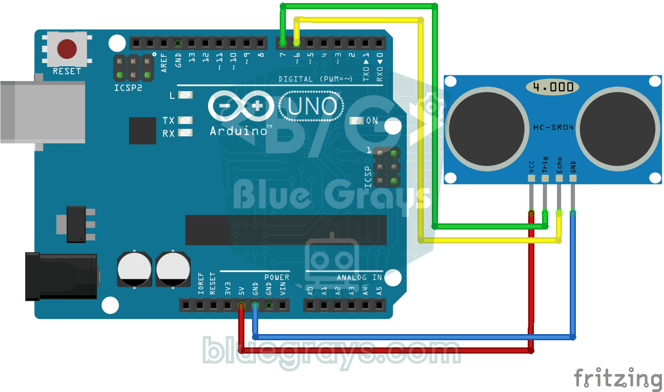
HC-SR04 Distance Measurement (Serial Display)
The HC-SR04 sensor works just like a bat finding its way in the dark: it sends out a sound you cannot hear, listens for the echo and measures how far away the object in front of it is. The Arduino wri

Night Light with Ldr
A little night light that turns on by itself when it gets dark and goes off when morning comes. A light sensor measures how bright the room is, and the Arduino switches the LED on when it is dark enou
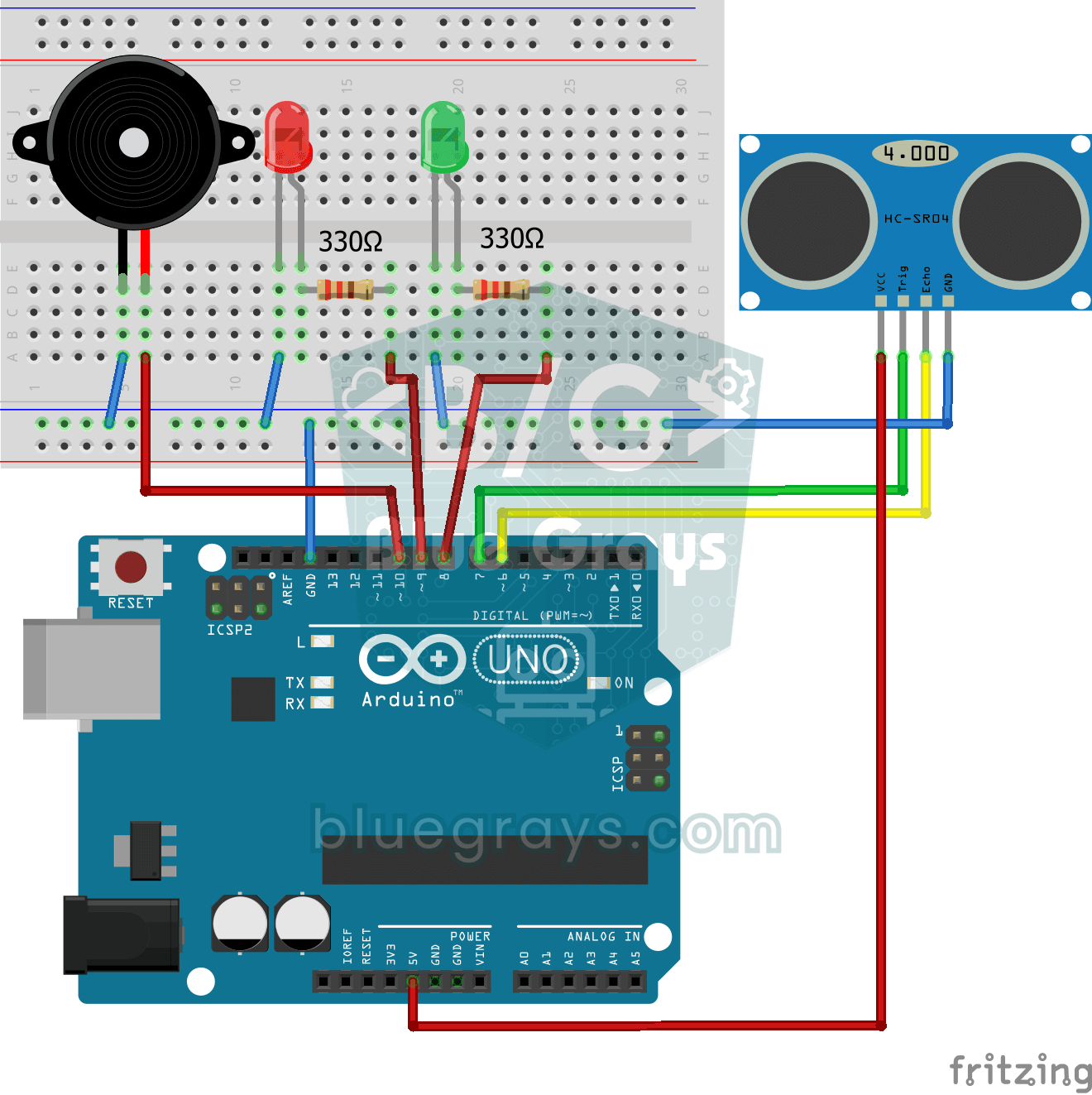
Parking Sensor with HC-SR04
A mini version of a car's parking sensor: the closer something gets, the faster the beeps. The distance sensor measures the object in front of it; if it is more than 20 centimetres away the green LED
Height Measurement Project
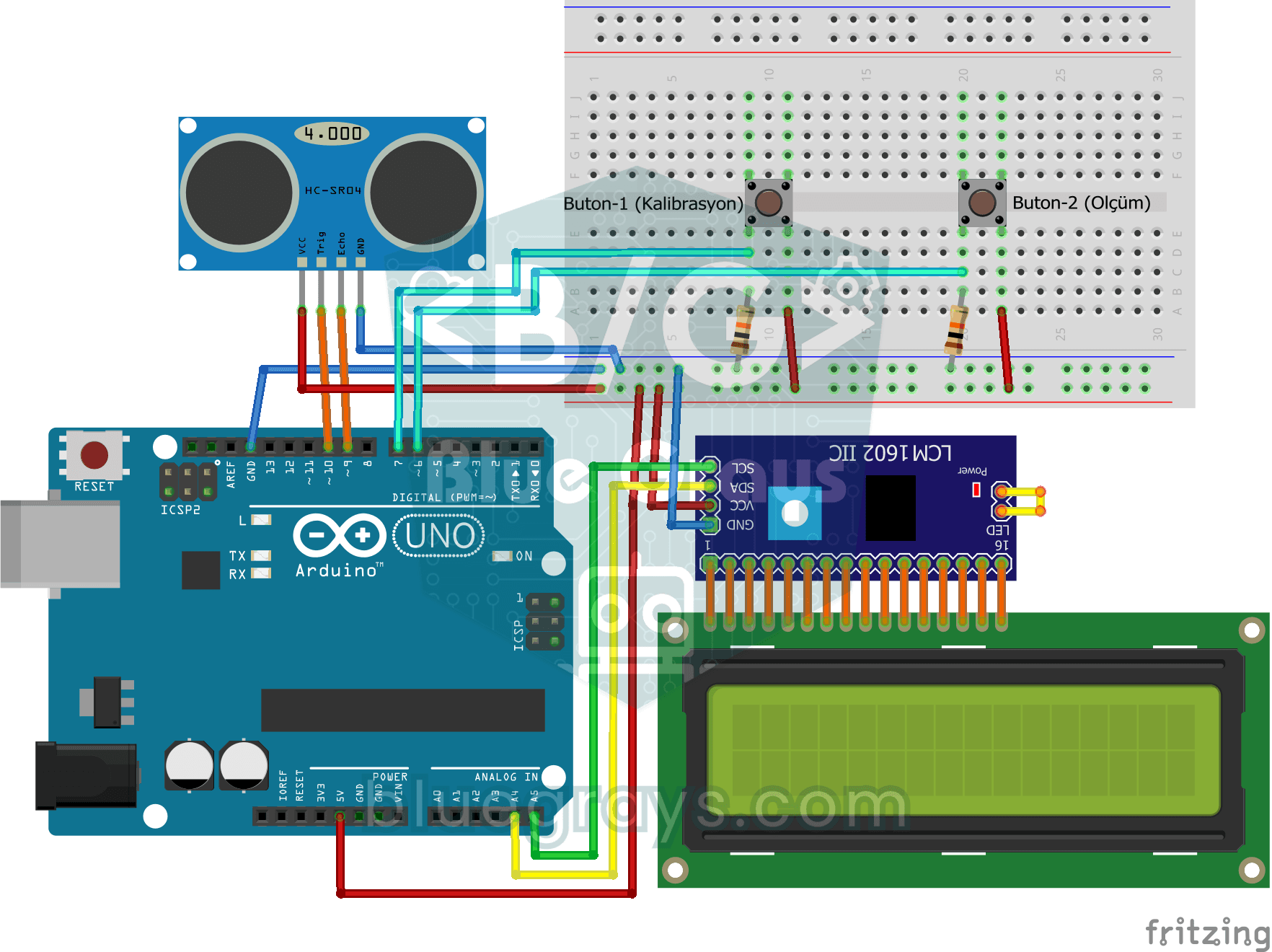
A height meter that hangs from a door frame and tells you, in centimetres, how tall the person standing under it is. First you press the first button with nobody underneath, and the distance sensor me
Servo Motor Operation with Potentiometer
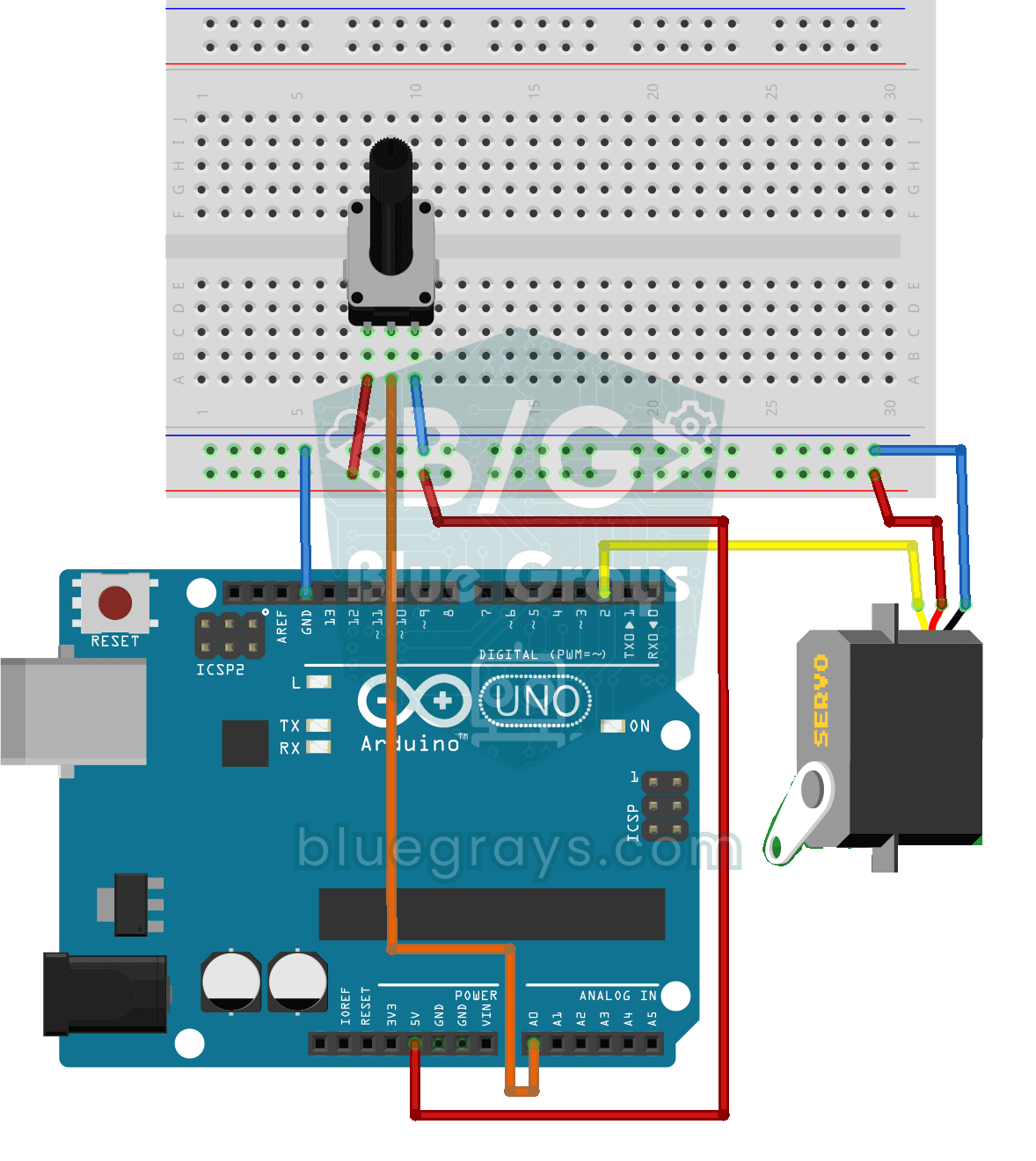
As you turn the potentiometer knob, the servo motor's arm turns right along with it: one end of the knob means zero degrees, the other end means half a turn. The Arduino keeps reading the knob's posit

Reading Light Intensity with the ESP32 LDR Module
Real-time monitoring of the LDR module's raw ADC value and relative light percentage calculated from dark and light reference values in the Serial Monitor. This percentage is not a lux measurement. Teaches the module’s calibration logic. It is ideal to complete this before Project 10, as it is used to determine the threshold value.

ESP32 HC-SR04 Ultrasonic Distance Sensor
The HC-SR04 ultrasonic sensor calculates distance by measuring the time it takes for the sound wave it emits to bounce off an object and return (Time of Flight). In this project, we will send a 10-microsecond pulse from the ESP32 to the sensor's TRIG pin and read the echo duration from the ECHO pin using pulseIn(). We will display the calculated distance in centimeters on a 16x2 I2C LCD. Since the HC-SR04 operates at 5V, a voltage divider is required on the ECHO pin—otherwise, the ESP32’s