
What Is an ADC? Analog-to-Digital Conversion with Arduino
What is an ADC and how does it work? Analog vs digital signals, 10- and 12-bit resolution, analogReference, voltage formula, ESP32 ADC2 and noise reduction.
An ADC (analog-to-digital converter) is the circuit that turns a continuously varying voltage on a pin into a number the microcontroller can work with. Every time you call analogRead() on an Arduino, this converter does the job in the background: the Arduino Uno's 10-bit ADC turns a voltage between 0 and 5 V into a number from 0 to 1023, while the 12-bit ADCs in the ESP32 and Raspberry Pi Pico turn roughly 0–3.3 V into a number from 0 to 4095. The ADC is the key to reading anything with an analog output: potentiometers, LDRs, soil moisture sensors, joysticks and temperature sensors.
In this guide you'll learn the difference between analog and digital signals, how an ADC turns a voltage into a number step by step, and how resolution and reference voltage affect your measurements. With real numbers, we'll work through the formula that converts a reading into volts, changing the measuring range with analogReference, sampling rate and practical ways to reduce noise. We'll also cover the ESP32's ADC, which isn't linear at the extremes, the ADC2 conflict with Wi-Fi and the attenuation setting, using the Raspberry Pi Pico's ADC with MicroPython, and finally give a short introduction to the DAC, which does the opposite job.
What is the difference between analog and digital signals?
An analog signal is a quantity that can take an infinite number of values within a range and changes continuously over time. As the voltage on a potentiometer's middle pin goes from 0 V to 5 V, it passes through every value in between, such as 1.2 V, 1.21 V and 1.215 V; the sound wave from a microphone, the temperature-dependent voltage of a thermistor and the slowly falling voltage of a battery are analog too. A digital signal, on the other hand, only knows specific levels. In the Arduino's world of logic there are two of them: LOW (0) and HIGH (1). On the Uno, a digital input treats anything below about 1.5 V as LOW and anything above 3.0 V as HIGH; the region in between is undefined. That's why digitalRead() can't tell 3.7 V from 4.2 V on a battery and calls both HIGH. The strength of a digital signal is its immunity to noise: 4.6 V and 5.0 V both mean the same HIGH. To measure, store or calculate with an analog value, you first have to turn it into a number, in other words a digital value, and the part that does this is the ADC.
What is an ADC and how does it work?
An ADC's job can be summed up in two steps. The first is sampling: at the moment of measurement the converter copies the input voltage onto a small capacitor (the sample-and-hold circuit) and holds it steady until the conversion is done; in the ATmega328P this capacitor is about 14 pF. The second is quantization: the held voltage is rounded to the nearest step on a scale that divides the reference voltage into equal steps, and the step number is returned as the result. The ADCs in the Arduino Uno, ESP32 and Pico are all of the successive approximation type (SAR, Successive Approximation Register). A SAR ADC works like a number-guessing game: it first tries half of the reference, sets the most significant bit to 1 if the input is higher and leaves it at 0 if it's lower, then tries half of the remaining range and repeats this for every bit. That's how a 10-bit ADC finds the right step out of 1024 possibilities with just 10 comparisons. For simplicity, the table below shows how a 4-bit ADC with a 5 V reference measures a 3.2 V input:
| Step | Bit tested | Comparison voltage | Is the input (3.2 V) higher? | Result bits |
|---|---|---|---|---|
| 1 | Bit 3 (worth 8) | 8 / 16 × 5 = 2.500 V | Yes → 1 | 1000 |
| 2 | Bit 2 (worth 4) | 12 / 16 × 5 = 3.750 V | No → 0 | 1000 |
| 3 | Bit 1 (worth 2) | 10 / 16 × 5 = 3.125 V | Yes → 1 | 1010 |
| 4 | Bit 0 (worth 1) | 11 / 16 × 5 = 3.4375 V | No → 0 | 1010 |
| Result | All bits done | 1010 = 10 → 10 × 5 / 16 = 3.125 V | Error 0.075 V (one step is 0.3125 V) | 1010 |
The 0.075 V difference in the result is the quantization error, and no ADC can escape it: if the real voltage lies between two steps, the ADC can only report one of them. The error stays below one step (LSB), so the smaller the step, the finer the measurement. Because the sample-and-hold capacitor has to charge for every measurement, the resistance of the source driving the ADC matters as well: the ATmega328P datasheet recommends an output impedance of about 10 kΩ or less, and a voltage divider with higher resistance can't charge the capacitor in time, so the readings drift. Besides the SAR type found in microcontrollers, there are other kinds of ADC. Sigma-delta ADCs are slow but very precise: the HX711 used in weighing projects offers 24 bits, and the I2C-connected ADS1115 module offers 16 bits. Flash ADCs use a separate comparator for every step; they're extremely fast and you'll find them in oscilloscopes.
ADC resolution: what do 10 bits and 12 bits mean?
Resolution tells you how many steps the ADC divides its measuring range into. An N-bit ADC produces 2^N steps: 10 bits means 1024 steps (0–1023), 12 bits 4096 steps (0–4095) and 16 bits 65,536 steps. The voltage of a single step is called the LSB (least significant bit) and is found with LSB = Vref / 2^N. On the Arduino Uno that's 5 V / 1024 = 4.88 mV, and on the ESP32 and Pico 3.3 V / 4096 = 0.81 mV. So the Uno can't see changes smaller than 4.88 mV; with an LM35 that outputs 10 mV/°C, that's a step of about 0.5 °C. But resolution and accuracy aren't the same thing. An ADC's noise, non-linearity and reference error make some of the bits on paper useless. The measure for this is the effective number of bits (ENOB): the RP2040's ADC in the Raspberry Pi Pico returns a 12-bit result, but according to its datasheet the effective number of bits is 8.7. Let's compare the ADCs of the three boards side by side:
| Feature | Arduino Uno R3 | ESP32 (WROOM-32) | Raspberry Pi Pico |
|---|---|---|---|
| ADC resolution | 10 bits (0–1023) | 12 bits (0–4095) | 12 bits (scaled to 0–65535 in MicroPython) |
| Analog inputs | 6 (A0–A5; A0–A7 on the Nano) | 18 channels: 8 on ADC1, 10 on ADC2 | 3 pins (GP26–GP28) + VSYS/3 (GP29) + temperature sensor |
| Default measuring range | 0–5 V | About 0–3.1 V (11 dB attenuation) | 0–3.3 V (ADC_VREF) |
| One step (LSB) | 4.88 mV | About 0.8 mV | 0.81 mV |
| Reference options | DEFAULT (5 V), INTERNAL (1.1 V), EXTERNAL (AREF) | Attenuation: 0, 2.5, 6 and 11 dB | External reference on the ADC_VREF pin |
| Sampling rate | About 10,000 readings/s | 20 kHz – 2 MHz in continuous (DMA) mode | 500,000 readings/s in hardware |
| Accuracy note | Absolute error ±2 LSB | Non-linear at the extremes, needs calibration | ENOB 8.7 bits, about 30 mV offset |
| Analog output (DAC) | None (PWM is used) | 2 channels, 8 bits (GPIO 25 and 26) | None (PWM is used) |
Formula for converting an ADC reading to voltage
The number the ADC returns means nothing on its own; to turn it into a voltage you use the reference voltage and the number of steps: Voltage = ADC value × Vref / 2^N. On the Arduino Uno that's V = value × 5.0 / 1024, so if analogRead() returned 512, the voltage on the pin is 512 × 5 / 1024 = 2.50 V. Going the other way, you find which number a given voltage corresponds to with value = V × 1024 / Vref: 3.3 V reads as about 675 on the Uno. In many examples you'll see a division by 1023 instead of 1024. The ATmega328P datasheet gives the formula ADC = Vin × 1024 / Vref; the largest value, 1023, represents one step below Vref. Dividing by 1023 makes the top value show exactly 5.00 V but shifts every value by about 0.1%. That difference is smaller than the ADC's own ±2 LSB error, so both work; what matters is being consistent within a project. The real big source of error is Vref itself: the 5V pin of a USB-powered Uno is often anywhere between 4.7 and 5.1 V, and writing 5.0 in the formula causes up to 5% error. So for precise measurements, measure the 5V pin with a multimeter and put the real value in your code. The ESP8266's only analog input (A0) is also 10 bits; the chip itself measures 0–1 V, and the built-in divider on boards like the NodeMCU and Wemos D1 Mini extends that range to about 0–3.2 V.
| Board and setting | Reading range | Converting to volts | Example |
|---|---|---|---|
| Arduino Uno / Nano (DEFAULT, 5 V) | 0–1023 | V = value × 5.0 / 1024 | 768 → 3.75 V |
| Uno, analogReference(INTERNAL) | 0–1023 | V = value × 1.1 / 1024 | 512 → 0.55 V |
| ESP32 (11 dB) | 0–4095 | Calibrated: analogReadMilliVolts() / 1000; rough: value × 3.3 / 4095 | 1650 mV → 1.65 V |
| Raspberry Pi Pico (read_u16) | 0–65535 | V = value × 3.3 / 65535 | 32768 → 1.65 V |
| ESP8266 NodeMCU / Wemos D1 Mini (A0) | 0–1023 | V = value × 3.2 / 1024 | 512 → 1.60 V |
Wiring a potentiometer: Arduino, ESP32 and Pico
| Potentiometer pin | Arduino Uno | ESP32 | Raspberry Pi Pico |
|---|---|---|---|
| Outer pin 1 | 5V | 3V3 | 3V3(OUT) (pin 36) |
| Middle pin (signal) | A0 | GPIO 34 (ADC1_CH6) | GP26 / ADC0 (pin 31) |
| Outer pin 2 | GND | GND | AGND (pin 33) or GND |
| Optional noise capacitor | 100 nF between A0 and GND | 100 nF between GPIO 34 and GND | 100 nF between GP26 and AGND |
Step by step: your first ADC reading with Arduino
- Build the circuit: Connect the outer pins of a 10 kΩ potentiometer to 5V and GND, and its middle pin to A0.
- Measure the 5V pin: Measure the voltage between 5V and GND with a multimeter and enter it in the VREF constant in the code (e.g. 4.93).
- Upload the code: Open the sketch below in the Arduino IDE, select your board and port, and upload it.
- Open the Serial Monitor: Set it to 9600 baud and watch the ADC value change between 0 and 1023 as you turn the knob (details in the Serial Monitor guide).
- Check: Measure between A0 and GND with the multimeter and compare it with the voltage on screen; the difference should stay around 10–20 mV.
1// Potansiyometreyi ADC ile okuma / Reading a potentiometer with the ADC
2// Kenar bacaklar 5V ve GND'ye, orta bacak A0'a / Outer legs to 5V and GND, wiper to A0
3const int POT_PIN = A0;
4const float VREF = 5.0;      // 5V pininde ölçtüğün gerilim / voltage you measured on the 5V pin
5
6void setup() {
7  Serial.begin(9600);
8}
9
10void loop() {
11  int raw = analogRead(POT_PIN);             // 0-1023 arası sayı / number between 0-1023
12  float volts = raw * VREF / 1024.0;         // sayıyı volta çevir / convert the number to volts
13  int percent = map(raw, 0, 1023, 0, 100);   // yüzdeye ölçekle / scale to percent
14
15  Serial.print(F("ADC: "));
16  Serial.print(raw);
17  Serial.print(F("  Gerilim / Voltage: "));
18  Serial.print(volts, 3);
19  Serial.print(F(" V  Yuzde / Percent: "));
20  Serial.println(percent);
21  delay(200);
22}
analogRead() completes a measurement in about 100 µs and returns an integer between 0 and 1023. The code first converts this number into volts with the formula, then into a percentage with map(). Because map() uses integer arithmetic, it drops the fractional part; if you need a decimal result, do the calculation yourself with float. This is a ratiometric measurement: since the potentiometer and the ADC are powered from the same 5 V, the knob position, and therefore the ADC value, doesn't change even if the supply drops to 4.9 V; only the calculated voltage changes. The same goes for sensors read through a divider, like LDRs and NTCs. On the other hand, when you measure a battery's voltage or a sensor with a fixed mV output like the LM35, the real value of Vref goes straight into the result.
Reference voltage and analogReference
The reference voltage (Vref) is the top of the ADC's scale: if the input voltage equals or exceeds Vref, the result sticks at the maximum value (1023). Lowering Vref narrows the measuring range but makes every step smaller, so you measure small signals more finely. On the Arduino Uno you choose the reference with the analogReference() function. With the INTERNAL option Vref becomes 1.1 V and one step drops to 1.07 mV; you can read an LM35 (10 mV/°C) in steps of about 0.1 °C, but in exchange nothing above 1.1 V, i.e. 110 °C, can be measured. The internal 1.1 V reference itself can vary between 1.0 and 1.2 V from chip to chip, so precise projects need a one-time calibration with a multimeter. The first few readings after changing the reference may be inaccurate, as the Arduino documentation also notes, so discarding a few readings after switching is a good habit. The reference setting also affects all of the board's analog pins at once. The options differ from board to board:
| Option | Reference | Boards | When to use it |
|---|---|---|---|
| DEFAULT | 5 V (3.3 V on 3.3 V boards) | Uno, Nano, Mega, Leonardo | Sensors that are ratiometric to the supply, like potentiometers, LDRs and joysticks |
| INTERNAL | 1.1 V (ATmega328P); 2.56 V on the Leonardo | Uno, Nano, Leonardo (not on the Mega) | Low-voltage sensors such as the LM35 |
| INTERNAL1V1 / INTERNAL2V56 | 1.1 V / 2.56 V | Mega only | Small signals on the Mega |
| EXTERNAL | The voltage on the AREF pin (0–5 V) | Uno, Nano, Mega | Using your own precision reference (e.g. 2.5 V or 4.096 V) |
| AR_INTERNAL | About 1.43 V (the chip's internal reference) | Uno R4 Minima and WiFi | Small signals on the Uno R4 |
Sampling rate: how many readings can an ADC take per second?
The sampling rate is how many measurements the ADC can take in one second. On the Arduino Uno, the ADC clock is set to 125 kHz by dividing 16 MHz by 128, and one conversion takes 13 clock cycles; that's why analogRead() takes about 100 µs and you can make at most around 10,000 readings per second. That's more than enough for slowly changing quantities like temperature, light or battery voltage; often even 10 readings per second will do. For fast signals, the Nyquist rule comes into play: to capture a signal without losing it, you have to sample at least twice as fast as its highest frequency, and in practice 5–10 times is preferred. To see 50 Hz mains hum you need at least 100 readings/s, and to record speech up to 4 kHz at least 8,000 readings/s. If you need faster readings on the Uno, you can lower the ADC prescaler: putting ADCSRA = (ADCSRA & 0xF8) | 0x04; in setup() sets the prescaler to 16, the ADC clock rises to 1 MHz and analogRead() drops to about 16 µs, at the cost of some accuracy. On the ESP32, individual analogRead() calls allow tens of thousands of readings per second, and in continuous mode with DMA (analogContinuous() in Arduino) you can choose a rate between 20 kHz and 2 MHz; this mode only works with ADC1 pins. The Raspberry Pi Pico's ADC runs on its own 48 MHz clock, finishes each conversion in 96 cycles, i.e. 2 µs, and reaches 500,000 readings per second; a MicroPython loop can't keep up with that, and for full speed you need the C SDK and DMA.
ESP32 ADC: non-linearity, the ADC2 and Wi-Fi conflict, and attenuation
On paper, the ESP32's 12-bit ADC measures four times more finely than the Uno, but in practice there are three things to watch. The first is non-linearity: near 0 V the ESP32's ADC reads 0 up to about 100–150 mV, and at the top end it saturates at 4095 before the input reaches 3.3 V; the curve in between isn't a perfect straight line either. The second is reference variation: by design the ESP32's internal reference is 1100 mV, but according to Espressif it varies between 1000 and 1200 mV from chip to chip, which means an error of roughly ±9% in uncalibrated readings. That's why Espressif writes calibration data into the chips' eFuses during production. The Arduino analogReadMilliVolts() function uses this data to convert the raw value directly into calibrated millivolts, and in most cases it's far more accurate than calculating analogRead() × 3.3 / 4095. The third is attenuation: the ADC core can only measure up to about 1 V, so higher voltages are scaled down by an adjustable attenuator at the input. The Arduino default is 11 dB, which allows readings up to about 3.1 V, but the accurate range Espressif recommends for this setting is 150–2450 mV. For small signals, lowering the attenuation improves both accuracy and resolution:
| Attenuation | Arduino constant | Accurate range | Use |
|---|---|---|---|
| 0 dB | ADC_0db | 100–950 mV | Small signals, finest measurement |
| 2.5 dB | ADC_2_5db | 100–1250 mV | Sensor outputs around 1 V |
| 6 dB | ADC_6db | 150–1750 mV | Medium-level signals |
| 11 dB (default) | ADC_11db | 150–2450 mV (readings continue to about 3.1 V) | Potentiometers and 0–3.3 V sensors |
1// ESP32 ADC: ham değer ve kalibre milivolt / ESP32 ADC: raw value and calibrated millivolts
2// Potansiyometre: 3V3, GND ve orta bacak GPIO 34 / Pot: 3V3, GND and wiper to GPIO 34
3const int POT_PIN = 34;      // ADC1_CH6, Wi-Fi açıkken de çalışır / ADC1_CH6, works with Wi-Fi on
4
5void setup() {
6  Serial.begin(115200);
7  analogReadResolution(12);                     // 0-4095 (varsayılan / default)
8  analogSetPinAttenuation(POT_PIN, ADC_11db);   // yaklaşık 3,1 V'a kadar / up to about 3.1 V
9}
10
11void loop() {
12  uint32_t rawSum = 0;
13  uint32_t mvSum = 0;
14  for (int i = 0; i < 16; i++) {                // 16 ölçümün ortalaması / average of 16 readings
15    rawSum += analogRead(POT_PIN);              // ham ADC değeri / raw ADC value
16    mvSum += analogReadMilliVolts(POT_PIN);     // eFuse kalibrasyonlu mV / eFuse-calibrated mV
17  }
18  float raw = rawSum / 16.0;
19  float naiveV = raw * 3.3 / 4095.0;            // basit formül / naive formula
20  float calibratedV = mvSum / 16.0 / 1000.0;    // kalibre edilmiş / calibrated
21
22  Serial.printf("Ham / Raw: %4.0f  Formul / Formula: %.3f V  Kalibre / Calibrated: %.3f V\n",
23                raw, naiveV, calibratedV);
24  delay(500);
25}
The code shows two results side by side: the raw value converted with the simple formula and the value calibrated by analogReadMilliVolts(). As you turn the potentiometer towards either end, you'll notice the difference grow, and at the very bottom, where the formula shows 0.000 V, the multimeter still measures around 0.1 V. analogSetPinAttenuation() changes the attenuation for a single pin, while analogSetAttenuation() changes it for all pins. The ESP32 is noticeably noisier than the Uno, especially while Wi-Fi is transmitting; Espressif's own advice is to add a 100 nF capacitor at the input and average several samples, which is what the 16-reading average in the code does. Newer chips like the ESP32-S3 and ESP32-C3 use a more advanced curve-fitting calibration, but pin numbers and ADC2 rules vary by model, so always check your board's pin map (Pinout tool). We explain how to build a divider for measuring voltages above 3.3 V in the voltage divider guide.
ADC on the Raspberry Pi Pico (MicroPython)
The Raspberry Pi Pico has three analog inputs you can use from outside: GP26 (ADC0), GP27 (ADC1) and GP28 (ADC2). GP29 (ADC3) measures a third of the VSYS supply voltage on the board, and ADC4 is connected to the chip's internal temperature sensor. MicroPython's read_u16() function scales the 12-bit result to the 0–65535 range so the same code works across different boards, but the real resolution is still 4096 steps. The RP2040 has no separate reference voltage; it uses its own ADC supply as the reference. On the Pico, this supply (ADC_VREF, pin 35) is derived from the output of the 3.3 V switching regulator (SMPS), filtered through a resistor of about 200 Ω. The Raspberry Pi board datasheet spells out three consequences: the accuracy of the 3.3 V is limited, the supply is somewhat noisy, and the current the ADC draws creates an offset of about 30 mV. The fixes are in the same document: drive GP23 high to put the regulator into its lower-ripple PWM mode, tie an unused ADC channel to AGND and subtract its reading as the offset, and for much better accuracy connect a 3.0 V reference such as the LM4040 between ADC_VREF and AGND (the measuring range then becomes 0–3.0 V). The RP2040's ADC is also known to have small jumps (DNL errors) at the values 512, 1536, 2560 and 3584; averaging several readings reduces their effect. On the Pico W, GP23 is reserved for the wireless chip and the regulator mode is controlled through WL_GPIO1, so delete the GP23 lines in the code below on a Pico W.
1from machine import ADC, Pin
2import time
3
4pot = ADC(26)                 # GP26 = ADC0 (pin 31)
5chip_temp = ADC(4)            # dahili sıcaklık sensörü / internal temperature sensor
6VREF = 3.3                    # ADC_VREF; multimetreyle ölçüp düzelt / measure and correct with a multimeter
7
8# Yalnız Pico ve Pico 2 (W değil): SMPS PWM moduna, daha az gürültü / Plain Pico and Pico 2 only (not W): SMPS to PWM mode, less noise
9smps_mode = Pin(23, Pin.OUT)
10smps_mode.value(1)
11
12
13def read_average(adc, samples=16):
14    total = 0
15    for _ in range(samples):
16        total += adc.read_u16()           # 0-65535 (12 bit ölçeklenmiş / 12-bit scaled)
17    return total / samples
18
19
20while True:
21    raw = read_average(pot)
22    volts = raw * VREF / 65535            # sayıyı volta çevir / convert the number to volts
23    t_volts = read_average(chip_temp) * VREF / 65535
24    temp_c = 27 - (t_volts - 0.706) / 0.001721    # RP2040 veri sayfası formülü / RP2040 datasheet formula
25    print("ADC: {:5d}  {:.3f} V  Yonga / Chip: {:.1f} C".format(int(raw), volts, temp_c))
26    time.sleep(0.5)
Ways to reduce ADC noise
Even when measuring a steady voltage, it's normal for the ADC value to wobble by a step or two; quantization, ripple on the supply, interference picked up by long wires and nearby motors or Wi-Fi transmissions all contribute. On the Uno, a wobble of ±1–2 steps is considered healthy; much more than that usually points to a problem in the circuit. You can fight noise in both hardware and software:
- Add a capacitor: A 100 nF ceramic capacitor between the analog pin and GND filters out fast interference and gives the sample-and-hold capacitor a ready charge with high-resistance sources.
- Keep wires short: If the sensor cable is long, twist the signal and GND wires together; route motor and relay wires away from analog lines.
- Get the grounding right: Don't let the return current of high-current loads like motors, relays and LED strips flow through the sensor's GND wire; join the grounds at a single point (star grounding).
- Use a clean reference: USB power is noisy; for absolute voltage measurements, the internal reference or an external reference IC gives more stable results.
- Discard the first reading after switching channels: The multiplexer at the ADC input can carry charge over from the previous channel; when reading several pins in turn, throw away one reading on each pin.
- Average: Averaging N readings reduces random noise by about √N; 16 readings cut the noise to a quarter.
- Oversampling: If you add up 4^n readings and shift the result right by n bits, you gain n extra bits of resolution; shifting the sum of 16 readings by 2 bits turns the Uno's 10 bits into 12. For this to work, the signal needs at least one step of natural noise.
- Median and exponential filters: A median filter removes sudden spikes caused by motors, while an exponential moving average (EMA) gives a smooth curve using very little memory.
1// Ham, ortalama ve EMA filtreli ADC değerleri / Raw, averaged and EMA-filtered ADC values
2// Serial Plotter ile izle / Watch with the Serial Plotter
3const int SENSOR_PIN = A0;
4const float ALPHA = 0.1;     // EMA katsayısı (0-1) / EMA coefficient (0-1)
5float ema = 0;
6
7void setup() {
8  Serial.begin(115200);
9  analogRead(SENSOR_PIN);              // ilk okumayı at / discard the first reading
10  ema = analogRead(SENSOR_PIN);        // filtreyi başlat / seed the filter
11}
12
13void loop() {
14  int raw = analogRead(SENSOR_PIN);    // ham değer / raw value
15
16  long sum = 0;
17  for (int i = 0; i < 16; i++) {       // 16 ölçüm topla / sum 16 readings
18    sum += analogRead(SENSOR_PIN);
19  }
20  float average = sum / 16.0;          // ortalama (0-1023) / average (0-1023)
21
22  ema += ALPHA * (raw - ema);          // üstel hareketli ortalama / exponential moving average
23
24  Serial.print(F("ham:"));
25  Serial.print(raw);
26  Serial.print(F(" ortalama:"));
27  Serial.print(average);
28  Serial.print(F(" ema:"));
29  Serial.println(ema);
30  delay(20);
31}
When you upload the code and open the Serial Plotter in the Arduino IDE, you'll see three lines: the raw value jitters, the average of 16 readings is clearly calmer, and the EMA is the smoothest curve but reacts to changes a little later. The ALPHA coefficient is chosen between 0 and 1: 0.1 means each new reading contributes 10% to the result, so roughly the last 10 readings have an effect; increase it and the response gets faster but the noise grows. Which filter to choose depends on the signal; a strong EMA suits a slowly changing temperature, while a short average is better for a joystick that needs a fast response. We compare moving averages, median filters and hysteresis with real sensor examples in the sensor data filtering guide.
A short introduction to the DAC: from digital to analog
A DAC (digital-to-analog converter) does the opposite of an ADC: it takes a number and produces a voltage proportional to it. Write 0 to an 8-bit DAC and you get 0 V, write 255 and you get close to the supply voltage, write 128 and you get about half of it. The simplest DACs are built with a resistor ladder called R-2R. Let's clear up a common mix-up here: analogWrite() on the Arduino Uno isn't a DAC, it produces PWM; the pin actually switches rapidly between 0 V and 5 V. That's fine for LED brightness and motor speed, but if you really need a steady voltage, you have to add an RC low-pass filter to the PWM output; you can calculate the filter's time constant with the RC time constant tool. As for boards with a real DAC: the ESP32 has two 8-bit DACs on GPIO 25 and GPIO 26, used with dacWrite(pin, value), while the ESP32-S3 and ESP32-C3 have no DAC. The Arduino Uno R4 has a 12-bit DAC on pin A0. For the Uno R3, Nano and Pico, the easiest route is the 12-bit MCP4725 module connected over I2C. With a DAC you can generate sound, output sine or triangle waves, and even connect the DAC output to an ADC input to test the ADC with known voltages:
1// ESP32 DAC ile sinüs dalgası / Sine wave with the ESP32 DAC
2// Çıkış GPIO 25'te, osiloskopla izle / Output on GPIO 25, watch it with an oscilloscope
3const int DAC_PIN = 25;      // DAC1 = GPIO 25 (DAC2 = GPIO 26)
4const int STEPS = 64;        // bir periyottaki nokta sayısı / points per period
5uint8_t sineTable[STEPS];
6
7void setup() {
8  for (int i = 0; i < STEPS; i++) {
9    sineTable[i] = 128 + 127 * sin(2 * PI * i / STEPS);  // 1-255 arası tablo / table between 1-255
10  }
11}
12
13void loop() {
14  for (int i = 0; i < STEPS; i++) {
15    dacWrite(DAC_PIN, sineTable[i]);   // 0 → 0 V, 255 → yaklaşık 3,3 V / 0 → 0 V, 255 → about 3.3 V
16    delayMicroseconds(150);            // yaklaşık 100 Hz / roughly 100 Hz
17  }
18}
Project ideas with the ADC
- Digital voltmeter: Measure 0–25 V with a voltage divider and show the result on an LCD; the steps are in the Arduino voltmeter guide.
- Automatic night light: Read the voltage of an LDR and switch the LEDs on when it gets dark.
- Smart plant pot: Use the analog output of a soil moisture sensor to run a pump when the soil dries out.
- Joystick-controlled robot: A joystick's two axes are two separate analog inputs; turn their values into motor speed and direction.
- Current meter: Read the current-proportional voltage of an ACS712 to see how much current a device draws.
- Sound level meter: Sample the analog output of a KY-038 sound sensor quickly and light an LED bar according to the peak value.
- Battery gauge: Measure the voltage in a battery-powered project and show the remaining charge as a percentage on a display.
Common mistakes and how to fix them
| Symptom | Likely cause | Fix |
|---|---|---|
| The value jumps around randomly with nothing connected | The pin is floating | Connect the sensor; don't read unused pins, or pull them to GND |
| The value sticks at 1023 (4095 on the ESP32) | The input is above the reference, or INTERNAL is selected | Adjust the reference or attenuation, bring high voltages down with a divider |
| On the ESP32, analogRead() returns 0 once Wi-Fi is on | The sensor is on an ADC2 pin | Use the ADC1 pins, GPIO 32–39 |
| The ESP32 shows 0 for small voltages and 4095 for large ones | The ADC isn't linear at the extremes | Use analogReadMilliVolts() and keep the signal within 150–2450 mV |
| The calculated voltage differs from the multimeter by 3–5% | Vref isn't 5.00 V (USB power) | Measure the 5V pin and put it in VREF, or add a calibration factor |
| Reading two pins in turn, the values affect each other | Multiplexer and high source resistance | Discard the first reading after switching, keep the source below 10 kΩ, add 100 nF |
| The values jump when a motor or relay runs | Noise on the shared GND line, supply sagging | Give the loads their own GND return, use capacitors and a median filter |
| Readings went wrong after applying a voltage to AREF | AREF was used without calling analogReference(EXTERNAL) | Select EXTERNAL first, or connect to AREF through a 5 kΩ resistor |
| After selecting INTERNAL, the potentiometer hits 1023 halfway | The 1.1 V reference affects all analog pins | Switch back to DEFAULT before reading ratiometric sensors and discard a few readings |
| On the Pico, the reading is above 0 even with the input at GND | ADC offset and ADC_VREF noise | Tie a channel to AGND, measure the offset and subtract it; drive GP23 high |
The ADC is the bridge between the physical world and your code: once you know its resolution, reference voltage and sampling rate, you also know what every number on the screen represents and how far you can trust it. Measure the reference properly on the Uno, use the ADC1 pins and analogReadMilliVolts() on the ESP32, take the offset and noise into account on the Pico, then calm the result down with averaging and filters. In the BlueGrays app you'll find projects built on analog readings, such as reading light intensity with an LDR, a digital voltmeter with an LCD, temperature measurement with an NTC and controlling a servo and LED brightness with a potentiometer, each with step-by-step circuit diagrams and code.
Frequently asked questions
What is an ADC and what is it used for?
An ADC (analog-to-digital converter) is the circuit that turns the voltage on a pin into a number the microcontroller can process. It's used to read parts with an analog output, such as potentiometers, LDRs and temperature and humidity sensors. On an Arduino, the analogRead() command runs this converter.
What is the difference between analog and digital signals?
An analog signal can take any value within a range and changes continuously, while a digital signal consists only of specific levels, LOW and HIGH on an Arduino. digitalRead() only tells you whether a pin is 0 or 1, whereas analogRead() tells you how much voltage there is as a number.
Why does Arduino analogRead return values from 0 to 1023?
The Arduino Uno's ADC is 10-bit and produces 2^10 = 1024 different steps, numbered from 0 to 1023. A value of 0 represents 0 V, and 1023 represents one step below the reference voltage (usually 5 V). The 12-bit ADCs in the ESP32 and Pico return values from 0 to 4095.
How do you convert an ADC value to voltage?
Use the formula voltage = ADC value × reference voltage / number of steps. On the Arduino Uno that's V = value × 5.0 / 1024; on the ESP32, analogReadMilliVolts() gives calibrated millivolts directly. On the Pico, use V = value × 3.3 / 65535 for MicroPython's read_u16() value.
Do the ESP32 ADC2 pins work with Wi-Fi?
No. On the ESP32, the Wi-Fi driver also uses the ADC2 unit, so you can't read from the ADC2 pins (GPIO 0, 2, 4, 12–15, 25–27) while Wi-Fi is on. In Wi-Fi projects, connect analog sensors to the ADC1 pins (GPIO 32–39).
What is a DAC and how is it different from an ADC?
A DAC (digital-to-analog converter) does the opposite of an ADC: it turns a number into a voltage. An ADC is used to measure the voltage coming from a sensor, a DAC to produce a voltage such as sound or a signal. The Arduino Uno has no DAC and analogWrite() produces PWM; the ESP32 has two 8-bit DACs on GPIO 25 and 26, and the Uno R4 has a 12-bit DAC on A0.
Projects to build after reading this
See all projects
Measuring Light Intensity with an LDR
Want to see how bright your room is as a number? The LDR, a small part that reacts to light, measures the light around it, and the Arduino writes the value to your computer screen every half second. C
Digital Voltmeter with LCD Display
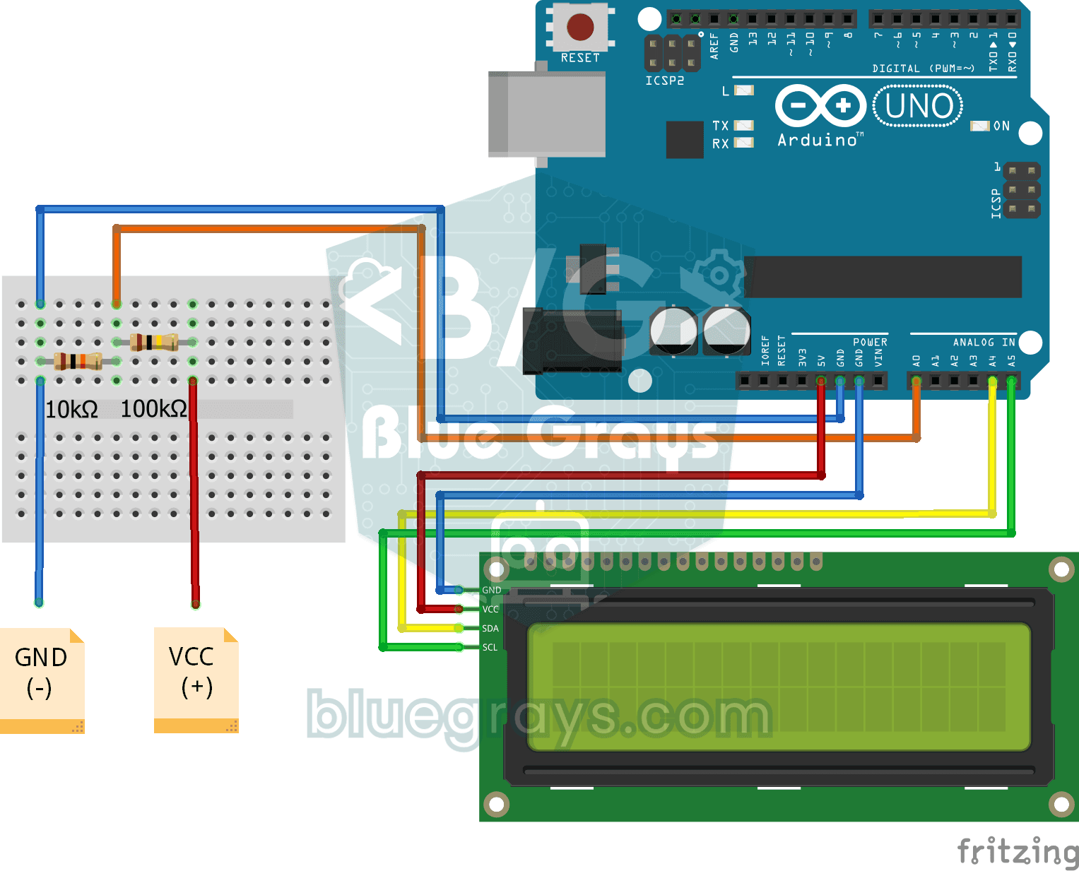
Find out how much voltage a battery or power adapter gives with a meter you built yourself. A divider made of two resistors brings high voltage down to a level the board can read, and the Arduino calc

Reading Light Intensity with the ESP32 LDR Module
Real-time monitoring of the LDR module's raw ADC value and relative light percentage calculated from dark and light reference values in the Serial Monitor. This percentage is not a lux measurement. Teaches the module’s calibration logic. It is ideal to complete this before Project 10, as it is used to determine the threshold value.

ESP32 LED Brightness Control with a Potentiometer (Analog → PWM)
In this project, we control the brightness of an LED analogically using a potentiometer. The ESP32's ADC pin reads the 0-3.3V voltage from the potentiometer, and this value is then converted into a PWM (Pulse Width Modulation) signal and sent to the LED. As a result, as you turn the potentiometer, the LED gradually brightens and dims. With Arduino Core 3.0+, analogWrite() can be used directly; on the ESP32-S2/S3, the ADC resolution is fixed at 12-bit.
Temperature Measurement with NTC and 2x16 Lcd Display
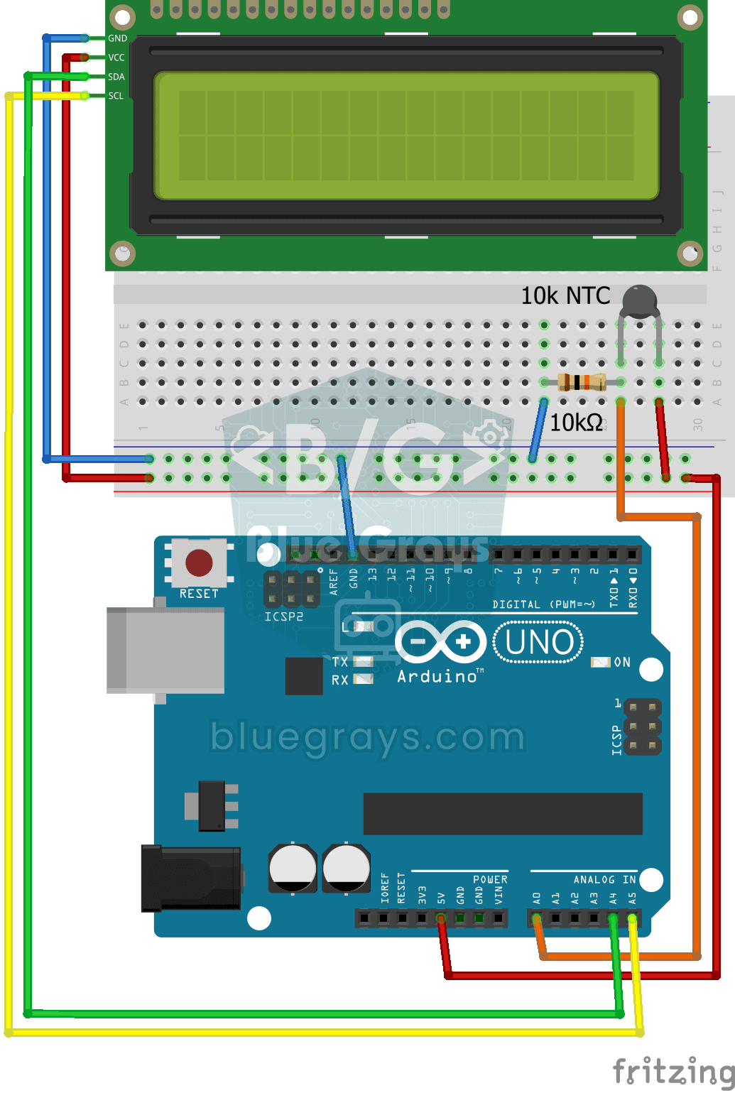
Measure the temperature around you with a sensor that looks like a tiny bead. This part, called an NTC, lets electricity through more easily as it warms up; the Arduino reads that change, turns it int
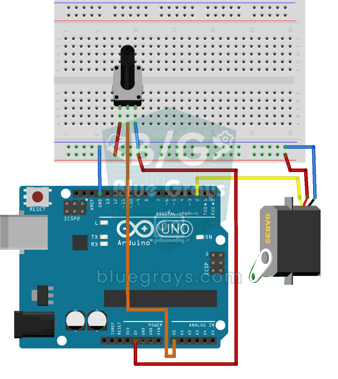
Servo Motor Operation with Potentiometer
As you turn the potentiometer knob, the servo motor's arm turns right along with it: one end of the knob means zero degrees, the other end means half a turn. The Arduino keeps reading the knob's posit
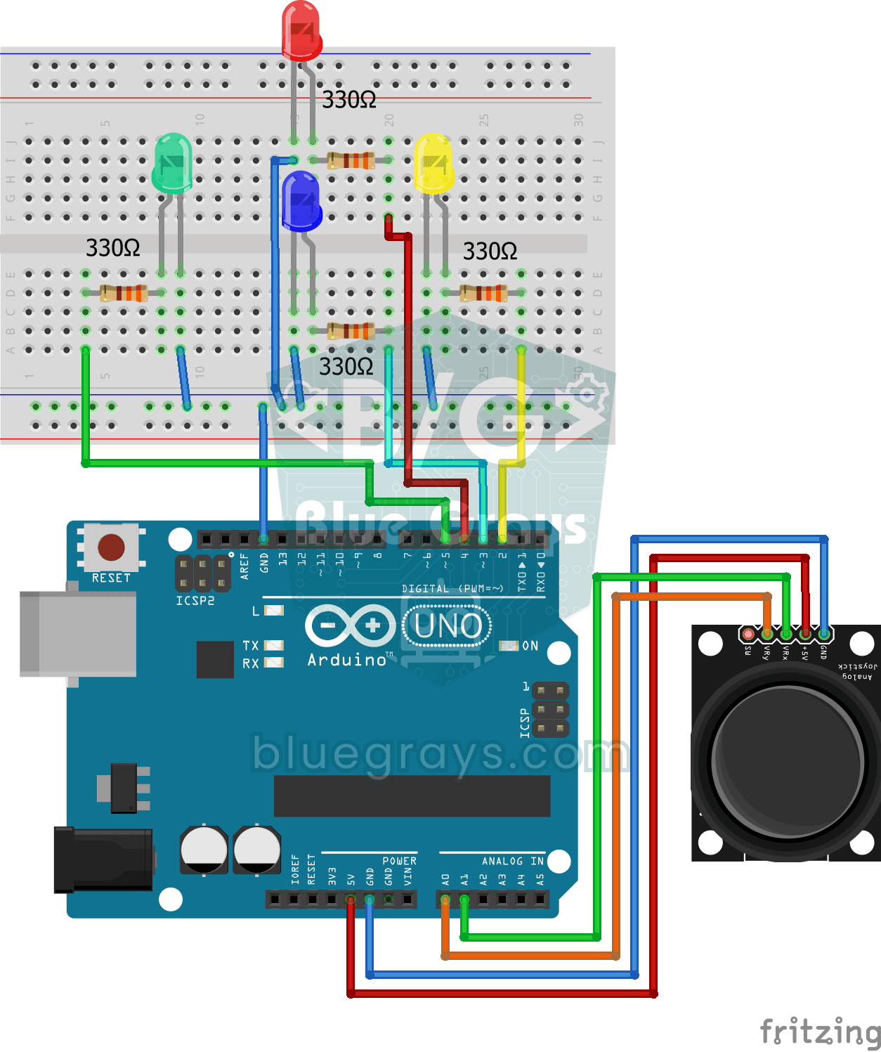
Led Control with Joystick
Push the little stick on the joystick all the way in any direction and the LED for that direction lights up: there are four different colours for right, left, up and down. Let go of the stick, it spri

ESP32 Color Mixer Light (3 Potentiometers + RGB LED + OLED)
A smart color-mixing lamp that lets you mix any color you want by turning three potentiometers with the ESP32! As you turn the red, green, and blue potentiometers, the common-cathode RGB LED changes color in real time. The SSD1306 OLED display shows real-time values for each color in the 0–255 range, visual fill bars, and the HEX web color code (such as #FF8040). A mini professional color studio—teaches RGB color theory, ADC analog reading, brightness control via PWM, and I2C display design all