
Binary Number System: Hex, Bits and Bitwise Operations on Arduino
Binary number system, hex and decimal conversions, bits and bytes, 0b and 0x on Arduino, &, |, ^, ~, <<, >> with bitRead, plus 74HC595 and register examples.

The binary number system uses only the digits 0 and 1 and is the foundation of all digital electronics. Every pin, every register and every byte in an Arduino's memory is really a binary number made of switches that are on or off: 1 means a pin is HIGH and 0 means it is LOW. Expressions you meet in code such as 0b10110101, 0xB5 or PORTB |= (1 << 5) may look scary, but once you understand binary and hexadecimal they all come down to a few simple rules.
In this guide you'll first see how to convert decimal, binary and hexadecimal numbers into each other by hand, what bits, nibbles and bytes are, and how negative numbers are stored in memory. Then you'll learn to write numbers on Arduino with 0b and 0x, read and change a single bit with AND, OR, XOR, NOT and shift operations, and use the bitRead, bitWrite and bitSet functions. Finally you'll prepare bytes for a 7-segment display and a 74HC595, and write directly to registers on the Uno, ESP32 and Pico.
What is a number system? Decimal, binary and hexadecimal
The decimal system we use every day has 10 digits, and each position is worth 10 times the one before: 181 is 1×100 + 8×10 + 1×1. The binary system has only two digits and each position is worth twice the one before; from right to left the place values are 1, 2, 4, 8, 16, 32, 64, 128. The hexadecimal system (hex for short) has 16 digits: after 0–9 come A=10, B=11, C=12, D=13, E=14, F=15. Hex is so popular in electronics because each hex digit corresponds to exactly 4 bits; it's the most practical way to write long binary numbers in a short, readable form.
| Decimal | Binary | Hex | Decimal | Binary | Hex |
|---|---|---|---|---|---|
| 0 | 0000 | 0 | 8 | 1000 | 8 |
| 1 | 0001 | 1 | 9 | 1001 | 9 |
| 2 | 0010 | 2 | 10 | 1010 | A |
| 3 | 0011 | 3 | 11 | 1011 | B |
| 4 | 0100 | 4 | 12 | 1100 | C |
| 5 | 0101 | 5 | 13 | 1101 | D |
| 6 | 0110 | 6 | 14 | 1110 | E |
| 7 | 0111 | 7 | 15 | 1111 | F |
Conversions: between decimal, binary and hex
To convert decimal to binary, keep dividing the number by 2 and note the remainders; reading the remainders from bottom to top gives the binary number. For 181: 181/2 = 90 remainder 1, 90/2 = 45 remainder 0, 45/2 = 22 remainder 1, 22/2 = 11 remainder 0, 11/2 = 5 remainder 1, 5/2 = 2 remainder 1, 2/2 = 1 remainder 0, 1/2 = 0 remainder 1. Reading from bottom to top gives 10110101. Converting binary to decimal is easier: add up the place values of the positions that hold a 1. 10110101 = 128 + 32 + 16 + 4 + 1 = 181.
| Place value | 128 | 64 | 32 | 16 | 8 | 4 | 2 | 1 |
|---|---|---|---|---|---|---|---|---|
| 10110101 (181) | 1 | 0 | 1 | 1 | 0 | 1 | 0 | 1 |
| 00001100 (12) | 0 | 0 | 0 | 0 | 1 | 1 | 0 | 0 |
| 11111111 (255) | 1 | 1 | 1 | 1 | 1 | 1 | 1 | 1 |
To convert binary to hex, split the bits into groups of four starting from the right and replace each group with its hex digit from the table: 1011 0101 → B 5 → 0xB5. The reverse is just as easy: 0x3C → 0011 1100. To convert hex to decimal, multiply each digit by a power of 16: 0xB5 = 11×16 + 5 = 181, 0x3FF = 3×256 + 15×16 + 15 = 1023. The last example should look familiar: the upper limit of the Uno's 10-bit analogRead value is 1023, which is ten 1s. You'll find the link between analog readings and bit counts in the ADC article.
Bits, nibbles, bytes and value ranges
A single binary digit is called a bit. 4 bits make a nibble, which is one hex digit; 8 bits make a byte, written with two hex digits. The rightmost bit in a byte is the least significant bit (LSB, bit 0) and the leftmost is the most significant bit (MSB, bit 7). Bit numbers always start at 0, so the bits of an 8-bit number are numbered 0–7. With n bits you can write 2ⁿ different values: 8 bits give 256, 10 bits 1024 and 16 bits 65536 different values.
| Size | Arduino type | Unsigned range | Signed range |
|---|---|---|---|
| 8 bits (1 byte) | byte, uint8_t / int8_t | 0–255 | -128 to 127 |
| 16 bits (2 bytes) | int on the Uno, word, uint16_t | 0–65535 | -32768 to 32767 |
| 32 bits (4 bytes) | long, uint32_t; int on the ESP32 and Pico | 0–4,294,967,295 | -2,147,483,648 to 2,147,483,647 |
Negative numbers: two's complement
Microcontrollers store negative numbers using two's complement: in a signed number, if the leftmost bit is 1 the number is negative. To get the negative of a number you invert all its bits and add 1. 5 = 00000101; inverted 11111010; add 1 and you get 11111011 = 0xFB, which is -5. The same bit pattern is a different number depending on how you read it: 0xFF is 255 as a byte and -1 as an int8_t. That's why assigning raw bytes from a sensor to the right type matters so much. When a variable passes its upper limit it also wraps around: in a byte 255 + 1 = 0, and with int on the Uno 32767 + 1 = -32768; this is called overflow.
Writing numbers with 0b, 0x and B on Arduino
In Arduino code you can write the same number in three ways and it makes no difference to the compiler: 181 (decimal), 0b10110101 (binary, standard since C++14) and 0xB5 (hexadecimal). Arduino also recognises the B10110101 form left over from older code, but these are constants defined only for 8-bit values, and 0b is better in new code. Which form to choose depends on readability: binary is clearest for LED patterns and register settings, hex for addresses and colour codes, and decimal for measurements.
1// Aynı sayının üç yazımı ve Seri Monitör'de gösterimi
2// Three ways to write the same number and print it
3void binaryYaz(byte deger) {               // baştaki sıfırlarla 8 bit yaz / print 8 bits with leading zeros
4  for (int i = 7; i >= 0; i--) {
5    Serial.print(bitRead(deger, i));
6  }
7  Serial.println();
8}
9
10void setup() {
11  Serial.begin(9600);
12  byte a = 0b10110101;                       // ikilik / binary
13  byte b = 0xB5;                             // onaltılık / hex
14  byte c = 181;                              // onluk / decimal
15  Serial.println(a == b && b == c ? "Ucu de ayni / All equal" : "Farkli / Different");
16  Serial.println(c, BIN);                    // 10110101
17  Serial.println(c, HEX);                    // B5
18  Serial.println(c, DEC);                    // 181
19  Serial.println(12, BIN);                   // 1100 (baştaki sıfırlar yok / no leading zeros)
20  binaryYaz(12);                             // 00001100
21  Serial.println(010);                       // 8: baştaki 0 sekizlik demek / leading 0 means octal
22}
23
24void loop() {
25}Bitwise operations: &, |, ^, ~, << and >>
Bitwise operations compare the bits in the same position of two numbers one by one. AND (&) gives 1 only if both bits are 1; OR (|) gives 1 if either bit is 1; XOR (^) gives 1 if the bits differ; NOT (~) inverts every bit. Left shift (<<) pushes the bits to the left and adds 0s on the right, multiplying the number by 2 at each step; right shift (>>) pushes the bits to the right, dividing by 2 at each step. These are the software counterparts of logic gates; you can see their truth tables in the logic gates article and the logic gate tool. The table below shows the results for a = 0b11001010 (202) and b = 0b10101100 (172):
| Operation | What does it do? | Result (binary) | Hex | Decimal |
|---|---|---|---|---|
| a & b | Bits that are 1 in both | 10001000 | 0x88 | 136 |
| a | b | Bits that are 1 in at least one | 11101110 | 0xEE | 238 |
| a ^ b | Bits that differ | 01100110 | 0x66 | 102 |
| ~a (byte) | Every bit inverted | 00110101 | 0x35 | 53 |
| a << 1 (byte) | One place left, the leftmost bit drops off | 10010100 | 0x94 | 148 |
| a >> 2 | Two places right, the two rightmost bits drop off | 00110010 | 0x32 | 50 |
Note two details in the table. When the result of a << 1 is stored in a byte, the leftmost bit falls off and 148 remains; done in an int the same operation gives 404, because an int has room for the overflowing bit. ~a is similar: as a byte it's 53, but calculated as an int the upper bits are inverted too and the result is -203. In bitwise operations you must always know which type holds the result. And don't mix up & and &&: the first works on individual bits, the second checks whether two conditions are true.
Bit masks: reading, setting and clearing a single bit
In real projects bitwise operations are almost always used with a mask. A mask is a number in which only the bits you care about are 1, usually built with (1 << n): (1 << 3) = 0b00001000. You do four basic operations with a mask, and Arduino offers a ready-made function for each of them. The code below keeps the state of 8 LEDs in a single byte instead of 8 separate bool variables and mirrors it to the LEDs on D2–D9:
| Goal | With a mask | Arduino function | Example (n = 3) |
|---|---|---|---|
| Set the bit to 1 | x |= (1 << n); | bitSet(x, n); | 00000000 → 00001000 |
| Clear the bit to 0 | x &= ~(1 << n); | bitClear(x, n); | 11111111 → 11110111 |
| Toggle the bit | x ^= (1 << n); | bitWrite(x, n, !bitRead(x, n)); | 00001000 → 00000000 |
| Read (test) the bit | (x >> n) & 1 | bitRead(x, n); | 00001000 → 1 |
| Write a given value to the bit | x = (x & ~(1 << n)) | (v << n); | bitWrite(x, n, v); | v = 1 → 00001000 |
| Value of bit n | 1 << n | bit(n); | bit(3) = 8 |
1// 8 LED'in durumu tek bir baytta / the state of 8 LEDs in one byte
2const byte LED_PINLERI[8] = {2, 3, 4, 5, 6, 7, 8, 9};   // bit 0 -> D2 ... bit 7 -> D9
3byte durum = 0b00000000;
4
5void goster() {                                // baytı LED'lere yansıt / mirror the byte to the LEDs
6  for (byte i = 0; i < 8; i++) {
7    digitalWrite(LED_PINLERI[i], bitRead(durum, i));
8  }
9}
10
11void setup() {
12  Serial.begin(9600);
13  for (byte i = 0; i < 8; i++) pinMode(LED_PINLERI[i], OUTPUT);
14}
15
16void loop() {
17  durum |= (1 << 3);                           // bit 3'ü aç (D5) / set bit 3 (D5)
18  durum ^= 0b10000001;                         // bit 0 ve 7'yi tersle / toggle bits 0 and 7
19  goster();
20  Serial.println(durum, BIN);
21  delay(500);
22
23  durum &= ~(1 << 3);                          // bit 3'ü kapat / clear bit 3
24  bitWrite(durum, 5, !bitRead(durum, 5));      // bit 5'i tersle / toggle bit 5
25  goster();
26  if (durum & (1 << 5)) {                      // bit 5 açık mı? / is bit 5 set?
27    Serial.println(F("Bit 5 acik / Bit 5 is on"));
28  }
29  delay(500);
30}
Preparing bytes for a 7-segment display
The eight parts of a 7-segment display (segments a–g and the decimal point) fit exactly into one byte. If you assign bit 0 to segment a, bit 6 to segment g and bit 7 to the decimal point (DP), every digit can be expressed as a single number. The digit 2, for example, is drawn with segments a, b, d, e and g: 1 + 2 + 8 + 16 + 64 = 91 = 0x5B. On common-anode displays a segment lights on LOW, so you invert the same table with ~. For segment wiring details see the 7-segment display article.
| Digit | Segments lit | Binary (DP g f e d c b a) | Common cathode | Common anode (~) |
|---|---|---|---|---|
| 0 | a b c d e f | 00111111 | 0x3F | 0xC0 |
| 1 | b c | 00000110 | 0x06 | 0xF9 |
| 2 | a b d e g | 01011011 | 0x5B | 0xA4 |
| 3 | a b c d g | 01001111 | 0x4F | 0xB0 |
| 4 | b c f g | 01100110 | 0x66 | 0x99 |
| 5 | a c d f g | 01101101 | 0x6D | 0x92 |
| 6 | a c d e f g | 01111101 | 0x7D | 0x82 |
| 7 | a b c | 00000111 | 0x07 | 0xF8 |
| 8 | a b c d e f g | 01111111 | 0x7F | 0x80 |
| 9 | a b c d f g | 01101111 | 0x6F | 0x90 |
Sending the byte to outputs with a 74HC595
The 74HC595 shift register spreads one byte over eight outputs using only three pins, and it's the chip where you see bitwise operations most clearly: each bit of the byte you send lights or turns off one output. When shiftOut is used with MSBFIRST, bit 7 is sent first and ends up in Q7, while bit 0 lands in Q0. So if you connect Q0 to segment a, Q6 to g and Q7 to DP, the table above works directly. For all the chip's pins and daisy-chaining, see the 74HC595 shift register article.
| Connection | Arduino Uno | ESP32 | Raspberry Pi Pico |
|---|---|---|---|
| DS (14), serial data | D11 | GPIO 23 | GP19 |
| SH_CP (11), clock | D13 | GPIO 18 | GP18 |
| ST_CP (12), latch | D10 | GPIO 5 | GP17 |
| OE (13) / MR (10) | GND / 5V | GND / 3V3 | GND / 3V3(OUT) |
| Q0–Q6 / Q7 | Segments a–g / DP, each through a resistor | Same | Same |
1// 74HC595 + ortak katotlu 7 segment: 0-9 sayacı / 0-9 counter
2const byte DATA_PIN = 11;    // DS (14)
3const byte CLOCK_PIN = 13;   // SH_CP (11)
4const byte LATCH_PIN = 10;   // ST_CP (12)
5const bool ORTAK_ANOT = false;   // ortak anotsa true / true for common anode
6
7// bit 0 = a ... bit 6 = g, bit 7 = DP
8const byte RAKAMLAR[10] = {0x3F, 0x06, 0x5B, 0x4F, 0x66, 0x6D, 0x7D, 0x07, 0x7F, 0x6F};
9
10void yaz595(byte desen) {
11  if (ORTAK_ANOT) desen = ~desen;                    // segmentler LOW ile yanar / segments light on LOW
12  digitalWrite(LATCH_PIN, LOW);
13  shiftOut(DATA_PIN, CLOCK_PIN, MSBFIRST, desen);    // bit 7 önce -> Q7 / bit 7 first -> Q7
14  digitalWrite(LATCH_PIN, HIGH);                     // çıkışlara aktar / copy to the outputs
15}
16
17void setup() {
18  pinMode(DATA_PIN, OUTPUT);
19  pinMode(CLOCK_PIN, OUTPUT);
20  pinMode(LATCH_PIN, OUTPUT);
21}
22
23void loop() {
24  for (byte i = 0; i < 10; i++) {
25    byte desen = RAKAMLAR[i];
26    if (i % 2 == 1) desen |= 0x80;                   // tek sayılarda noktayı yak / DP on odd digits
27    yaz595(desen);
28    delay(700);
29  }
30}
Writing directly to registers: PORTB and DDRB
On the Uno's ATmega328P the pins are grouped into 8-pin ports, and each port has three registers: DDRx holds the pin direction (1 = output), PORTx the output level and PINx the level that is read. Pins D8–D13 are on port B; D13 (the built-in LED) is PB5, bit 5 of PORTB. pinMode and digitalWrite actually change these bits, but because they first translate the pin number into a port, they take a few microseconds. Writing to the register directly is a single machine instruction and finishes in 2 clock cycles at 16 MHz, about 125 nanoseconds. It also lets you change several pins on the same port at exactly the same moment.
| Uno pin | Port and bit | Uno pin | Port and bit |
|---|---|---|---|
| D0–D7 | PD0–PD7 (PORTD) | D8–D13 | PB0–PB5 (PORTB) |
| A0–A5 | PC0–PC5 (PORTC) | D13 (built-in LED) | PB5 |
1// Uno: D13'ü register ile yönet / drive D13 through registers (ATmega328P)
2void setup() {
3  Serial.begin(9600);
4  DDRB |= (1 << DDB5);                // D13 çıkış (pinMode) / D13 as output
5  DDRD &= ~(1 << DDD2);               // D2 giriş / D2 as input
6  PORTD |= (1 << PORTD2);             // D2 dahili pull-up / internal pull-up on D2
7}
8
9void loop() {
10  PORTB |= (1 << PORTB5);             // D13 HIGH
11  delay(200);
12  PORTB &= ~(1 << PORTB5);            // D13 LOW
13  delay(200);
14  PINB = (1 << PINB5);                // PINx'e 1 yazmak pini tersler / writing 1 to PINx toggles
15  delay(200);
16  PINB = (1 << PINB5);
17  bool buton = !(PIND & (1 << PIND2));   // D2 GND'ye çekilince true / true when D2 is pulled to GND
18  Serial.println(buton ? "Basili / Pressed" : "Serbest / Released");
19}Driving pins through registers on the ESP32
On the ESP32 pins are controlled by 32-bit registers, and unlike AVR there are separate set and clear registers: every 1 bit you write to GPIO_OUT_W1TS_REG (write 1 to set) makes the matching pin HIGH, every 1 bit you write to GPIO_OUT_W1TC_REG (write 1 to clear) makes it LOW, and 0 bits don't touch any pin. Because this needs no read-modify-write, it's safe with interrupts and across the two cores. These two registers only cover GPIO 0–31; for 32 and above the GPIO_OUT1 registers are used.
1// ESP32: GPIO 2'yi W1TS / W1TC register'larıyla yak-söndür
2// ESP32: blink GPIO 2 with the W1TS / W1TC registers
3#include "soc/gpio_reg.h"
4
5const int LED_PIN = 2;                         // birçok kartta dahili LED / onboard LED on many boards
6
7void setup() {
8  pinMode(LED_PIN, OUTPUT);                    // yön ve pin işlevi / direction and pin function
9}
10
11void loop() {
12  REG_WRITE(GPIO_OUT_W1TS_REG, 1UL << LED_PIN);   // HIGH (yalnız bu bit) / HIGH (only this bit)
13  delay(300);
14  REG_WRITE(GPIO_OUT_W1TC_REG, 1UL << LED_PIN);   // LOW
15  delay(300);
16}
Combining and splitting sensor data
I2C and SPI sensors usually send 16-bit readings as two separate bytes: the high byte (MSB) first, then the low byte (LSB). To combine them you shift the high byte 8 places to the left and OR it with the low byte: int16_t raw = (msb << 8) | lsb;. If an accelerometer sends 0xFC and 0x18, for example, the result is 0xFC18; read as an int16_t, this number is -1000 because the leftmost bit is 1. In the other direction, to send a number or write it to EEPROM there are highByte(x) and lowByte(x), and word(high, low) to join two bytes. You'll find I2C communication itself in What is I2C?, and a sensor that works with two-byte raw data in the MPU6050 article.
| Expression | Result | Explanation |
|---|---|---|
| (0xFC << 8) | 0x18 | 0xFC18 | Combines two bytes into one 16-bit number |
| (int16_t)0xFC18 | -1000 | Negative in a signed read because the leftmost bit is 1 |
| highByte(1000) | 0x03 | 1000 = 0x03E8; the high byte |
| lowByte(1000) | 0xE8 | The low byte (232) |
| word(0x03, 0xE8) | 1000 | Joins the two bytes again |
| (state >> 4) & 0x0F | Upper nibble | Extracts the upper 4 bits of a byte (e.g. a register field) |
Bits on the Raspberry Pi Pico and in MicroPython
The same operators apply in MicroPython, plus there are ready-made conversion functions: bin(), hex() and int(text, base). Because Python integers grow without limit, you need to mask the results of ~ and << with & 0xFF if you want them to fit in a byte. The Pico's RP2040 chip also has separate set, clear and XOR registers like the ESP32, and you can write to them directly with machine.mem32. The code below blinks the Pico's built-in LED on GP25 with the XOR register (on the Pico W the built-in LED is wired to the Wi-Fi chip, so use an external LED there).
1from machine import Pin, mem32
2import time
3
4x = 181
5print(bin(x), hex(x))                          # 0b10110101 0xb5
6print("{:08b}".format(12))                     # 00001100 (baştaki sıfırlarla / with leading zeros)
7print(int("10110101", 2), int("B5", 16))       # 181 181
8
9a, b = 0b11001010, 0b10101100
10print(a & b, a | b, a ^ b)                     # 136 238 102
11print(~a & 0xFF, (a << 1) & 0xFF, a >> 2)      # 53 148 50 (bayta sığdırılmış / masked to a byte)
12
13led = Pin(25, Pin.OUT)                         # pin işlevini ve yönü ayarla / set function and direction
14SIO_GPIO_OUT_XOR = 0xD000001C                  # RP2040 SIO: çıkışı tersle / toggle outputs
15for _ in range(6):
16    mem32[SIO_GPIO_OUT_XOR] = 1 << 25          # yalnız GP25'i tersle / toggle only GP25
17    time.sleep_ms(250)
Project ideas with bitwise operations
- Binary counter: Build a counter that counts from 0 to 255 on 8 LEDs and see the binary system with your own eyes; one button adds one, the other subtracts one.
- Knight Rider effect: Shift a byte with << and >> to sweep the LEDs back and forth; step-by-step setup in the Knight Rider and running LED article.
- Digital clock: Show the time on a four-digit 7-segment display and blink the second digit's decimal point every second with the 0x80 mask.
- LED matrix icons: Draw each row of an 8×8 matrix as a byte; design hearts, arrows or letters with 0b. The MAX7219 LED matrix article uses this method.
- Settings flags: Keep on/off settings such as sound on, bright screen and alarm set in the bits of a single byte and write them to EEPROM in one go.
- Address selection with a DIP switch: Read a 4-way DIP switch to get a device address between 0 and 15.
Common mistakes and how to fix them
| Mistake | What happens? | Correct form |
|---|---|---|
| if (x & 0x04 == 0) | == is evaluated first, the expression becomes x & 0 and is always false | if ((x & 0x04) == 0) |
| Using 2 ^ 3 for a power | ^ is XOR; 2 ^ 3 = 1 | 1 << 3 or pow(2, 3) |
| 1 << 15 or 1 << 20 on the Uno | The 16-bit int overflows: -32768 or 0 | 1UL << 20 (unsigned long) |
| Assuming Serial.println(x, BIN) prints 8 bits | Leading zeros are not printed: 12 → 1100 | Print 8 bits in a loop with bitRead |
| Putting a 0 in front of a number (010) | It becomes octal: 010 = 8 | Remove leading zeros from decimal numbers |
| Using the result of ~ in an int | The upper bits are inverted too: ~0x0F = -16 | Assign the result to a byte or mask it with & 0xFF |
| Writing && instead of & | Two conditions are compared, not bits | Single & for bits, && for conditions |
Binary and hexadecimal numbers and bitwise operations look abstract at first, but you meet them every day in electronics, from driving a row of LEDs with a single byte to combining sensor data. Learned together with the Arduino programming basics, they make your code both shorter and faster. In the BlueGrays app you can explore 7-segment counters, a digital clock, running LEDs, Knight Rider and LED matrix projects with step-by-step circuit diagrams and code written with these bitwise operations.
Frequently asked questions
What is the binary number system?
The binary number system uses only the digits 0 and 1, and each position is worth twice the one before. From right to left the place values are 1, 2, 4, 8, 16, 32, 64, 128. Because 1 represents a high voltage and 0 a low voltage in digital circuits, all computers and microcontrollers work with this system.
How do you convert a decimal number to binary?
Keep dividing the number by 2 until it reaches 0 and write down the remainder at each step; reading the remainders from bottom to top gives the binary number. For 13: 6 remainder 1, 3 remainder 0, 1 remainder 1, 0 remainder 1, so the result is 1101. To check, add up the place values of the 1s: 8 + 4 + 1 = 13.
Why is the hexadecimal (hex) system used?
Each hex digit corresponds to exactly 4 bits, so it's the easiest way to write long binary numbers briefly and without mistakes. An 8-bit byte is written with two hex digits, for example B5 instead of 10110101. That's why I2C addresses, colour codes, register values and memory addresses are always given in hex.
What do 0b and 0x mean on Arduino?
Numbers starting with 0b are read as binary and those starting with 0x as hexadecimal; 0b10110101, 0xB5 and 181 are the same number. Which one you write makes no difference to the compiler, only to readability. Arduino also accepts the 8-bit B10110101 form from older code.
What do bitRead and bitWrite do?
bitRead(x, n) returns bit number n of x as 0 or 1; bitWrite(x, n, v) sets the same bit to the value v. bitSet and bitClear set a bit directly to 1 or 0. These functions make masking and shifting readable; bit numbers start at 0.
What do the << and >> operators do on Arduino?
<< shifts the bits to the left and multiplies the number by 2 at each step; >> shifts them to the right and divides by 2 at each step. 1 << 3 is 8, and masks that select a single bit are built this way. Because int is 16 bits on the Uno, you need to write 1UL << n for shifts larger than 15.
Projects to build after reading this
See all projects
LED Chaser
Lights that switch on one after another, as if they were running. The Arduino lights six LEDs one at a time; each glows for a brief moment and goes out, so the light walks from start to end and then…

Knight Rider LED Effect
The classic scanner light: a dot of light slides from one end of six LEDs to the other and then comes back.
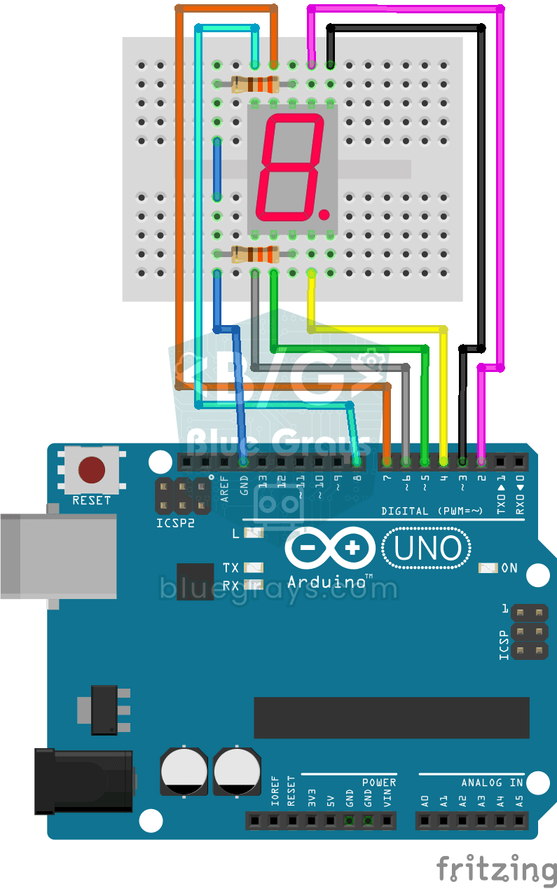
Displaying Numbers 0-9 on a 7-Segment Display
Write those familiar numbers you see in elevators and digital clocks yourself. On a display made of seven little light bars, the Arduino shows a digit from 0 to 9, one each second, and then starts…
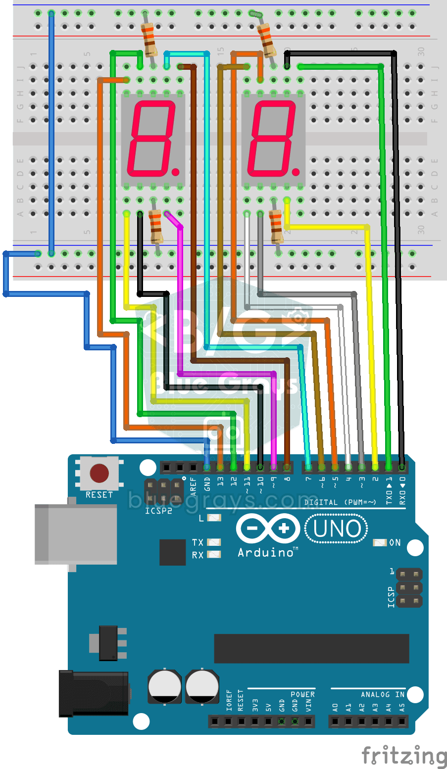
Displaying Numbers 0-99 on a 7-Segment Display
A two-digit display made of little bars, like the ones on a calculator, counts from 0 to 99.
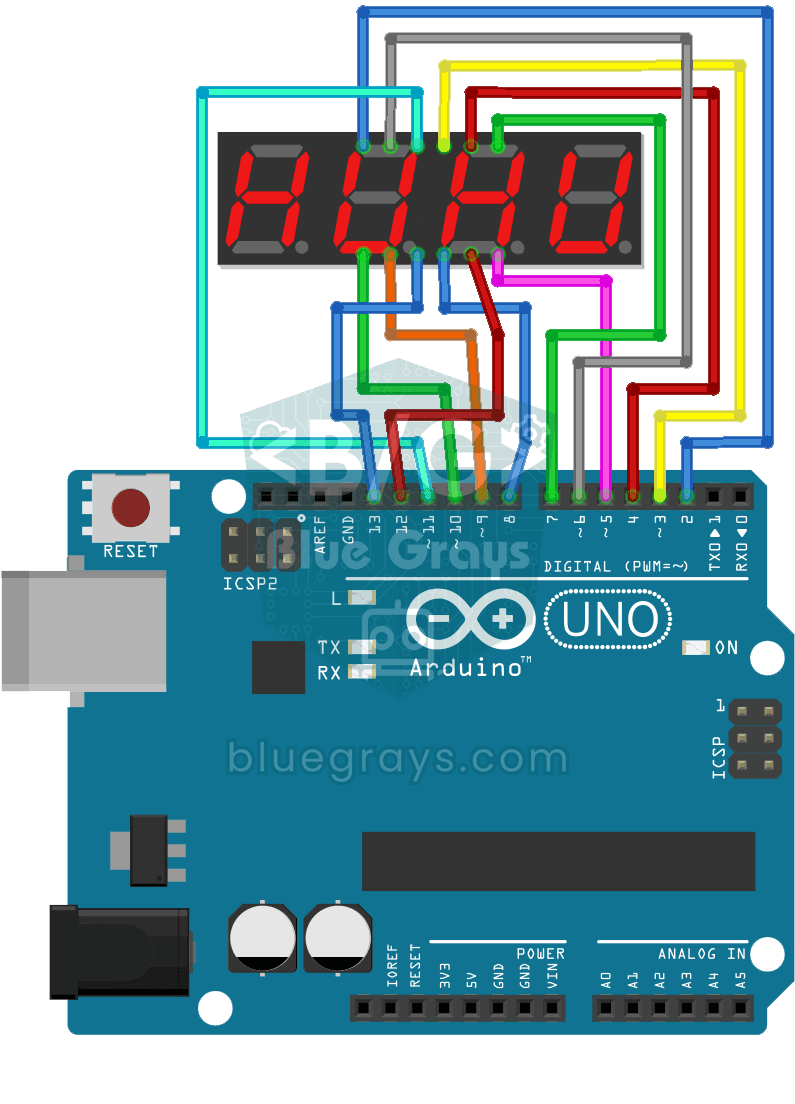
Displaying 0-9999 on a 4-Digit 7-Segment Display
On a four-digit number display, numbers race from 0 to 9999 and then start again from zero.
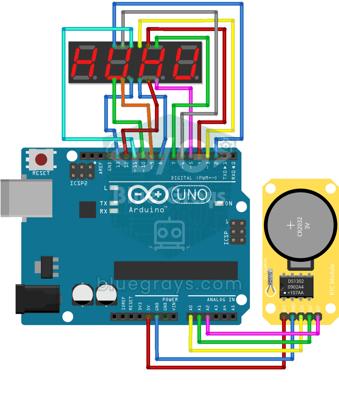
Digital Clock with 4-Digit 7-Segment Display
A four-digit glowing digital clock, much like the one on a kitchen oven. The DS1302 clock module keeps the time, and every second the Arduino reads the hours and minutes and shows them on the…

Dot Matrix Clock and Calendar (MAX7219, DS1307)
A glowing board for your desk or wall that shows the time and date in scrolling text.

Pixel Snake 8x8 Matrix
Build the classic snake game with your own hands and play it. On a colorful 8x8 light matrix, you steer a green snake with a joystick and eat red apples; with every apple the snake grows, speeds up a…