
Arduino Knight Rider LED Chaser: Circuit, Code and Speed Control
Build an Arduino Knight Rider LED chaser: 8 LEDs and 220 Ω wiring, array and for-loop code, pot speed control, millis, 74HC595, WS2812B, ESP32 and Pico.
The Arduino Knight Rider circuit is a classic LED effect in which a row of LEDs lights up one after another, sweeping from one end to the other and back again, named after the scanner light on the front of KITT, the talking car from the famous 1980s TV series. All you need is an Arduino Uno, 6 or 8 LEDs, a 220 Ω resistor for each LED and a few jumper wires. If the light only flows in one direction and then starts again from the beginning, it's called a running light or LED chaser. Both are classic projects that beginners build right after a traffic light, and they're the most fun way to learn two of the most important tools in programming: arrays and the for loop.
In this guide you'll build the circuit and write the running light code first, then the back-and-forth Knight Rider code. After that you'll set the speed with a potentiometer, add an effect where the LEDs stack up at one end, and run the same effect with millis() without ever blocking the code. In the last sections you'll find how to drive 8 LEDs from just 3 pins with a 74HC595 chip, how to build a Knight Rider with a fading tail from a single pin using WS2812B addressable LEDs, the ESP32 and Raspberry Pi Pico (MicroPython) versions, and fixes for the most common mistakes.
What is the Knight Rider effect, and how is it different from a running light?
In the series, the red light on KITT's front bumper sweeps left and right non-stop like a scanning eye. In electronics this effect is also called a Larson scanner, after the show's producer Glen A. Larson; the eyes of the Cylon robots in his other series, Battlestar Galactica, work the same way. On the real scanner you can see a slowly fading red trail, a tail, behind the lit spot. In a simple LED circuit each LED is either fully on or fully off; to imitate the tail you have to dim the LEDs gradually with PWM. We'll do exactly that later with the WS2812B and the ESP32. The table below summarises the effects you'll code in this article and how many steps one round takes with 8 LEDs.
| Effect | What it does | One round with 8 LEDs | In this article |
|---|---|---|---|
| Running light | A single light flows from left to right, then starts over | 8 steps | Step 1 |
| Knight Rider | A single light bounces between the two ends | 14 steps | Steps 2 and 3 |
| Stacking | Each light runs to the right-most free spot and stays there | 36 steps | Step 4 |
| Meet in the middle | Two lights come in from the ends to the middle, then move apart | 8 steps | 74HC595 section |
| Knight Rider with a tail | The head LED is at full brightness, the ones behind fade out | 14 steps | WS2812B and ESP32 sections |
Parts list and choosing the resistor
| Part | Qty | Note |
|---|---|---|
| Arduino Uno (or Nano) | 1 | An ESP32 or Raspberry Pi Pico works too |
| 5 mm LED | 6–8 | Same colour and same batch so they look equally bright |
| 220 Ω resistor | 6–8 | One per LED; 330 Ω on the Pico |
| 10 kΩ potentiometer (B10K) | 1 | Only for the speed-adjustable versions |
| Breadboard | 1 | Half size (400 holes) is enough |
| Jumper wires | 12–15 | Male to male |
| 74HC595 or an 8-LED WS2812B stick | 1 | Optional: for the pin-saving and tail-effect sections |
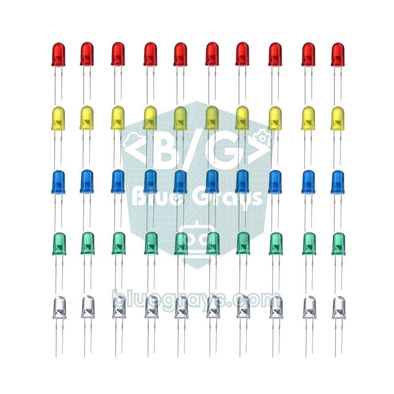
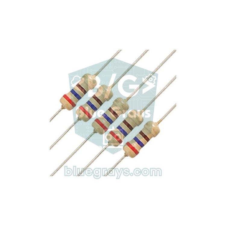
An LED doesn't limit its own current, so every LED gets a resistor in series. You find the value with Ohm's law: R = (supply voltage − LED forward voltage) / current. A red LED has a forward voltage of about 2 V, so at 5 V with 220 Ω the current is (5 − 2) / 220 ≈ 13.6 mA. That lights the LED nice and bright and stays below the 20 mA recommended for an Arduino pin. In the stacking effect, when all eight LEDs are on at the same time, the total current is about 109 mA, which is still within the Uno's 200 mA limit for all pins combined. To recognise a 220 Ω resistor by its colour bands, use the resistor colour code tool; for other colours and voltages, try the LED resistor calculator.
Wiring: 8 LEDs and a potentiometer
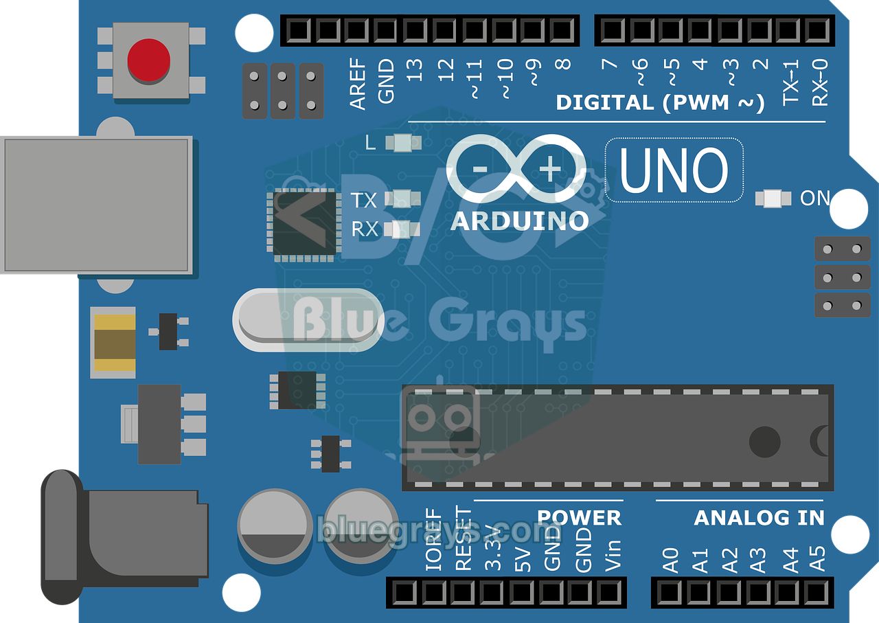
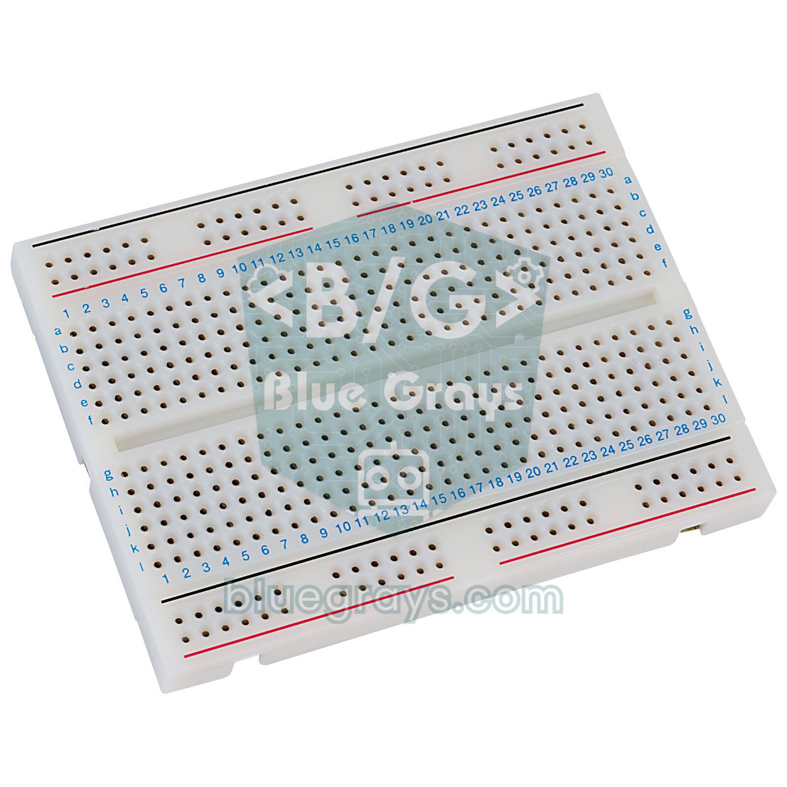
The long leg (anode) of each LED goes through a resistor to a digital pin on the board, and the short leg (cathode) goes to GND. On a breadboard the tidiest way is to connect the Arduino's GND pin to the blue (−) rail of the breadboard and bring the short legs of all eight LEDs to that rail. Place the LEDs at even spacing from left to right in pin order; that way the order in the code's array matches the physical order of the light. The potentiometer's two outer legs go to 5V and GND, and its middle leg (the wiper) goes to A0. The table below shows the pins used by every sketch in this article; if you're using 6 LEDs, skip the last two LED rows and delete the last two pins from the array in the code. You can see your board's pin layout in the Pinout tool.
| Function | Arduino Uno | ESP32 | Raspberry Pi Pico |
|---|---|---|---|
| LED 1 (far left) | D2 | GPIO 18 | GP8 |
| LED 2 | D3 | GPIO 19 | GP9 |
| LED 3 | D4 | GPIO 21 | GP10 |
| LED 4 | D5 | GPIO 22 | GP11 |
| LED 5 | D6 | GPIO 23 | GP12 |
| LED 6 | D7 | GPIO 25 | GP13 |
| LED 7 | D8 | GPIO 26 | GP14 |
| LED 8 (far right) | D9 | GPIO 27 | GP15 |
| Potentiometer middle leg | A0 | GPIO 34 | GP26 (ADC0) |
| Potentiometer outer legs | 5V and GND | 3V3 and GND | 3V3(OUT) and AGND |
| LED cathodes (short leg) | GND | GND | GND |
| Series resistor | 220 Ω | 220 Ω | 330 Ω |
Step 1: running light code with an array and a for loop
You could write eight separate pinMode lines and sixteen separate digitalWrite lines for eight LEDs, but the code gets long and changing the number of LEDs becomes a chore. Instead, you put the pin numbers into an array and walk through it with a for loop. The first element of the array is LEDS[0], which is D2; the last is LEDS[7], which is D9. This way the same code works unchanged with 6, 8 or 12 LEDs; you only edit the array. You'll find the basics of arrays and loops explained in more detail in Arduino programming basics.
1// Yürüyen LED: 8 LED sırayla yanar / Running light: 8 LEDs light up one after another
2const int LEDS[] = {2, 3, 4, 5, 6, 7, 8, 9};             // LED pinleri / LED pins
3const int LED_SAYISI = sizeof(LEDS) / sizeof(LEDS[0]);  // dizideki LED sayısı (8) / number of LEDs (8)
4const int BEKLE = 100;                                  // adım süresi (ms) / step time (ms)
5
6void setup() {
7  for (int i = 0; i < LED_SAYISI; i++) {
8    pinMode(LEDS[i], OUTPUT);                           // tüm LED pinleri çıkış / all LED pins as outputs
9  }
10}
11
12void loop() {
13  for (int i = 0; i < LED_SAYISI; i++) {
14    digitalWrite(LEDS[i], HIGH);                        // sıradaki LED'i yak / light the next LED
15    delay(BEKLE);
16    digitalWrite(LEDS[i], LOW);                         // söndür ve devam et / turn it off and move on
17  }
18}| Line | What it does |
|---|---|
| const int LEDS[] = {2, ..., 9}; | An array holding the LED pins in order from left to right; LEDS[0] = 2, LEDS[7] = 9 |
| sizeof(LEDS) / sizeof(LEDS[0]) | Works out the number of elements: on the Uno 16 bytes / 2 bytes = 8; it updates by itself when you add or remove pins |
| for (int i = 0; i < LED_SAYISI; i++) | Counts the variable i from 0 to 7; each round handles one element of the array |
| pinMode(LEDS[i], OUTPUT) | Makes all eight pins outputs with a single loop |
| digitalWrite, delay(BEKLE), digitalWrite | Turns the LED on, waits BEKLE milliseconds, turns it off and moves on to the next one |
With BEKLE (the step time) at 100 ms the light passes all eight LEDs in 0.8 seconds and starts again right away. Drop it to 30 ms and the flow becomes very fast; raise it to 300 ms and it looks slow, like lamps lighting one by one. To upload the code, select the board and port in the Tools menu and press Upload; if the upload fails, go through the checklist in Arduino code won't upload.
Step 2: Knight Rider (back-and-forth) code
For the Knight Rider effect, the light has to turn around when it reaches the right end. You do this with two loops: the first counts from left to right, the second from right to left. The subtle point here is the end LEDs. If both loops count all the way from 0 to 7 and from 7 to 0, the right-most LED lights once at the end of the forward loop and once again at the start of the backward loop; the light stays twice as long at the ends and the motion looks like it's stuttering. That's why the forward loop stops at 6 and the backward loop at 1. As a result each round takes exactly 14 steps and the light stays at the ends just as long as in the middle. We also moved the three lines that switch an LED on and off into a small function called yakSondur() ("light and turn off"); the code gets both shorter and easier to read.
1// Karaşimşek (Knight Rider): ışık iki uç arasında gidip gelir / light bounces between the two ends
2const int LEDS[] = {2, 3, 4, 5, 6, 7, 8, 9};
3const int LED_SAYISI = sizeof(LEDS) / sizeof(LEDS[0]);
4const int BEKLE = 80;                                   // adım süresi (ms) / step time (ms)
5
6void yakSondur(int i) {
7  digitalWrite(LEDS[i], HIGH);
8  delay(BEKLE);
9  digitalWrite(LEDS[i], LOW);
10}
11
12void setup() {
13  for (int i = 0; i < LED_SAYISI; i++) pinMode(LEDS[i], OUTPUT);
14}
15
16void loop() {
17  for (int i = 0; i < LED_SAYISI - 1; i++) {           // soldan sağa: 0..6 / left to right: 0..6
18    yakSondur(i);
19  }
20  for (int i = LED_SAYISI - 1; i > 0; i--) {           // sağdan sola: 7..1 / right to left: 7..1
21    yakSondur(i);
22  }
23}Step 3: speed control with a potentiometer
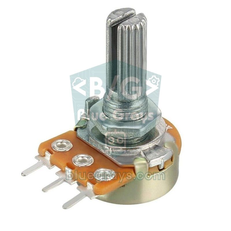
Instead of changing the code and uploading it again every time you want a different speed, you can use a potentiometer. A potentiometer is a voltage divider: the voltage on the middle leg changes between 0 and 5 V depending on the position of the shaft, and analogRead() turns it into a number between 0 and 1023. map(deger, 0, 1023, 400, 20) converts that number into a step time between 400 and 20 ms; because the range is written in reverse, the higher the reading, the shorter the step and the faster the light. Which way you have to turn the shaft to speed it up depends on which outer leg you connected to 5V; if it feels backwards, swap the two outer wires or swap 400 and 20 in map(). You can read about how a potentiometer works inside in What is a potentiometer?.
1// Hız ayarlı karaşimşek: potansiyometre adım süresini belirler / Speed-adjustable Knight Rider: the pot sets the step time
2const int LEDS[] = {2, 3, 4, 5, 6, 7, 8, 9};
3const int LED_SAYISI = sizeof(LEDS) / sizeof(LEDS[0]);
4const int POT = A0;                                     // potansiyometrenin orta bacağı / pot wiper
5
6int adimSuresi() {
7  int deger = analogRead(POT);                          // 0–1023
8  return map(deger, 0, 1023, 400, 20);                  // değer büyüdükçe hızlanır / faster as the value rises
9}
10
11void yakSondur(int i) {
12  digitalWrite(LEDS[i], HIGH);
13  delay(adimSuresi());                                  // her adımda yeniden okunur / read again on every step
14  digitalWrite(LEDS[i], LOW);
15}
16
17void setup() {
18  for (int i = 0; i < LED_SAYISI; i++) pinMode(LEDS[i], OUTPUT);
19}
20
21void loop() {
22  for (int i = 0; i < LED_SAYISI - 1; i++) yakSondur(i);   // sağa / to the right
23  for (int i = LED_SAYISI - 1; i > 0; i--) yakSondur(i);   // sola / to the left
24}
In this version the step time is read again for every LED, so the speed changes the moment you turn the shaft. However, while delay() is running the Arduino can't do anything else: even if you turn the shaft in the middle of a slow 400 ms step, the new speed only applies from the next step. For an effect with a few LEDs that's no problem, but once you add a mode button or sensor readings you need to switch to the millis() method from step 5.
Step 4: the stacking effect
In the stacking effect the first light runs all the way to the right and stays lit at the far right. The second light runs too, but this time it stops one place further left; each round the target moves one LED to the left until the whole bar is full. In code you do this with two nested loops: the outer loop counts how many LEDs have stacked up (dolu, "full"), and the inner loop counts how many steps the light runs in this round. The LED that reaches its target (hedef) isn't switched off; the line if (i < hedef) takes care of exactly that. With eight LEDs, filling the whole bar takes 8 + 7 + 6 + ... + 1 = 36 steps.
1// Birikerek dolan efekt: her ışık en boş uca kadar gider ve orada kalır / Stacking effect: each light runs to the last free spot and stays
2const int LEDS[] = {2, 3, 4, 5, 6, 7, 8, 9};
3const int LED_SAYISI = sizeof(LEDS) / sizeof(LEDS[0]);
4const int BEKLE = 60;
5
6void setup() {
7  for (int i = 0; i < LED_SAYISI; i++) pinMode(LEDS[i], OUTPUT);
8}
9
10void loop() {
11  for (int dolu = 0; dolu < LED_SAYISI; dolu++) {       // dolu: sağda birikmiş LED sayısı / LEDs already stacked on the right
12    int hedef = LED_SAYISI - 1 - dolu;                  // bu turda ışığın duracağı yer / where the light stops this round
13    for (int i = 0; i <= hedef; i++) {
14      digitalWrite(LEDS[i], HIGH);
15      delay(BEKLE);
16      if (i < hedef) digitalWrite(LEDS[i], LOW);        // hedefte yanık kalır / stays lit at the target
17    }
18  }
19  delay(600);                                           // dolu çubuğu göster / show the full bar
20  for (int i = LED_SAYISI - 1; i >= 0; i--) {           // sağdan sola boşalt / empty from right to left
21    digitalWrite(LEDS[i], LOW);
22    delay(BEKLE);
23  }
24  delay(300);
25}
At the end of the sketch the full bar is shown for 0.6 seconds, then the LEDs go out one by one from right to left and the effect starts over. If you want a simpler filling bar, just remove the inner loop and switch the LEDs on in order without ever turning them off; that look is ideal for a charge indicator or a sound level bar. Remember that all eight LEDs are on at the same time in this effect: as long as each LED has its own resistor, the brightness won't drop.
Step 5: non-blocking Knight Rider with millis()
In code that uses delay(), the Arduino freezes for the given time on every step; even if someone presses a button meanwhile, it won't notice. millis(), on the other hand, returns the time in milliseconds since the board was switched on. The logic goes like this: the loop runs constantly, checks every time round whether enough time has passed since the last step, takes just one step if it has, and leaves again immediately. In the code below the Knight Rider and the onboard LED run at the same time as two independent tasks: while the scanner sweeps at the speed set by the potentiometer, the LED on D13 blinks once a second at its own pace. For more on this topic, see Arduino millis() vs delay().
1// millis() ile bekletmesiz karaşimşek + potansiyometre / Non-blocking Knight Rider with millis() + pot
2const int LEDS[] = {2, 3, 4, 5, 6, 7, 8, 9};
3const int LED_SAYISI = sizeof(LEDS) / sizeof(LEDS[0]);
4const int POT = A0;
5
6int konum = 0;                     // şu an yanan LED / the LED that is lit now
7int yon = 1;                       // +1 sağa, -1 sola / +1 right, -1 left
8unsigned long sonAdim = 0;         // son adımın zamanı / time of the last step
9unsigned long sonBlink = 0;        // dahili LED için / for the onboard LED
10
11void setup() {
12  for (int i = 0; i < LED_SAYISI; i++) pinMode(LEDS[i], OUTPUT);
13  pinMode(LED_BUILTIN, OUTPUT);    // Uno'da D13 / D13 on the Uno
14  digitalWrite(LEDS[konum], HIGH);
15}
16
17void loop() {
18  unsigned long simdi = millis();
19  unsigned long aralik = map(analogRead(POT), 0, 1023, 400, 20);   // adım süresi (ms) / step time (ms)
20
21  // Görev 1: karaşimşek / Task 1: Knight Rider
22  if (simdi - sonAdim >= aralik) {          // taşmaya karşı güvenli / overflow-safe
23    sonAdim = simdi;
24    digitalWrite(LEDS[konum], LOW);
25    konum += yon;
26    if (konum == LED_SAYISI - 1 || konum == 0) yon = -yon;   // uçta yön değiştir / reverse at the ends
27    digitalWrite(LEDS[konum], HIGH);
28  }
29
30  // Görev 2: dahili LED kendi temposunda yanıp söner / Task 2: the onboard LED blinks at its own pace
31  if (simdi - sonBlink >= 500) {
32    sonBlink = simdi;
33    digitalWrite(LED_BUILTIN, !digitalRead(LED_BUILTIN));
34  }
35  // Buraya buton, sensör ya da seri port kodu eklenebilir / button, sensor or serial code can go here
36}
Two details matter here. First, the time variables must be unsigned long; if you use int, the value overflows on the Uno after about 32.7 seconds and the timing breaks: the effect either stops or speeds up out of control. Second, the comparison is done with a subtraction in the form simdi - sonAdim >= aralik (now minus last step, compared with the interval); this method keeps working correctly even when millis() rolls over to zero roughly every 49.7 days. Because we keep the light's position and direction in two variables (konum and yon), there are no loops any more: on every step the position goes up or down by one, and at the ends the direction changes sign.
8 LEDs from 3 pins with a 74HC595
Eight LEDs take up eight of the Uno's pins; once you want to add an LCD, sensors and buttons to your project, you start running out. The 74HC595 shift register drives its eight outputs from just three Arduino pins (data, clock and latch). The state of each LED is one bit of a byte: the expression 1 << i sets only bit i to 1, which lights a single LED. Building patterns with bit operations is easy too: (1 << i) | (0x80 >> i) produces two lights coming in from both ends towards the middle at the same time. By chaining two chips you can also build a 16-LED Knight Rider with the same three pins; chaining, fast driving over SPI and using 7-segment displays are explained step by step in the 74HC595 shift register article.
| 74HC595 pin | Connection (Arduino Uno) |
|---|---|
| DS (14) | D11 |
| SH_CP (11) | D13 |
| ST_CP (12) | D10 |
| OE (13) | GND (outputs always enabled) |
| MR (10) | 5V (reset disabled) |
| VCC (16) / GND (8) | 5V / GND, with a 100 nF capacitor next to it |
| Q0 (15), Q1–Q7 (1–7) | Each one through 470 Ω to the anode of an LED |
| Potentiometer middle leg | A0 |
1// 74HC595 ile 3 pinden 8 LED: karaşimşek ve ortada buluşma / 8 LEDs from 3 pins with a 74HC595: Knight Rider and meet-in-the-middle
2const int DATA_PIN = 11;    // DS (14)
3const int CLOCK_PIN = 13;   // SH_CP (11)
4const int LATCH_PIN = 10;   // ST_CP (12)
5const int POT = A0;
6
7void yaz595(byte desen) {
8  digitalWrite(LATCH_PIN, LOW);
9  shiftOut(DATA_PIN, CLOCK_PIN, MSBFIRST, desen);   // 8 biti gönder / send the 8 bits
10  digitalWrite(LATCH_PIN, HIGH);                    // çıkışlara aktar / copy to the outputs
11}
12
13void setup() {
14  pinMode(DATA_PIN, OUTPUT);
15  pinMode(CLOCK_PIN, OUTPUT);
16  pinMode(LATCH_PIN, OUTPUT);
17  yaz595(0);                                        // açılışta hepsi sönük / all off at startup
18}
19
20void loop() {
21  int bekle = map(analogRead(POT), 0, 1023, 400, 20);
22
23  for (int i = 0; i < 7; i++) { yaz595(1 << i); delay(bekle); }   // Q0 -> Q7
24  for (int i = 7; i > 0; i--) { yaz595(1 << i); delay(bekle); }   // Q7 -> Q0
25
26  for (int i = 0; i < 4; i++) {                     // uçlardan ortaya / from the ends to the middle
27    yaz595((1 << i) | (0x80 >> i));
28    delay(bekle);
29  }
30  for (int i = 3; i >= 0; i--) {                    // ortadan uçlara / from the middle to the ends
31    yaz595((1 << i) | (0x80 >> i));
32    delay(bekle);
33  }
34}
On the 74HC595 outputs 470 Ω is recommended instead of 220 Ω: the total current through the chip's VCC and GND pins shouldn't exceed 70 mA. With 470 Ω about 6.4 mA flows per LED, and even with all eight LEDs on the total stays at 51 mA. In a Knight Rider only one or two LEDs are on at a time anyway, so the LEDs are still clearly visible.
Knight Rider with a fading tail from a single pin with WS2812B
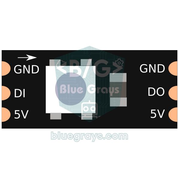
The version that looks most like the real KITT scanner is built with WS2812B addressable LEDs. Each WS2812B has its own driver built in; however long the strip is, you set the colour and brightness of each LED individually over a single data wire. For the tail we keep an array: on every step the brightness of all LEDs is divided by three, and the head LED is set to 255. The LEDs behind it fade quickly through 255, 85, 28, 9, leaving a natural trail behind the light. Use 2 instead of 3 as the divisor and the tail gets longer; use 5 and it gets shorter. To go from 8 to 60 LEDs with the same method, you only need to change NUM_LEDS.
1// WS2812B ile kuyruklu karaşimşek (tek veri pini) / Knight Rider with a fading tail on WS2812B (one data pin)
2#include <Adafruit_NeoPixel.h>
3
4const int DATA_PIN = 6;      // DIN, 330 Ω üzerinden / DIN through 330 Ω
5const int NUM_LEDS = 8;      // şerit ya da çubuktaki LED sayısı / LEDs on the strip or stick
6const int POT = A0;
7
8Adafruit_NeoPixel strip(NUM_LEDS, DATA_PIN, NEO_GRB + NEO_KHZ800);
9
10uint8_t seviye[NUM_LEDS];    // her LED'in kırmızı parlaklığı / red brightness of each LED
11int konum = 0;
12int yon = 1;
13
14void setup() {
15  strip.begin();
16  strip.setBrightness(80);   // 0–255; USB için düşük tut / keep it low on USB power
17  strip.show();              // hepsini söndür / all off
18}
19
20void loop() {
21  for (int i = 0; i < NUM_LEDS; i++) seviye[i] = seviye[i] / 3;   // kuyruk söner / the tail fades
22  seviye[konum] = 255;                                            // baştaki LED tam parlak / the head is full brightness
23
24  for (int i = 0; i < NUM_LEDS; i++) {
25    strip.setPixelColor(i, strip.Color(seviye[i], 0, 0));         // yalnız kırmızı / red only
26  }
27  strip.show();
28
29  konum += yon;
30  if (konum == NUM_LEDS - 1 || konum == 0) yon = -yon;            // uçta yön değiştir / reverse at the ends
31  delay(map(analogRead(POT), 0, 1023, 150, 20));
32}Knight Rider on the ESP32: a PWM tail on every pin
On the Uno a Knight Rider with a tail is hard to build with ordinary LEDs, because PWM is only available on pins 3, 5, 6, 9, 10 and 11, and our D2–D9 array contains only four of them. On the ESP32, thanks to the LEDC hardware, almost every output pin can generate PWM, and the classic ESP32 has 16 PWM channels. Since analogWrite() works directly in the current ESP32 Arduino core, you can apply the WS2812B tail logic to ordinary LEDs. The pins in the table are safe GPIOs that don't affect booting; the potentiometer connects to GPIO 34 on the ADC1 channel, which reads reliably even with Wi-Fi on, and because the ESP32's ADC is 12-bit the value ranges from 0 to 4095. The ESP32's pins output 3.3 V, so about 6 mA flows through a red LED with 220 Ω; the LEDs look a little dimmer than on the Uno. For setting up the board, see What is the ESP32?.
1// ESP32: her pinde PWM ile kuyruklu karaşimşek / ESP32: Knight Rider with a PWM tail on every pin
2const int LEDS[] = {18, 19, 21, 22, 23, 25, 26, 27};
3const int LED_SAYISI = sizeof(LEDS) / sizeof(LEDS[0]);
4const int POT = 34;                        // ADC1, yalnızca giriş / ADC1, input only
5
6int parlaklik[LED_SAYISI];                 // 0–255
7int konum = 0;
8int yon = 1;
9unsigned long sonAdim = 0;
10
11void setup() {
12  // analogWrite() pini PWM için kendisi hazırlar / analogWrite() sets the pin up for PWM itself
13}
14
15void loop() {
16  unsigned long aralik = map(analogRead(POT), 0, 4095, 400, 20);   // ESP32 ADC 12 bit: 0–4095
17  if (millis() - sonAdim >= aralik) {
18    sonAdim = millis();
19    for (int i = 0; i < LED_SAYISI; i++) parlaklik[i] /= 3;        // kuyruk söner / the tail fades
20    parlaklik[konum] = 255;
21    for (int i = 0; i < LED_SAYISI; i++) analogWrite(LEDS[i], parlaklik[i]);
22    konum += yon;
23    if (konum == LED_SAYISI - 1 || konum == 0) yon = -yon;
24  }
25}
Knight Rider on the Raspberry Pi Pico with MicroPython
On the Raspberry Pi Pico you can write the same effect in a few lines of MicroPython. Keeping the Pin objects in a list does the same job as the array on the Arduino. time.ticks_ms() and time.ticks_diff() are the MicroPython equivalents of millis() and the overflow-safe subtraction. The potentiometer connects to GP26 (ADC0); read_u16() returns a value from 0 to 65535 and the code converts it to 400–20 ms. It's recommended that the total current drawn from all of the Pico's GPIOs stays below 50 mA; that's why we chose 330 Ω in the table: about 4 mA flows per LED, and even with all eight LEDs on the total stays around 32 mA. The BlueGrays Pico Knight Rider project uses 6 LEDs on pins GP9–GP14; if you've built that circuit, just change the PINLER list to [9, 10, 11, 12, 13, 14]. For setup and uploading code with Thonny, see What is the Raspberry Pi Pico?.
1# Raspberry Pi Pico: potansiyometreyle hız ayarlı karaşimşek / Pico: Knight Rider with pot speed control
2from machine import Pin, ADC
3import time
4
5PINLER = [8, 9, 10, 11, 12, 13, 14, 15]        # GP8–GP15
6leds = [Pin(p, Pin.OUT) for p in PINLER]
7pot = ADC(26)                                   # GP26 = ADC0
8
9def adim_suresi():
10    # read_u16: 0–65535 -> 400–20 ms
11    return 400 - pot.read_u16() * 380 // 65535
12
13konum, yon = 0, 1
14leds[konum].on()
15son = time.ticks_ms()
16
17while True:
18    if time.ticks_diff(time.ticks_ms(), son) >= adim_suresi():   # millis() benzeri / like millis()
19        son = time.ticks_ms()
20        leds[konum].off()
21        konum += yon
22        if konum == len(leds) - 1 or konum == 0:
23            yon = -yon                          # uçta yön değiştir / reverse at the ends
24        leds[konum].on()
Every GPIO on the Pico can generate PWM as well; with machine.PWM and a duty_u16() value for each LED you can bring the ESP32's tail effect over to the Pico. If you want to use WS2812B LEDs, MicroPython's built-in neopixel module drives a strip from a single GPIO; however, a WS2812B powered at 5 V doesn't always read the Pico's 3.3 V data signal reliably, so if the colours glitch, add a level shifter in between.
Knight Rider project ideas
- Sound level meter (VU meter): use the loudness measured with a KY-038 sound sensor to decide how many LEDs of the filling bar light up.
- Parking sensor LED bar: light more LEDs as the distance measured with an HC-SR04 shrinks, and flash them all when you get very close.
- Catch-the-light game: while the scanner sweeps quickly, try to press a button exactly when the middle LED is lit; make the step time shorter after every success.
- Automatic night-time decoration: start the effect by itself when an LDR detects that it's getting dark.
- Rear light for a model car or bike: make a red Knight Rider with a tail on a WS2812B stick, and light all LEDs at full brightness when the brake button is pressed.
- Level indicator: show the position of a potentiometer or a battery voltage as a filling bar.
- Bigger displays: take the same logic to a MAX7219 LED matrix or an LED cube.
Common mistakes and how to fix them
| Symptom | Cause | Fix |
|---|---|---|
| The LEDs are very dim | pinMode(OUTPUT) is missing; digitalWrite only switches on the internal pull-up resistor | Make all pins OUTPUT with a loop in setup() |
| One LED never lights | The LED is reversed, or a resistor or wire is one row off | Long leg to the resistor and pin, short leg to GND; test the LED on its own with 5V and a resistor |
| The end LEDs stay lit twice as long | Both loops include the end LEDs | Use i < LED_SAYISI − 1 in the forward loop and i > 0 in the backward loop |
| A random pin flickers or the program acts strangely | Reading past the end of the array: i <= LED_SAYISI | Change the condition to i < LED_SAYISI; there is no element LEDS[8] |
| The code won't upload, or the LEDs flicker during upload | LEDs are connected to D0 and D1 | Start the array at D2 |
| The potentiometer doesn't change the speed | An outer leg is connected to A0 instead of the middle leg, or the value is read only once outside the loop | Connect the middle leg to A0; call analogRead on every step |
| The effect goes wrong after about 32 seconds | The millis() value is stored in an int variable | Make the time variables unsigned long |
| The WS2812Bs don't light at all or show random colours | No common GND, no data resistor, or the strip is connected at the wrong end (DOUT) | Join the GNDs, add 330 Ω, connect to the DIN end the arrows point away from |
The Knight Rider looks simple, but it contains the basic ideas you'll use in every project later on: arrays, loops, analog readings, map(), non-blocking timing, bit operations and addressable LEDs. For your next step, take a look at the Arduino traffic light project or the list of Arduino project ideas. In the BlueGrays app you'll find the running light, Knight Rider and speed-adjustable versions, WS2812B stacking and Knight Rider effects, and the ESP32 running light and Pico Knight Rider projects, each with a step-by-step circuit diagram and ready-to-use code to try on your own board.
Frequently asked questions
How many LEDs can an Arduino Uno control?
The Uno has 20 pins that can be used as digital outputs, D0–D13 and A0–A5; if you leave D0 and D1 free for serial communication, you can drive 18 LEDs directly. Give each LED its own resistor and keep the total current below 200 mA; if all 18 will be on at once, choose 330 Ω or more. For more LEDs, use a 74HC595 shift register or a WS2812B strip, which drives hundreds of LEDs from one pin.
What resistor do I need for an LED chaser?
On a 5 V Arduino Uno, 220 Ω suits red LEDs and gives about 13.6 mA per LED; 330 Ω works too, but the LEDs are a little dimmer. On the 3.3 V ESP32 220 Ω is recommended, and 330 Ω on the Pico. In effects where only one LED is on, a single shared resistor also works, but the brightness drops when several LEDs light up, so one resistor per LED is the right choice.
Can you build a Knight Rider circuit without an Arduino?
Yes, the classic way is a 555 timer and a CD4017 counter chip. The 555 produces clock pulses and the 4017 sets its 10 outputs HIGH one after another, which on its own gives a running light. For the back-and-forth motion the outputs are combined with diodes: the 10 outputs are connected to 6 LEDs in the order 1-2-3-4-5-6-5-4-3-2, and the speed is set with a potentiometer on the 555.
What is the difference between a running light and a Knight Rider effect?
In a running light the light flows in one direction and starts again after the last LED; with 8 LEDs one round is 8 steps. In a Knight Rider the light turns around at the end and bounces between the two ends; with 8 LEDs one round is 14 steps. The difference in code is small too: for the Knight Rider you add a second loop that counts backwards.
Why use millis() instead of delay() for an LED chaser?
While delay() is running the Arduino can't do anything else; it misses button presses and can't read sensors. With millis(), each pass of the loop takes a step only when the time is up, and other tasks run in the remaining time. So while the scanner sweeps, buttons, potentiometers or serial commands respond instantly.
How do you add a fading tail to the Knight Rider effect?
For the tail you need to dim the LEDs behind the head gradually, which requires PWM. On the Uno PWM is only available on pins 3, 5, 6, 9, 10 and 11, so you can build a 6-LED Knight Rider with a tail on those pins. The easier route is a WS2812B strip, where you set every LED individually, or an ESP32 or Pico, which have PWM on every pin.
Projects to build after reading this
See all projects
Knight Rider LED Effect
The classic scanner light: a dot of light slides from one end of six LEDs to the other and then comes back. The Arduino lights each LED for a tenth of a second before moving on, turns around at each e

LED Chaser
Lights that switch on one after another, as if they were running. The Arduino lights six LEDs one at a time; each glows for a brief moment and goes out, so the light walks from start to end and then s

Knight Rider LED Effect with Adjustable Speed
A light runs from one end of six LEDs to the other, turns around and runs back again. Turn the potentiometer knob and you change the speed of that run instantly: with the knob at one end the light alm

LED Chaser with Adjustable Speed
Six LEDs light up one after another, so the light seems to run from one end to the other. Turn the potentiometer knob and the speed of that run changes instantly: one way and the light races along, th
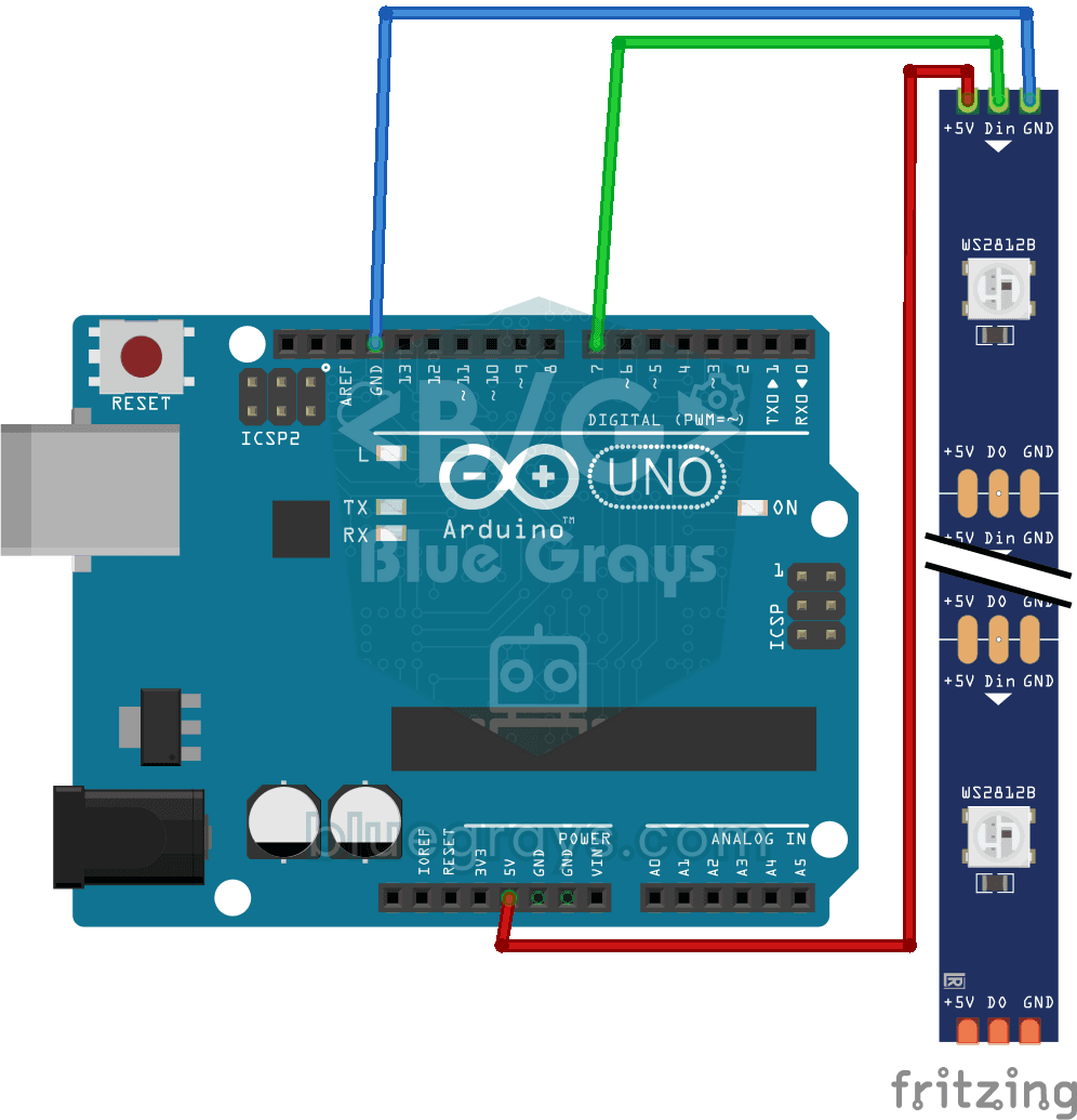
WS2812B Knight Rider Effect
A red dot of light slides from one end of a smart LED strip to the other, then comes back, sweeping back and forth without ever stopping. At each step the Arduino lights just one LED, waits a tenth of
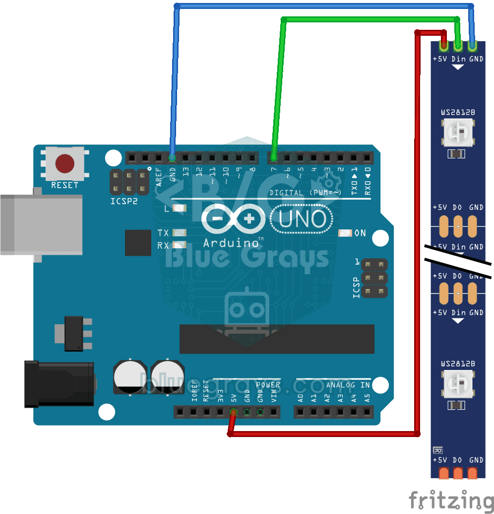
WS2812B LED Chaser (Fill Effect)
A light strip that fills up and empties like a glass of water. The Arduino lights ten color LEDs one by one in orange and keeps them on; once the strip is full, it switches them off one by one in the

ESP32 Knight Rider LED
6 LEDs moving sequentially from left to right and right to left (Knight Rider style). A basic example of using for loops and arrays. Teaches the logic of direction change.
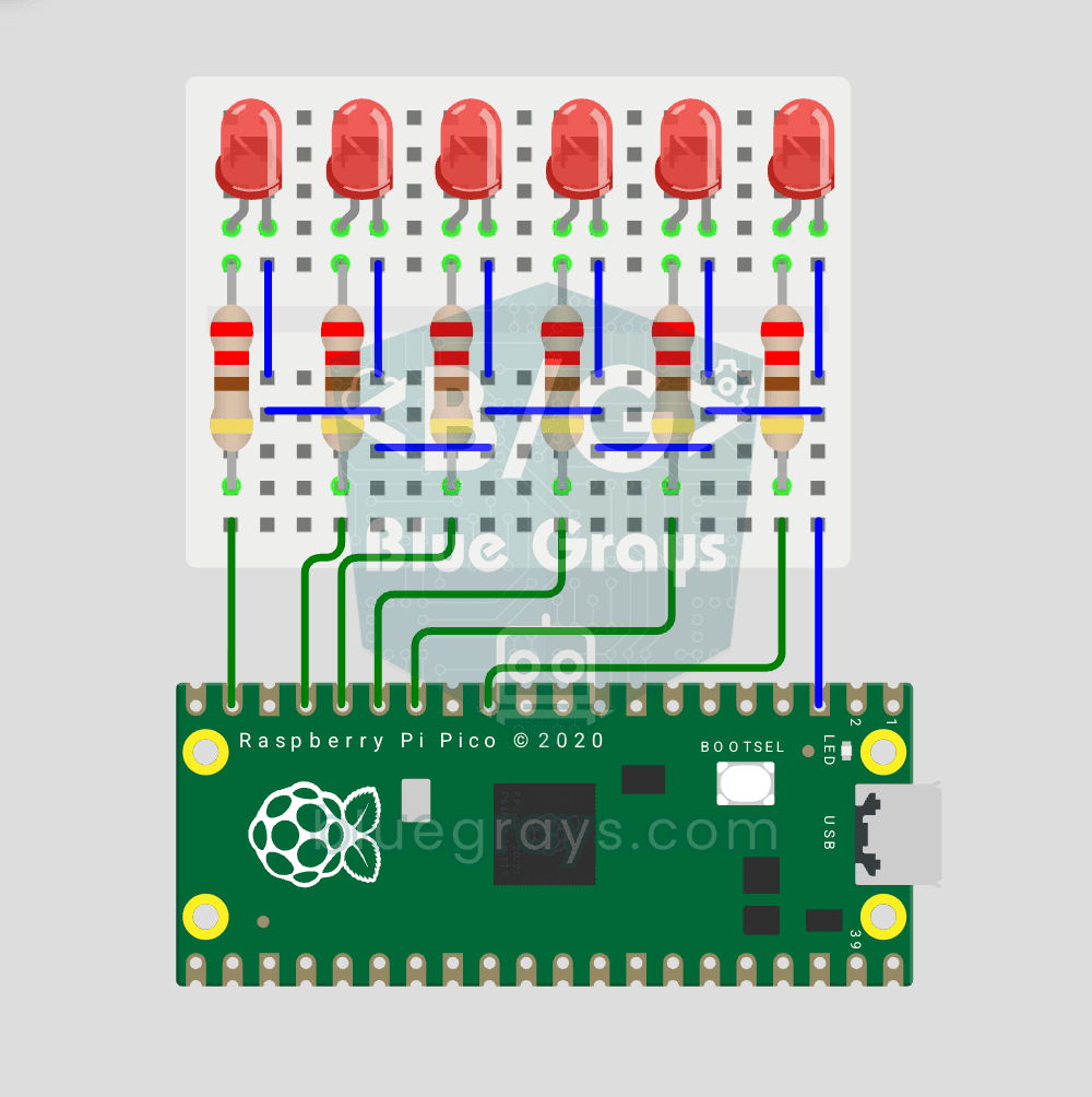
Raspberry Pi Pico Knight Rider LED Scanner (6 LED Back-Forth)
Classic "Knight Rider" LED scanner effect with Pico! 6 LEDs go left-to-right, then right-to-left, forever. Like the front grille of KITT car from the iconic 80s TV series. This project is an upgrade of the Chasing LED project: same 6 LED circuit (GP9-GP14), different code pattern. Learn reversed() function for list reversal, two separate for loops for back-and-forth pattern, and generating multiple animations on same circuit.