
PCF8574 Arduino: I2C I/O Expander for 8 Extra Pins, with Code
PCF8574 Arduino guide: 8 extra I/O pins over I2C, A0-A2 address table, wiring LEDs and buttons, INT interrupt, the I2C LCD backpack and MCP23017 comparison.

The PCF8574 is a cheap I2C I/O expander that gives your Arduino 8 extra input/output pins over just two wires (SDA and SCL). Using a PCF8574 with Arduino pays off whenever you run out of pins: when an LCD, a sensor and a few relays have already taken most of them, the PCF8574 simply joins the same I2C bus and hands you 8 more pins for buttons and LEDs. With the A0, A1 and A2 address pins you can put up to 8 modules on one bus and reach 64 extra pins.
In this guide you will learn about the PCF8574's quasi-bidirectional pins, why that makes LEDs light up when you write LOW, and how to read buttons. You will get the address table (PCF8574 and PCF8574A), read buttons through the INT pin with an interrupt, discover that the I2C LCD backpack you use every day is really a PCF8574, and see how it compares with the MCP23017. The code is ready for Arduino Uno, ESP32 and Raspberry Pi Pico (MicroPython).
What is the PCF8574 and how does it work?
Inside the PCF8574 is an 8-bit output latch. The Arduino sends a single byte over I2C and each bit sets the state of one pin: P0 is the least significant bit, P7 the most significant. The pins do not behave like classic push-pull outputs. When LOW, a pin is tied to GND through a strong switch and can sink up to 25 mA. When HIGH, it is held up only by a weak current source of about 100 µA. This is called a quasi-bidirectional design, and it has two important consequences: wire LEDs so the pin sinks the current (anode to VCC), and write a 1 to a pin before using it as an input. When a button pulls that HIGH pin to GND, you read a 0. At power-up all pins are HIGH.
| Feature | Value |
|---|---|
| Pins | 8 (P0–P7), quasi-bidirectional |
| Supply | 2.5–6 V (works at 3.3 V and 5 V) |
| Interface | I2C, up to 100 kHz |
| Address | PCF8574: 0x20–0x27, PCF8574A: 0x38–0x3F |
| LOW output current | Up to 25 mA per pin (sink) |
| HIGH output current | About 100 µA (weak pull-up) |
| Interrupt | INT pin, open-drain, active LOW |
| Package | DIP-16 (PCF8574P) and SO-16 (PCF8574T) |
PCF8574 pinout and wiring
| PCF8574 / module | Arduino Uno | ESP32 | Raspberry Pi Pico |
|---|---|---|---|
| VCC | 5V | 3V3 | 3V3 (OUT) |
| GND | GND | GND | GND |
| SDA | A4 | GPIO 21 | GP4 |
| SCL | A5 | GPIO 22 | GP5 |
| INT (optional) | D2 | GPIO 4 | GP6 |
| P0–P3 | LEDs: anode to VCC through a resistor, cathode to the pin | Same | Same |
| P4–P7 | Buttons: one leg to the pin, the other to GND | Same | Same |
In the examples, four LEDs sit on P0–P3 and four buttons on P4–P7. Each LED's anode goes to VCC through a 330 Ω resistor and its cathode to the PCF8574 pin; when you write 0 to the pin, current flows through the LED into the pin and the LED lights up. At 5 V, 330 Ω means (5 - 2) / 330 ≈ 9 mA for a red LED; pick the right value for your LED with the LED resistor calculator. The buttons need no resistor of their own, because the chip's weak current source acts as a pull-up. On long breadboard wires an external 10 kΩ pull-up still helps against noise; the basics are in pull-up and pull-down resistors. If you use the bare chip in a DIP-16 package, pins 1–3 are A0–A2, 4–7 and 9–12 are P0–P7, 8 is GND, 13 INT, 14 SCL, 15 SDA and 16 VCC.
Setting the address: A0, A1, A2 and the PCF8574A
| A2 | A1 | A0 | PCF8574 | PCF8574A |
|---|---|---|---|---|
| 0 | 0 | 0 | 0x20 | 0x38 |
| 0 | 0 | 1 | 0x21 | 0x39 |
| 0 | 1 | 0 | 0x22 | 0x3A |
| 0 | 1 | 1 | 0x23 | 0x3B |
| 1 | 0 | 0 | 0x24 | 0x3C |
| 1 | 0 | 1 | 0x25 | 0x3D |
| 1 | 1 | 0 | 0x26 | 0x3E |
| 1 | 1 | 1 | 0x27 | 0x3F |
The address depends on whether A0–A2 are tied to GND or VCC; in the table 1 means VCC and 0 means GND. The common purple expander boards have jumpers or small DIP switches for these three pins, usually set to 0x20 out of the box. Eight modules of the same type give you 64 pins, and mixing the PCF8574 with the PCF8574A gets you 16 modules and 128 pins. If you are not sure about the address, run the I2C scanner from what is I2C or the I2C LCD display guide; if the chip marking contains an "A", the address range is 0x38–0x3F.
First sketch without a library: reading buttons and driving LEDs
1// PCF8574: P0-P3 LED (LOW = yanar), P4-P7 düğme (GND'ye) / P0-P3 LEDs (LOW = on), P4-P7 buttons (to GND)
2#include <Wire.h>
3
4const uint8_t PCF_ADDR = 0x20;           // A0, A1, A2 = GND
5uint8_t lastButtons = 0x0F;
6
7void pcfWrite(uint8_t value) {
8  Wire.beginTransmission(PCF_ADDR);
9  Wire.write(value);                     // 8 pinin hepsi tek baytta / all 8 pins in one byte
10  Wire.endTransmission();
11}
12
13uint8_t pcfRead() {
14  Wire.requestFrom(PCF_ADDR, (uint8_t)1);
15  return Wire.available() ? Wire.read() : 0xFF;
16}
17
18void setup() {
19  Serial.begin(9600);
20  Wire.begin();                          // Uno: SDA = A4, SCL = A5
21  pcfWrite(0xFF);                        // hepsi HIGH: LED'ler sönük, girişler hazır / all HIGH: LEDs off, inputs ready
22}
23
24void loop() {
25  uint8_t buttons = pcfRead() >> 4;      // P4-P7, basılı = 0 / pressed = 0
26  // Üst 4 bit 1 kalmalı (giriş); basılı düğme kendi LED'ini yakar
27  // Upper 4 bits must stay 1 (inputs); a pressed button lights its LED
28  pcfWrite(0xF0 | buttons);
29  if (buttons != lastButtons) {
30    lastButtons = buttons;
31    Serial.print("Buttons P7..P4: ");
32    Serial.println(buttons | 0x10, BIN); // baştaki 1 sıfırları göstermek için / leading 1 keeps the zeros visible
33  }
34  delay(20);
35}
You do not even need a library to talk to a PCF8574: one byte sent with Wire.write() sets all 8 pins at once, and one byte read with Wire.requestFrom() returns the current state of all 8 pins. Shifting the byte 4 bits to the right moves the buttons on P4–P7 into the lower four bits, and a pressed button reads as 0. When writing, 0xF0 | buttons does two jobs: it keeps the upper four bits at 1 so P4–P7 stay inputs, and it copies the button states into the lower four bits. Because a pressed button's bit is 0, the matching LED pin goes LOW and the LED lights. If bit operations are new to you, number systems and bit operations is a good place to start.
The INT pin: reading buttons with an interrupt instead of polling
The sketch above keeps the I2C bus busy dozens of times per second. The PCF8574's INT pin goes LOW as soon as any input has changed since the last read and stays there until the chip is read or written. Connect it to an Arduino interrupt pin and you only read when something changes; the rest of the time the bus and the processor stay available for other work. The next example uses Rob Tillaart's PCF8574 library, which you can install from the Library Manager. From version 0.4 of the library on, you have to call Wire.begin() yourself before pcf.begin().
1// PCF8574 + INT pini: yalnız değişiklik olunca oku / read only when something changes
2#include <Wire.h>
3#include <PCF8574.h>                     // Rob Tillaart
4
5#ifndef IRAM_ATTR
6#define IRAM_ATTR                        // AVR'de boş / empty on AVR
7#endif
8
9#if defined(ESP32)
10const int INT_PIN = 4;                   // PCF8574 INT -> GPIO 4
11#else
12const int INT_PIN = 2;                   // PCF8574 INT -> D2 (Uno kesme pini / Uno interrupt pin)
13#endif
14
15PCF8574 pcf(0x20);
16volatile bool changed = false;
17uint8_t lastState = 0xFF;
18
19void IRAM_ATTR onPcfInt() {
20  changed = true;                        // yalnız bayrak kaldır / just raise a flag
21}
22
23void setup() {
24  Serial.begin(115200);
25#if defined(ESP32)
26  Wire.begin(21, 22);                    // SDA, SCL
27#else
28  Wire.begin();
29#endif
30  if (!pcf.begin(0xFF)) Serial.println("PCF8574 not found");
31  pinMode(INT_PIN, INPUT_PULLUP);        // INT open-drain çıkış, pull-up şart / INT is open-drain, needs a pull-up
32  attachInterrupt(digitalPinToInterrupt(INT_PIN), onPcfInt, FALLING);
33}
34
35void loop() {
36  if (!changed) return;
37  delay(20);                             // kontaklar otursun (tuş arkı) / let the contacts settle (bounce)
38  changed = false;
39  uint8_t state = pcf.read8();           // okumak INT'i sıfırlar / reading clears INT
40  uint8_t fell = lastState & ~state;     // 1'den 0'a inen bitler = yeni basışlar / bits that went 1 -> 0 = new presses
41  lastState = state;
42  for (uint8_t i = 4; i < 8; i++) {
43    if (fell & (1 << i)) {
44      pcf.toggle(i - 4);                 // P4 -> P0 LED, P5 -> P1 LED ...
45      Serial.print("LED P");
46      Serial.println(i - 4);
47    }
48  }
49}
The interrupt routine only raises a flag, because I2C traffic inside an interrupt causes trouble on both the Uno and the ESP32. When loop() sees the flag, it waits 20 ms for the button contacts to stop bouncing, then reads the whole port with read8(), which also clears INT. The expression lastState & ~state finds the bits that went from 1 to 0, in other words new button presses. Each new press flips the matching LED with toggle(); since toggle() works from the output byte the library keeps, the input pins still get a 1. For the general idea behind interrupts, see Arduino interrupts.
The I2C LCD backpack is really a PCF8574
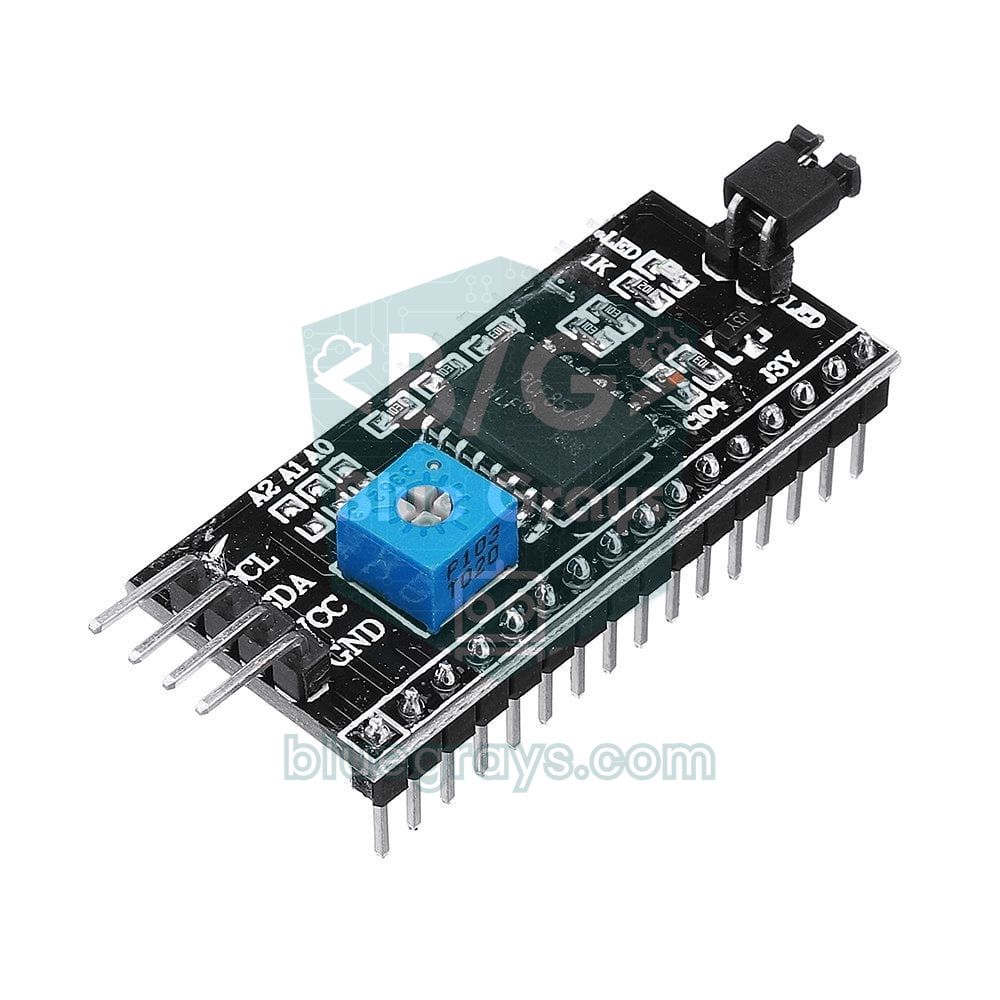
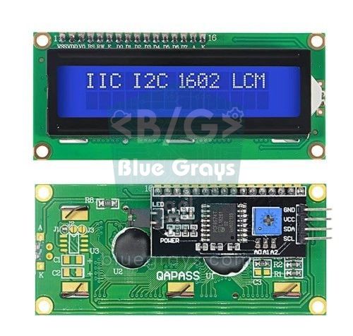
Take a close look at the blue or black I2C board soldered to the back of a 16x2 LCD and you will find a chip marked PCF8574T or PCF8574AT. The LiquidCrystal_I2C library drives the 8 pins of that chip as if they were wired straight to the LCD's parallel interface and sends data in 4-bit mode. That is also why the LCD address is usually 0x27 or 0x3F: on the backpack, A0–A2 are pulled up to VCC, so all three bits are 1, which gives 0x27 on a PCF8574T and 0x3F on a PCF8574AT. Bridge the A0–A2 solder pads on the back to change the address and run several LCDs on the same bus.
| PCF8574 pin | LCD connection |
|---|---|
| P0 | RS (command or data) |
| P1 | RW (read or write) |
| P2 | E (enable) |
| P3 | Backlight (through a transistor) |
| P4–P7 | D4–D7 (4-bit data bus) |
Using the PCF8574 with ESP32 and Raspberry Pi Pico
On the ESP32 both examples run unchanged; the only difference is that Wire.begin(21, 22) names the I2C pins explicitly, and the interrupt example already does that inside its #if defined(ESP32) block. On the Raspberry Pi Pico, MicroPython's machine.I2C class does the same job in a few lines: writeto() writes a byte and readfrom() reads one. The code below scans the I2C bus at startup, shows a running light on P0–P3 while no button is pressed and lights the matching LED when you press a button. Stay at 100 kHz; the PCF8574 datasheet does not guarantee higher speeds.
1# Raspberry Pi Pico + PCF8574 (MicroPython): P0-P3 LED, P4-P7 düğme / P0-P3 LEDs, P4-P7 buttons
2from machine import Pin, I2C
3import time
4
5i2c = I2C(0, sda=Pin(4), scl=Pin(5), freq=100000)   # PCF8574 en fazla 100 kHz / max 100 kHz
6ADDR = 0x20
7print("I2C:", [hex(a) for a in i2c.scan()])          # 0x20 görünmeli / 0x20 should appear
8
9
10def pcf_write(value):
11    i2c.writeto(ADDR, bytes([value]))
12
13
14def pcf_read():
15    return i2c.readfrom(ADDR, 1)[0]
16
17
18pcf_write(0xFF)                       # hepsi HIGH: LED'ler sönük / all HIGH: LEDs off
19led = 0
20while True:
21    buttons = pcf_read() >> 4         # basılı = 0 / pressed = 0
22    if buttons != 0x0F:
23        out = 0xF0 | buttons          # düğmeyi LED'e aynala / mirror buttons to LEDs
24    else:
25        out = 0xF0 | (~(1 << led) & 0x0F)   # yürüyen ışık / running light
26        led = (led + 1) % 4
27    pcf_write(out)
28    time.sleep_ms(150)
PCF8574 vs MCP23017 vs 74HC595
| Feature | PCF8574 | MCP23017 | 74HC595 |
|---|---|---|---|
| Extra pins | 8 | 16 | 8 outputs (chainable) |
| Interface | I2C, 2 wires | I2C, 2 wires (SPI version MCP23S17) | 3-wire serial (SPI-like) |
| Pin direction | Quasi-bidirectional | Each pin set as input or output | Output only |
| Output current | Sinks 25 mA when LOW, very weak when HIGH | 25 mA per pin, source and sink | A few mA per pin recommended |
| Internal pull-up | Weak current source (fixed) | 100 kΩ, enabled in software | None |
| Interrupt | 1 INT | 2 INT (INTA, INTB) | None |
| I2C speed | 100 kHz | Up to 1.7 MHz | - |
| Best for | Buttons, LEDs and simple I/O | Many pins, real output current and speed | Lots of LEDs and 7-segment displays |
If you only need to read a few buttons and light a few LEDs, the PCF8574 is the cheapest and simplest option. If you want to drive LEDs with HIGH, set the direction per pin, get 16 pins in one chip or run at 400 kHz and beyond, move up to the MCP23017. If you only need outputs for many LEDs or 7-segment displays, the 74HC595 shift register is faster and even cheaper.
PCF8574 project ideas
- Relay board: Drive an eight-channel relay module from a single I2C bus; active-LOW relay inputs match the PCF8574's logic perfectly.
- Keypad: Connect the 8 lines of a 4x4 keypad to the PCF8574 and save the Arduino's own pins for other parts.
- Button panel: Read 8 buttons for a game or a remote through the INT interrupt.
- Status display: Show the alarm state of several sensors on a bar of 8 LEDs.
- Multiple displays: Run two LCDs on the same Arduino using backpacks with different addresses.
- Knight Rider effect: Run a scanning light through the PCF8574 in a project that has no pins left.
Common problems and fixes
| Symptom | Likely cause | Fix |
|---|---|---|
| Does not show up in the I2C scan | SDA and SCL swapped or no common ground | Check the wiring; on the Uno SDA = A4, SCL = A5 |
| Address differs from what you expected | Chip is a PCF8574A or A0–A2 set differently | Check the 0x38–0x3F range and the jumpers |
| LED does not light or is very dim | Trying to drive the LED with HIGH | Anode to VCC through a resistor, cathode to the pin; write 0 |
| Button always reads 0 or always 1 | A 0 was written to the input pin earlier | Send a 1 to the inputs on every write (0xF0 | ...) |
| Interrupt fires once and never again | Port not read, so INT stays LOW | Read the port with read8() after every interrupt |
| Communication fails with many modules | Parallel pull-up resistors add up to too low a value | Remove the SDA/SCL resistors on some modules and shorten the wires |
The PCF8574 solves pin shortages with two wires and is easy to learn; once the quasi-bidirectional logic clicks, you can run LEDs, buttons, relays and LCDs on the same bus. In the BlueGrays app you will find I2C LCD, calculator, keypad, running light and button projects with step-by-step circuit diagrams and code, ready to be extended with a PCF8574 when you run out of pins.
Frequently asked questions
How do I find the I2C address of a PCF8574?
Depending on A0–A2, the PCF8574 sits between 0x20 and 0x27 and the PCF8574A between 0x38 and 0x3F. The surest way is to run an I2C scanner sketch and read the address in the Serial Monitor. On LCD backpacks it is usually 0x27 or 0x3F.
How many PCF8574 modules can I connect to one Arduino?
Each PCF8574 adds 8 pins and A0–A2 allow 8 addresses, so modules of one type give you 64 pins. Because the PCF8574 and PCF8574A use different address ranges, mixing them gets you to 16 modules and 128 pins. With many modules, watch the combined value of the I2C pull-up resistors.
Why does the LED on a PCF8574 light up when the pin is LOW?
PCF8574 pins can sink up to 25 mA when LOW but only source about 100 µA when HIGH. That is why the LED's anode goes to VCC through a resistor and its cathode to the pin, so writing 0 turns it on. Wired the other way round, the LED stays dark or very dim.
How do I read a button with the PCF8574?
First write a 1 to the pin so it rests HIGH through the weak pull-up. When the button pulls the pin to GND, you read a 0. If you write a 0 to an input instead, it is held LOW permanently and the button can no longer be read.
PCF8574 or MCP23017: what is the difference?
The PCF8574 is a simple chip with 8 quasi-bidirectional pins and a 100 kHz limit. The MCP23017 offers 16 pins, per-pin direction, switchable pull-ups, two interrupt outputs and I2C speeds up to 1.7 MHz. For simple button and LED jobs the PCF8574 is enough; for bigger projects the MCP23017 is the better pick.
Does the PCF8574 work with an ESP32 at 3.3 V?
Yes, the PCF8574 runs from 2.5 to 6 V, so it works directly with the ESP32 and Raspberry Pi Pico. Power it from 3.3 V; at 5 V the pull-ups drag SDA and SCL to 5 V, which can harm 3.3 V boards. On the ESP32, set the I2C pins with Wire.begin(21, 22).
Projects to build after reading this
See all projects
LED Chaser
Lights that switch on one after another, as if they were running. The Arduino lights six LEDs one at a time; each glows for a brief moment and goes out, so the light walks from start to end and then…

Knight Rider LED Effect
The classic scanner light: a dot of light slides from one end of six LEDs to the other and then comes back.

LED Control with a Push Button (Push)
Just like a doorbell: the light stays on as long as you press, and goes off when you let go.

Toggle an LED with a Button (On/Off)
Press the button once and the light comes on, press it again and it goes off, just like the light switch in your room.
Using LCD Screen with I2C
Give your Arduino its own screen and make it write its first message. The two-line LCD screen hooks up with just a few wires; a greeting appears on the top line, then a second message on the bottom…

ESP32 I2C LCD Display (16x2)
In this project we connect a 16x2 character LCD to the ESP32 over I2C and display text. With I2C, just 2 data pins (SDA and SCL) control the screen, instead of the 6+ pins a classic parallel connection wastes. The code prints a fixed message on the first line and a counter that goes up every second on the second. At startup an I2C scanner also prints the display's address to the Serial Monitor (usually 0x27 or 0x3F).

Arduino I2C Calculator
It is an Arduino-based calculator project that performs addition, subtraction, multiplication and division operations using a 4x4 membrane keypad and a 16x2 I2C LCD display. Thanks to I2C, the display connection is provided with only 2 cables, thus reducing cable clutter and keeping more pins open for use. There is also decimal number input and negative number support.
4x4 Keypad Operation
On the 4x4 keypad, which looks a lot like a phone's buttons, the Arduino instantly knows which key you pressed and writes it to your computer screen.