
What Is a Pull-up Resistor? Pull-down, INPUT_PULLUP & Values
What are pull-up and pull-down resistors, and why does a floating input misbehave? INPUT_PULLUP, ESP32 and Pico internal resistors, I2C pull-ups and picking 10k.
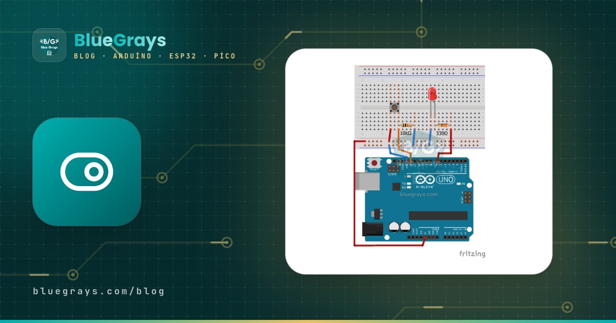
A pull-up resistor is a resistor, usually around 10 kΩ, that connects a microcontroller input to the supply voltage (VCC) when nothing else is driving it, keeping the pin at a stable HIGH level. A pull-down resistor does the same job in reverse: it pulls the pin to ground (GND) and holds it LOW. These small resistors are the secret behind a button, switch or reed switch giving a steady reading on your Arduino instead of jumping around randomly. On most boards the resistor is already built into the chip; on Arduino, writing INPUT_PULLUP is enough to turn it on.
In this post you'll learn step by step why a floating input produces random values, the difference between pull-up and pull-down, the internal resistors on the Arduino Uno, ESP32 and Raspberry Pi Pico, how to calculate the right resistor value, and why the I2C bus doesn't work without pull-ups. Every section has real measurements, formulas and code you can upload directly.
What is a floating input, and why is it a problem?
A digital input pin is a very high-impedance gate (hundreds of megaohms) that only senses voltage and draws almost no current. If nothing is connected to the pin, or the pin is connected to nothing while the button is open, its voltage is undefined. This is called a floating input. Such a pin acts like a tiny antenna: it picks up nearby wires, the 50 Hz field from mains power, even your finger as it approaches, and the reading flips between 0 and 1 dozens of times per second.
To understand the problem you need to look at logic thresholds. When the Arduino Uno's ATmega328P runs at 5 V, it treats anything above 3 V (60% of VCC) as a definite HIGH and anything below 1.5 V (30% of VCC) as a definite LOW. The region in between is undefined, and a floating pin often wanders right through it. The result: an LED lighting up without you pressing the button, a counter increasing randomly, or an interrupt firing constantly. To see it yourself, connect just a loose jumper wire to D2 with no button yet, upload the code below and touch the end of the wire while the Serial Monitor is open:
1void setup() {
2  Serial.begin(9600);
3  pinMode(2, INPUT);                // pull direnci yok, pin havada / no pull resistor, pin is floating
4}
5
6void loop() {
7  Serial.println(digitalRead(2));   // rastgele 0 ve 1 görürsün / you will see random 0s and 1s
8  delay(100);
9}
What are pull-up and pull-down resistors, and how do they work?
In a pull-up setup, one end of the resistor connects to the input pin and the other to VCC, while the button goes between the pin and GND. With the button open, almost no current flows through the pin, so there's no voltage drop across the resistor and the pin sees VCC, which is HIGH. When you press the button, the pin is connected straight to GND and reads LOW. A small current flows through the resistor at that moment: by Ohm's law, I = V / R, which is 0.5 mA at 5 V and 10 kΩ. If you had connected the pin directly to VCC instead of through a resistor, pressing the button would short the supply; the resistor both pulls the pin up and prevents that short circuit. You can quickly find the current for other values with the Ohm's law calculator.
A pull-down setup is the mirror image: the resistor goes between the pin and GND, and the button between the pin and VCC. With the button open, the pin is pulled to ground through the resistor and reads LOW; when pressed, the pin connects to VCC and reads HIGH. This feels more natural to beginners, because pressed means 1 and released means 0. However, the Arduino Uno's chip has no internal pull-down; if you want a pull-down on an Uno, you need an external 10 kΩ resistor. The ESP32 and Raspberry Pi Pico include both resistors inside.
| Feature | Pull-up | Pull-down |
|---|---|---|
| Where does the resistor go? | Between the pin and VCC | Between the pin and GND |
| Where does the button go? | Between the pin and GND | Between the pin and VCC |
| Button released | HIGH (1) | LOW (0) |
| Button pressed | LOW (0) | HIGH (1) |
| Logic type | Active low | Active high |
| Internal support | Uno, ESP32, Pico | ESP32, Pico |
| Typical use | Buttons, I2C, reset line | MOSFET gates, sensor outputs |
Internal pull-up and pull-down resistors: Arduino Uno, ESP32 and Pico
| Feature | Arduino Uno | ESP32 | Raspberry Pi Pico |
|---|---|---|---|
| Logic level | 5 V | 3.3 V | 3.3 V |
| Internal pull-up | Yes, 20–50 kΩ | Yes, about 45 kΩ | Yes, 50–80 kΩ |
| Internal pull-down | None | Yes, about 45 kΩ | Yes, 50–80 kΩ (problematic on Pico 2) |
| Enabling in code | INPUT_PULLUP | INPUT_PULLUP / INPUT_PULLDOWN | Pin.PULL_UP / Pin.PULL_DOWN |
| Pull-up button (pin – GND) | D2 | GPIO 18 | GP2 |
| Pull-down button (pin – VCC) | D3 + external 10 kΩ | GPIO 19 (to 3V3) | GP3 (to 3V3) |
| Pins without internal resistors | None | GPIO 34–39 | None |
| I2C pins (SDA / SCL) | A4 / A5 | GPIO 21 / GPIO 22 | GP4 / GP5 |
Using INPUT_PULLUP on Arduino, step by step
- Connect one leg of the first button to D2 and the diagonally opposite leg to GND; this button needs no resistor, because the internal pull-up will be used.
- Connect one leg of the second button to D3 and the diagonally opposite leg to 5V.
- Place an external 10 kΩ pull-down resistor between D3 and GND (colour bands brown-black-orange).
- Upload the code, open the Serial Monitor at 9600 baud and press the two buttons in turn.
- Check that released buttons show 0 and pressed buttons show 1; the built-in LED on D13 lights when either button is pressed.
1const int BTN_PULLUP = 2;     // buton D2 - GND, dahili pull-up / button D2 - GND, internal pull-up
2const int BTN_PULLDOWN = 3;   // buton D3 - 5V, harici 10k D3 - GND / button D3 - 5V, external 10k D3 - GND
3const int LED_PIN = 13;       // dahili LED / built-in LED
4
5void setup() {
6  Serial.begin(9600);
7  pinMode(BTN_PULLUP, INPUT_PULLUP);   // dahili pull-up açık / internal pull-up enabled
8  pinMode(BTN_PULLDOWN, INPUT);        // Uno'da dahili pull-down yok / Uno has no internal pull-down
9  pinMode(LED_PIN, OUTPUT);
10}
11
12void loop() {
13  bool a = (digitalRead(BTN_PULLUP) == LOW);     // pull-up: basınca LOW / pull-up: LOW when pressed
14  bool b = (digitalRead(BTN_PULLDOWN) == HIGH);  // pull-down: basınca HIGH / pull-down: HIGH when pressed
15  digitalWrite(LED_PIN, (a || b) ? HIGH : LOW);
16  Serial.print(a ? 1 : 0);
17  Serial.print(' ');
18  Serial.println(b ? 1 : 0);
19  delay(50);
20}
The line pinMode(BTN_PULLUP, INPUT_PULLUP) turns on the 20–50 kΩ resistor inside the chip, so D2 reads HIGH when the button isn't pressed and LOW when it is. D3, on the other hand, is set as a plain INPUT, because the external 10 kΩ resistor is pulling it down. In the code we used comparisons to give the two different logics the same meaning: the pull-up button counts as pressed when it's LOW, and the pull-down button when it's HIGH. The old Arduino pattern of pinMode(pin, INPUT) followed by digitalWrite(pin, HIGH) turns on the same internal pull-up; INPUT_PULLUP is simply the more readable version.
INPUT_PULLUP and INPUT_PULLDOWN on the ESP32
Almost every GPIO pin on the ESP32 has both a pull-up and a pull-down resistor of about 45 kΩ. In the Arduino core you enable them with the INPUT_PULLUP and INPUT_PULLDOWN constants, which are the same in both ESP32 Arduino core 2.x and 3.x. Because the ESP32 runs at 3.3 V, you must connect the other end of the pull-down button to the 3V3 pin, not 5V; GPIO pins are not 5 V tolerant. In the example below, the button on GPIO 18 goes to GND and the button on GPIO 19 goes to 3V3, and no external resistors are needed.
1const int BTN_PULLUP = 18;     // buton GPIO18 - GND / button GPIO18 - GND
2const int BTN_PULLDOWN = 19;   // buton GPIO19 - 3V3 / button GPIO19 - 3V3
3const int LED_PIN = 2;         // çoğu kartta dahili LED / built-in LED on most boards
4
5void setup() {
6  Serial.begin(115200);
7  pinMode(BTN_PULLUP, INPUT_PULLUP);       // dahili pull-up / internal pull-up
8  pinMode(BTN_PULLDOWN, INPUT_PULLDOWN);   // dahili pull-down / internal pull-down
9  pinMode(LED_PIN, OUTPUT);
10}
11
12void loop() {
13  bool a = (digitalRead(BTN_PULLUP) == LOW);     // pull-up: basınca LOW / pull-up: LOW when pressed
14  bool b = (digitalRead(BTN_PULLDOWN) == HIGH);  // pull-down: basınca HIGH / pull-down: HIGH when pressed
15  digitalWrite(LED_PIN, (a || b) ? HIGH : LOW);
16  Serial.print(a ? 1 : 0);
17  Serial.print(' ');
18  Serial.println(b ? 1 : 0);
19  delay(50);
20}
Pin.PULL_UP and Pin.PULL_DOWN on the Raspberry Pi Pico
The Raspberry Pi Pico's RP2040 chip has internal pull-up and pull-down resistors of roughly 50–80 kΩ on every GPIO. In MicroPython, you just pass Pin.PULL_UP or Pin.PULL_DOWN as the third parameter when creating the pin object. In the code below, the button on GP2 goes to GND and the button on GP3 goes to 3V3; when either is pressed, the onboard LED lights.
1from machine import Pin
2import time
3
4btn_up = Pin(2, Pin.IN, Pin.PULL_UP)       # buton GP2 - GND / button GP2 - GND
5btn_down = Pin(3, Pin.IN, Pin.PULL_DOWN)   # buton GP3 - 3V3 / button GP3 - 3V3
6led = Pin(25, Pin.OUT)                     # dahili LED, Pico W'de LED adini kullan / onboard LED, use the LED name on Pico W
7
8while True:
9    a = btn_up.value() == 0       # pull-up: basinca 0 / pull-up: 0 when pressed
10    b = btn_down.value() == 1     # pull-down: basinca 1 / pull-down: 1 when pressed
11    led.value(1 if (a or b) else 0)
12 time.sleep_ms(20)How do you choose a pull-up resistor value?
The smaller the pull resistor, the harder it pulls the pin, but the more current it wastes when the button is pressed. The larger it is, the less current it draws, but the weaker the pin becomes against noise and the slower voltage changes get. The formula for current is simple: I = VCC / R. At 5 V, 1 kΩ means 5 mA per pressed button; 10 kΩ means 0.5 mA; and 100 kΩ means only 0.05 mA, or 50 µA. In battery-powered devices where a button may stay pressed for a long time, this difference directly affects battery life.
Two factors set the upper limit. The first is leakage current: an ATmega328P input leaks at most about 1 µA; across a 100 kΩ pull-up that causes only a 0.1 V drop and is no problem, but at 1 MΩ the drop rises to 1 V and the pin approaches the threshold. The second is speed: the resistor forms an RC circuit with the capacitance of the pin and wire, with time constant τ = R × C. With 10 kΩ and a 100 pF wire, τ = 1 µs, which is more than fast enough for a button. The general rule is: 10 kΩ for buttons, 1–4.7 kΩ for long, noisy wires, and 47–100 kΩ where you need to save battery. You can use the resistor colour code tool to decode a resistor's colour bands.
| Application | Recommended value | Reason |
|---|---|---|
| Button, switch, reed switch | 10 kΩ (or internal) | 0.5 mA at 5 V, a strong enough pull |
| Button with wire longer than 1 m | 1–4.7 kΩ | Harder pull against noise |
| Battery-powered device | 47–100 kΩ | Only about 50–100 µA while pressed |
| MOSFET gate (pull-down) | 10–100 kΩ | Stops the motor running by itself at power-up |
| I2C, 100 kHz | 4.7 kΩ | Rise time stays under the 1000 ns limit |
| I2C, 400 kHz | 2.2 kΩ | Smaller value to meet the 300 ns limit |
Pull-up resistors on the I2C bus
On the I2C bus, pull-up resistors are not an option but a requirement. The devices on the SDA and SCL lines use open-drain outputs: they can only pull the line to GND, never drive it HIGH. The only thing that brings the line back to HIGH is the pull-up resistors. This way, even if two devices try to talk at the same time, no short circuit occurs; when one pulls the line LOW, the other simply sees it. Without pull-ups, the I2C scanner finds no devices or your program hangs in the Wire functions. For protocol details, see What Is I2C.
On the Arduino Uno, the Wire library turns on the internal pull-ups when it starts, but 20–50 kΩ is too weak for I2C and only works by luck on short wires. Fortunately, most ready-made modules such as an OLED, BME280 or I2C LCD already have 4.7 kΩ or 10 kΩ pull-ups soldered on the board. An often overlooked point is parallel connection: if you connect three modules, each with a 10 kΩ pull-up, to the same bus, the equivalent resistance drops to 3.3 kΩ, and with six modules to 1.7 kΩ, making it harder for devices to pull the line LOW. For the calculation, the minimum resistance is Rmin = (VCC − 0.4 V) / 3 mA, about 1 kΩ at 3.3 V; the maximum resistance is found with Rmax = tr / (0.8473 × Cb). At 400 kHz (tr = 300 ns) and 100 pF of bus capacitance, Rmax comes out at about 3.5 kΩ. You can easily find parallel values with the series-parallel resistor calculator.
| Mode | Speed | Maximum rise time | Typical pull-up (3.3 V) |
|---|---|---|---|
| Standard mode | 100 kHz | 1000 ns | 4.7–10 kΩ |
| Fast-mode | 400 kHz | 300 ns | 2.2–4.7 kΩ |
| Fast-mode Plus | 1 MHz | 120 ns | 1–1.5 kΩ |
Where will you need pull resistors? Project ideas
- Reading buttons and switches: Every button needs a pull resistor; this is covered together with debounce in the button wiring guide.
- Door and window sensor: A reed switch closes when a magnet gets close; with INPUT_PULLUP it can be read with a single wire.
- Code lock: The keypad library uses internal pull-ups on the row pins, so a 4x4 keypad needs no extra resistors.
- Driving motors and LED strips: A 10 kΩ pull-down on the gate of a MOSFET stops the motor from spinning while the Arduino is starting and the pin isn't configured yet.
- Instant response with interrupts: If interrupt pins are left floating, they trigger constantly; a pull-up makes them stable.
- Rotary encoder: Rotary encoder outputs are read with pull-ups; with bare encoders that have no module, you need to enable the internal pull-up.
- Sensor and display bus: When you put I2C modules such as an OLED, BME280 and RTC on the same bus, calculate the total pull-up value.
Common mistakes and how to fix them
| Symptom | Likely cause | Fix |
|---|---|---|
| LED flickers without pressing the button | Pin is floating, no pull resistor | Use INPUT_PULLUP or add an external 10 kΩ resistor |
| Reading changes when you bring your hand close | Floating input, long wire acting like an antenna | Use a smaller pull resistor (4.7 kΩ), shorten the wire |
| Button always looks pressed | Pull-up logic read the wrong way round | Treat LOW as pressed or use !digitalRead |
| Pin sits between 1–2 V when pressed | Internal pull-up and external pull-down are active together | Use only one; set pinMode to INPUT |
| INPUT_PULLUP doesn't work on ESP32 GPIO 35 | GPIO 34–39 have no internal resistors | Add an external 10 kΩ pull-up |
| ESP32 won't start or keeps resetting | Pull-up on GPIO 12 or pull-down on GPIO 0 | Move the button to a GPIO that isn't a strapping pin |
| I2C device not found or Wire hangs | No pull-ups, or too many modules' resistors in parallel | Add 4.7 kΩ or remove resistors from the extra modules |
| ESP32 or Pico I2C pins get damaged | Pull-ups connected to 5 V | Connect pull-ups to 3.3 V, use a logic level shifter if needed |
| Multiple counts per press | Button bounce (debounce), unrelated to the pull | Apply 20–50 ms debounce in software |
Pull-up and pull-down resistors are small, but they're among the most widely used building blocks in electronics; once you grasp the logic, buttons, sensors and I2C lines stop springing surprises. To reinforce what you've learned, check out the button-and-LED, ESP32 button control and Pico debounce comparison projects in the BlueGrays app; each comes with a step-by-step circuit diagram and ready-made code.
Frequently asked questions
How many ohms should a pull-up resistor be?
The most common value for buttons and switches is 10 kΩ; it draws only 0.5 mA when pressed at 5 V and is strong enough against noise. On long wires you can go down to 4.7 kΩ, and in battery-powered circuits up to 47–100 kΩ. On an I2C bus, 4.7 kΩ is preferred for 100 kHz and 2.2 kΩ for 400 kHz.
What is the difference between INPUT and INPUT_PULLUP?
A pin in INPUT mode only reads voltage and isn't pulled in either direction; without an external resistor, the pin floats. INPUT_PULLUP turns on the 20–50 kΩ resistor inside the chip and connects the pin to VCC. That way you just wire the button between the pin and GND and read LOW when it's pressed.
Does the Arduino Uno have an internal pull-down resistor?
No. The AVR chips in the Uno, Nano and Mega only have internal pull-ups, and the INPUT_PULLDOWN constant isn't defined on these boards. If you need a pull-down, connect an external 10 kΩ resistor between the pin and GND. The ESP32 and Raspberry Pi Pico do support internal pull-downs.
Do I need pull-up resistors for I2C?
Yes. Because I2C devices can only pull the lines LOW, pull-up resistors that bring SDA and SCL HIGH are essential. Most ready-made modules have 4.7 kΩ or 10 kΩ resistors on the board, so with a single module you don't need any extra. If you're using a bare sensor chip or the bus is long, add 4.7 kΩ on both lines.
Should I use a pull-up or a pull-down?
In most cases a pull-up is more practical: it's built into every board, and wiring the button to GND is safer than running the supply line around with a wire. A pull-down is preferred where you want to read 1 when pressed, or on lines like a MOSFET gate that must stay LOW at power-up. Whichever you choose, just set up the logic in your code to match.
What happens if I connect a button without a pull-up resistor?
With the button open, the pin isn't connected to anything, so it floats and picks up electrical noise from its surroundings. digitalRead then returns random 0s and 1s, the LED flickers by itself, or an interrupt fires constantly. To fix it, just use INPUT_PULLUP or add an external resistor.
Projects to build after reading this
See all projects
LED Control with a Push Button (Push)
Just like a doorbell: the light stays on as long as you press, and goes off when you let go.

Toggle an LED with a Button (On/Off)
Press the button once and the light comes on, press it again and it goes off, just like the light switch in your room.

ESP32 LED Control with Push Button (Push)
The LED lights up when the button is pressed and turns off when released. Shows how the ESP32's digital input pin and internal pull-up resistor are used. The INPUT_PULLUP mode eliminates the need for an external resistor.

ESP32 LED Control with Pushbutton (Toggle)
Each time the button is pressed the state of the LED changes: if it is on it turns off, if it is off it turns on. Classic toggle pattern. With debounce we clean up the mechanical noise of the pushbutton to ensure a single toggle with a single press.
Raspberry Pi Pico Button Controlled LED (Push)
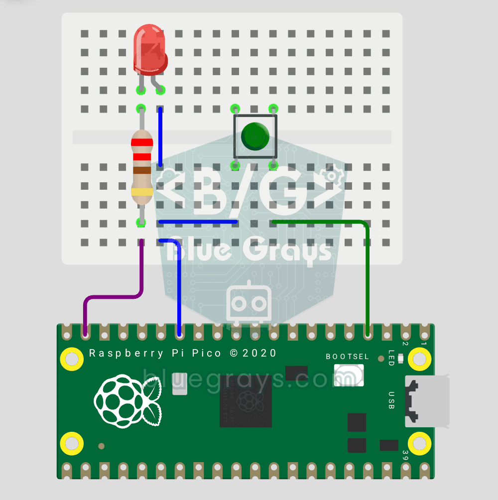
First input project with Pico — button read! LED lights while button is pressed, off when released. This is the big step after LED animations: signal input from the world to Pico. Learn Pin.IN (input mode), Pin.PULL_UP (internal pull-up resistor — standard for buttons), button.value() reading. GP14 LED, GP2 button (internal PULL_UP). Pressed = LOW (0), released = HIGH (1) — reverse logic seems confusing at first but is industry standard.
Raspberry Pi Pico Button Toggle LED
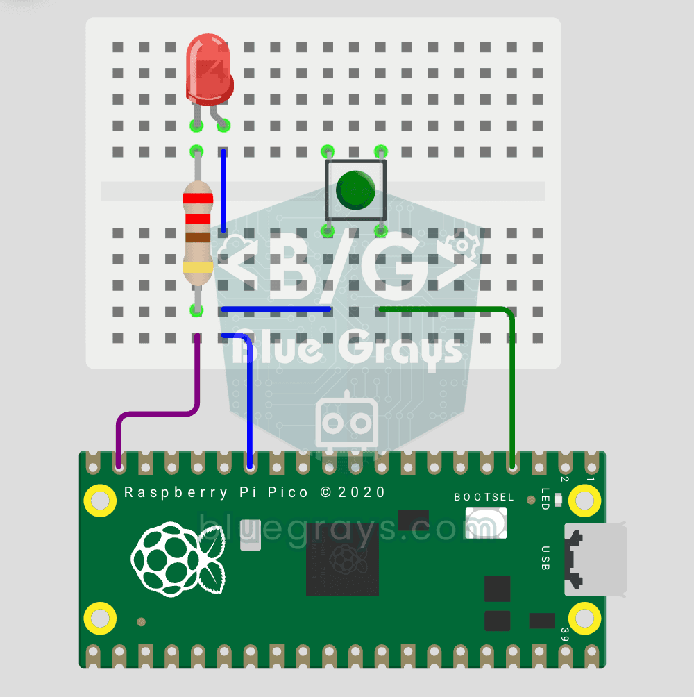
Button + LED — next level! Unlike the basic button project, there is no need to hold the button. Press and release → LED on. Press and release again → LED off (toggle). Same circuit (LED GP14, Button GP2), but big code difference. Learn edge detection (capturing the 1→0 falling moment), state tracking, debounce (mechanical bounce filter). MicroPython's led.toggle() swaps state in one line. Foundation of all interactive button projects (mode switcher, IRQ, double-click).
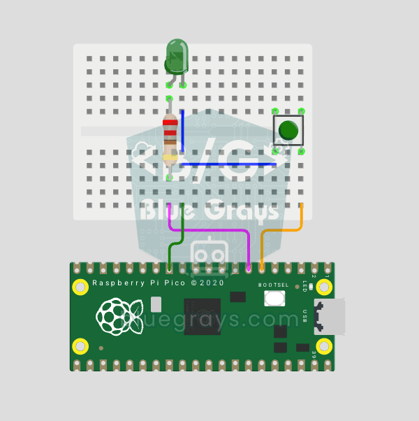
Raspberry Pi Pico Button Debounce: IRQ vs Software Polling
If one press of a button made your code count 3-4 times, the culprit is contact bounce: the button's metal contacts open and close many times within microseconds as they touch! In this project we count the same button in 2 different ways and compare them side by side in Serial: RAW polling (catches the bounce and miscounts) and IRQ + software debounce (counts correctly).
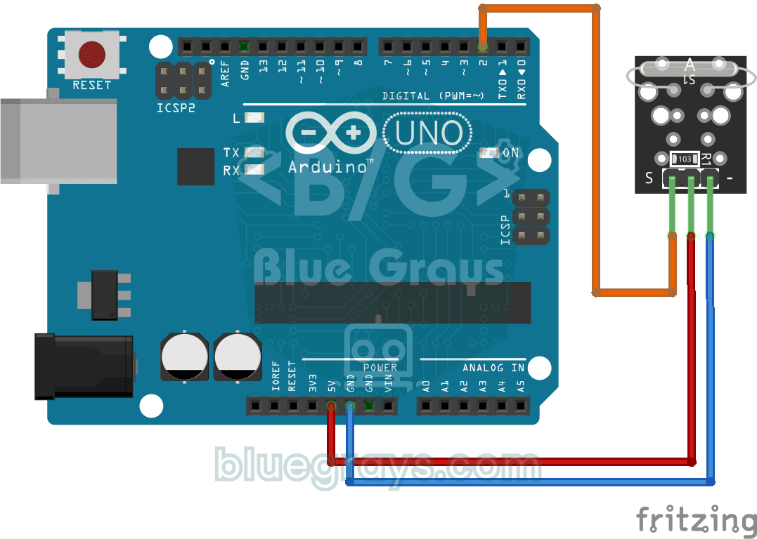
Reading a Reed Switch
Ever wondered about the magnetic switch inside door and window alarms? When a magnet comes near the reed relay module, the tiny switch inside it closes; the Arduino reads it once a second and prints…