
Voltage Divider: Formula, Resistor Choice and Arduino Examples
How does a voltage divider work? Vout = Vin × R2 / (R1 + R2), choosing resistors, loading effect, measuring 12 V with Arduino, 5 V to 3.3 V, LDR and NTC.
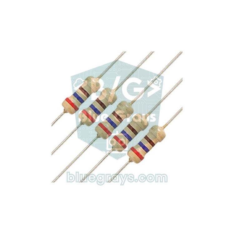
A voltage divider is the simplest circuit for turning a voltage into a smaller, predictable one using two resistors in series. The output voltage is given by Vout = Vin × R2 / (R1 + R2): R1 connects to the source, R2 connects to ground (GND), and the output is taken from the midpoint where they meet. For example, two 10 kΩ resistors split 12 V exactly in half, to 6 V. These two resistors sit at the heart of countless circuits, from measuring a 12 V battery with an Arduino and bringing a 5 V sensor signal down to the 3.3 V pins of an ESP32, to reading sensors such as LDRs and NTC thermistors.
In this guide you'll see, with real numbers, where the formula comes from, how to choose the resistor values and why the output drops when you connect something to the divider (the loading effect). Then we'll build, step by step, code that measures battery voltage with an Arduino Uno, ESP32 and Raspberry Pi Pico, pick the right resistor pairs for turning 5 V into 3.3 V, and read an LDR and an NTC with a divider. Finally, we'll explain why a voltage divider should never be used in place of a power supply.
What is a voltage divider and how does it work?
The voltage divider formula comes straight from Ohm's law. The same current flows through R1 and R2, which are connected in series between the source and ground: I = Vin / (R1 + R2). The voltage across R2, which is the output, is that current multiplied by R2: Vout = I × R2 = Vin × R2 / (R1 + R2). In short, the source voltage is shared between the resistors in proportion to their values; the larger resistor gets the larger share. The output is always smaller than the input, because the ratio R2 / (R1 + R2) is less than 1. You'll find more detail on how voltage is shared in series circuits in Series and Parallel Resistor Calculation.
| Quantity | Formula | Example (Vin = 12 V, R1 = 22 kΩ, R2 = 10 kΩ) |
|---|---|---|
| Output voltage | Vout = Vin × R2 / (R1 + R2) | 12 × 10 / 32 = 3.75 V |
| Division ratio | k = R2 / (R1 + R2) | 10 / 32 = 0.3125 |
| Input from the output | Vin = Vout × (R1 + R2) / R2 | 3.75 × 3.2 = 12 V |
| R1 for a desired ratio | R1 = R2 × (Vin / Vout − 1) | 10 kΩ × (12 / 3.75 − 1) = 22 kΩ |
| Divider current | I = Vin / (R1 + R2) | 12 / 32 kΩ = 0.375 mA |
| Total power | P = Vin² / (R1 + R2) | 144 / 32 kΩ = 4.5 mW |
| Output resistance (Thevenin) | Rth = R1 × R2 / (R1 + R2) | 22 × 10 / 32 = 6.875 kΩ |
You can also work backwards: if you want to bring 12 V down to 3.3 V and you've picked 10 kΩ for R2, you get R1 = 10 × (12 / 3.3 − 1) ≈ 26.4 kΩ. That value isn't sold, so you choose the next standard value up, 27 kΩ, and the output becomes 12 × 10 / 37 ≈ 3.24 V. Rounding R1 up lowers the output slightly, which is the safe side for the pin. A potentiometer is really an adjustable voltage divider too: its wiper splits the resistive track into R1 and R2. If you'd rather not do the maths by hand, the voltage divider calculator gives you the output instantly from the input voltage and the resistors. In electronics you'll mostly see voltage dividers doing these jobs:
- Measuring higher voltages: bringing sources such as a 12 V battery or a 7.4 V lithium pack down into the range an analog input can measure.
- Level shifting down: making a 5 V signal safe for the 3.3 V inputs of an ESP32 or Raspberry Pi Pico.
- Reading resistive sensors: turning the resistance change of parts such as LDRs, NTCs, flex sensors and force sensors (FSR) into a voltage.
- Reading many buttons on one pin: a resistor ladder gives each button a different voltage, so five buttons can share a single analog pin.
- Regulator feedback: regulators such as the LM317 and the adjustable LM2596 keep their output steady by measuring it through a divider; for the LM317, Vout = 1.25 × (1 + R2 / R1).
- Creating a reference voltage: producing half the supply voltage as a reference in op-amp circuits.
How to choose the resistor values
The formula only cares about the ratio: 1 kΩ + 1 kΩ and 100 kΩ + 100 kΩ divide by the same amount, exactly in half. In practice, though, the absolute values matter too. Small resistors let a lot of current flow through the divider; that current is wasted energy and drains the battery for nothing in battery-powered projects. Large resistors draw very little current, but their output is weak: a connected load or the sampling capacitor inside the analog input easily disturbs the output voltage, and noise picked up by the wires gets in more easily. The right choice is a balance between these two extremes:
| Total resistance (R1 + R2) | Current at 12 V | Pros | Cons | Typical use |
|---|---|---|---|---|
| 100 Ω – 1 kΩ | 12–120 mA | Barely affected by the load, very fast | Gets warm, wastes a lot of current | Almost never in measurement circuits |
| 1 kΩ – 30 kΩ | 0.4–12 mA | Ideal output resistance for an ADC, suits fast signals | Constant current drain in battery projects | 5 V → 3.3 V signal conversion, measuring with Arduino |
| 30 kΩ – 300 kΩ | 40–400 µA | Battery friendly, no heating | May need a 100 nF capacitor at the analog input | Battery monitoring |
| 1 MΩ and above | Less than 12 µA | Draws almost no current | Prone to noise, the ADC can't read it accurately, even a multimeter loads it | Only with an op-amp buffer |
- Find the highest input voltage. A 12 V lead-acid battery can reach 14.4 V while charging; take the worst case of the voltage you'll measure and add a 10% margin.
- Find the highest voltage the pin accepts. 5 V on the Arduino Uno, 3.3 V on the ESP32 and Pico; as safe targets, choose about 4.5 V on the Uno, 2.5 V on the ESP32 and 3.0 V on the Pico.
- Calculate the ratio: k = target output / highest input. For example, 4.5 / 14.4 ≈ 0.31.
- Pick R2 (10 kΩ is a good starting point in most cases) and find R1 with R1 = R2 × (1 / k − 1). Round the result up to the next value among the standard resistor values.
- Check the current and power: I = Vin / (R1 + R2) and P = Vin² / (R1 + R2). In battery projects, try to keep the current in the microamp range.
- Check the output resistance: R1 × R2 / (R1 + R2) should be below 10 kΩ for the Arduino Uno; if it isn't, add a 100 nF capacitor between the analog pin and GND.
- Put the real ratio in your code: recalculate the ratio with the standard values you chose, then measure with a multimeter once the circuit is built and calibrate.
Loading effect: what happens when you connect something to the divider?
The formula assumes no current is drawn from the output. As soon as you connect a load, it ends up in parallel with R2, the equivalent resistance of the lower leg shrinks and the output voltage drops. The easy way to calculate this is to treat the divider as its Thevenin equivalent: a source with the voltage you measure with no load (Vth) and an internal resistance Rth = R1 × R2 / (R1 + R2). With a load RL, the output becomes Vth × RL / (Rth + RL). The table below shows a 10 V source divided by 10 kΩ + 10 kΩ (Vth = 5 V, Rth = 5 kΩ) with different loads on the output:
| Load on the output (RL) | Output voltage | Error |
|---|---|---|
| No load | 5.00 V | 0% |
| 1 MΩ | 4.98 V | 0.5% |
| 100 kΩ | 4.76 V | 4.8% |
| 10 kΩ | 3.33 V | 33% |
| 1 kΩ | 0.83 V | 83% |
The rule of thumb: if the load resistance is at least 100 times the divider's output resistance (Rth), the error stays below 1%. If the load is smaller, either make the resistors smaller or put an op-amp voltage follower (buffer) in between. A microcontroller's analog input has a very high resistance itself, but inside it there's a small sampling capacitor that gets charged at every conversion (about 14 pF on the ATmega328P). That's why the datasheet recommends a source output resistance of about 10 kΩ or less. If you use a higher-value divider, add a 100 nF capacitor between the analog pin and GND: it keeps the charge needed at the moment of sampling ready. And if you read several analog pins in turn, discarding the first reading on each pin clears the error left over from switching channels.
Why a voltage divider can't be used as a power supply
The most common beginner trap is taking 5 V from a 12 V adapter with two resistors and trying to power an Arduino or a module from it. On paper, a 7 kΩ and 5 kΩ divider gives exactly 5 V from 12 V, but only while no current is drawn from the output. A board drawing 50 mA behaves like a load of about 100 Ω; in parallel with the 5 kΩ R2, the lower leg drops to 98 Ω and the output collapses to 0.17 V. If you shrink the resistors to 70 Ω and 50 Ω, the circuit now draws 100 mA and turns 1.2 W into heat even with nothing connected; with the load attached the output still sags to 3.9 V, and every time the board's current changes (Wi-Fi, a servo, a relay) the voltage moves too. What's more, when the load is removed the voltage climbs back up and can damage sensitive parts.
Measuring 12 V battery and cell voltage with Arduino
The Arduino Uno's analog inputs can read at most 5 V; connecting a 12 V battery directly would destroy the pin. The answer is a divider of 22 kΩ (R1) and 10 kΩ (R2): with a ratio of 0.3125, a charging voltage of 14.4 V reaches the pin as 4.5 V, and the circuit can measure up to 16 V. At 12 V the divider draws only 0.375 mA, and its 6.9 kΩ output resistance is below the recommended 10 kΩ limit. The 10-bit ADC resolves about 4.9 mV per step; with the divider that's a resolution of about 15.6 mV at the input. Because the ESP32 and Pico run at 3.3 V, we use a larger R1 (56 kΩ) on those boards:
| Connection | Arduino Uno | ESP32 | Raspberry Pi Pico |
|---|---|---|---|
| R1 (top resistor) | 22 kΩ | 56 kΩ | 56 kΩ |
| R2 (bottom resistor) | 10 kΩ | 10 kΩ | 10 kΩ |
| Top end of R1 | Source positive (+12 V) | Source positive (+12 V) | Source positive (+12 V) |
| Midpoint (R1–R2) | A0 | GPIO 34 (ADC1) | GP26 (ADC0, pin 31) |
| Bottom end of R2 and source negative | GND | GND | GND (e.g. pin 38) |
| Pin voltage at 14.4 V | 4.50 V | 2.18 V | 2.18 V |
| Highest measurable input | 16 V | About 16 V (accurate range) | About 21 V |
1// 12 V akü gerilimini gerilim bölücüyle ölçme / Measuring a 12 V battery with a voltage divider
2// Kaynak + -> 22k (R1) -> A0 -> 10k (R2) -> GND / Source + -> 22k (R1) -> A0 -> 10k (R2) -> GND
3// Kaynağın eksisi Arduino GND'sine bağlı / Source minus is tied to the Arduino GND
4const int VIN_PIN = A0;
5const float VREF = 5.0;      // 5V pininde ölçtüğün gerilim / voltage you measured on the 5V pin
6const float R1 = 22000.0;    // üst direnç (ohm) / top resistor (ohms)
7const float R2 = 10000.0;    // alt direnç (ohm) / bottom resistor (ohms)
8const float CAL = 1.000;     // kalibrasyon: gerçek / okunan / calibration: real / measured
9const float LOW_V = 11.8;    // düşük akü eşiği (V) / low battery threshold (V)
10
11float readInputVoltage() {
12  analogRead(VIN_PIN);                        // ilk okumayı at / discard the first reading
13  long sum = 0;
14  for (int i = 0; i < 16; i++) {              // 16 ölçümün ortalaması / average of 16 readings
15    sum += analogRead(VIN_PIN);
16    delay(2);
17  }
18  float vPin = (sum / 16.0) * VREF / 1024.0;  // pindeki gerilim / voltage at the pin
19  return vPin * (R1 + R2) / R2 * CAL;         // bölücüden önceki gerilim / voltage before the divider
20}
21
22void setup() {
23  Serial.begin(9600);
24  pinMode(LED_BUILTIN, OUTPUT);
25}
26
27void loop() {
28  float v = readInputVoltage();
29  Serial.print(F("Giris / Input: "));
30  Serial.print(v, 2);
31  Serial.println(F(" V"));
32  digitalWrite(LED_BUILTIN, v < LOW_V ? HIGH : LOW);  // akü zayıfsa LED yanar / LED on when the battery is low
33  delay(1000);
34}
The code discards the first reading so the ADC's sampling capacitor can settle, then averages 16 readings to reduce noise. The number it reads is first turned into the pin voltage (we divide by 1024 because the ATmega328P datasheet gives ADC = Vin × 1024 / Vref), then multiplied by (R1 + R2) / R2 = 3.2 to get the voltage before the divider. The biggest source of error is Vref: the 5V pin of a USB-powered Uno is often anywhere between 4.7 and 5.1 V. So measure the 5V pin with a multimeter and put the value in VREF; then measure the battery's real voltage with the multimeter, compare it with the value in the Serial Monitor and enter CAL = real / measured in the code. This one step corrects the Vref and resistor tolerance errors together. If you connect the divider after the device's on/off switch, it draws no current while the device is off; 0.375 mA adds up to about 9 mAh a day, which is nothing for a car battery but noticeable for a small one. Suitable resistor pairs for other sources:
| Source to measure | Voltage range | Arduino Uno (5 V): R1 + R2 | ESP32 / Pico (3.3 V): R1 + R2 |
|---|---|---|---|
| Single-cell Li-ion / LiPo (1S) | 3.0–4.2 V | No divider needed (4.2 V < 5 V) | 100 kΩ + 100 kΩ → 2.10 V max |
| 2S Li-ion pack | 6.0–8.4 V | 10 kΩ + 10 kΩ → 4.20 V max | 100 kΩ + 33 kΩ → 2.08 V max |
| 3S LiPo pack | 9.0–12.6 V | 22 kΩ + 10 kΩ → 3.94 V max | 56 kΩ + 10 kΩ → 1.91 V max |
| 12 V lead-acid battery | 10.5–14.4 V | 22 kΩ + 10 kΩ → 4.50 V max | 56 kΩ + 10 kΩ → 2.18 V max |
| 24 V system | 21–29 V | 56 kΩ + 10 kΩ → 4.39 V max | 120 kΩ + 10 kΩ → 2.23 V max |
Measuring voltage with the ESP32
On the ESP32, the ADC is 12-bit (0–4095), but it differs in two important ways. First, ADC2 pins can't be read while Wi-Fi is on, so always connect the divider to one of the ADC1 pins, GPIO 32–39 (GPIO 34–39 are input-only and ideal for this job). Second, the ADC isn't linear at the extremes: with the default 11 dB attenuation, Espressif recommends roughly 150–2450 mV as the most accurate range. The pin will show values up to about 3.1 V, but the error grows in that region. That's why we chose a 56 kΩ + 10 kΩ divider: 14.4 V reaches the pin as 2.18 V and stays in the accurate range. Instead of the raw analogRead(), we use analogReadMilliVolts(), which returns millivolts directly using the calibration data written to the chip at the factory:
1// ESP32: 56k + 10k bölücüyle 12 V ölçme / ESP32: measuring 12 V with a 56k + 10k divider
2const int VIN_PIN = 34;        // ADC1_CH6, Wi-Fi açıkken de çalışır / ADC1_CH6, works with Wi-Fi on
3const float R1 = 56000.0;      // üst direnç (ohm) / top resistor (ohms)
4const float R2 = 10000.0;      // alt direnç (ohm) / bottom resistor (ohms)
5const float CAL = 1.000;       // multimetreyle ayarla / tune with a multimeter
6
7void setup() {
8  Serial.begin(115200);
9  analogReadResolution(12);    // 0-4095 (varsayılan / default)
10}
11
12void loop() {
13  uint32_t mv = 0;
14  for (int i = 0; i < 32; i++) {
15    mv += analogReadMilliVolts(VIN_PIN);     // kalibre edilmiş milivolt / calibrated millivolts
16  }
17  float vPin = mv / 32.0 / 1000.0;           // pindeki gerilim (V) / voltage at the pin (V)
18  float vIn = vPin * (R1 + R2) / R2 * CAL;   // bölücüden önceki gerilim / voltage before the divider
19  Serial.printf("Pin: %.3f V  Giris / Input: %.2f V\n", vPin, vIn);
20  delay(1000);
21}
Measuring voltage with the Raspberry Pi Pico (MicroPython)
On the Raspberry Pi Pico, the analog inputs are GP26, GP27 and GP28 (ADC0–ADC2). MicroPython's read_u16() scales the 12-bit reading to the 0–65535 range, and the reference is ADC_VREF, which comes from the board's 3.3 V. Because the Pico's ADC can measure up to 3.3 V, a 56 kΩ + 10 kΩ divider takes you up to about 21 V. A nice detail: the Pico itself uses a voltage divider. An on-board divider splits the VSYS supply voltage by three and feeds it to GP29 (ADC3); multiply the voltage you read with ADC(29) by 3 and you see the board's supply voltage (on the Pico W, GP29 is shared with the wireless chip, so this doesn't work directly).
1from machine import ADC
2import time
3
4adc = ADC(26)            # GP26 = ADC0 (pin 31)
5VREF = 3.3               # ADC_VREF; multimetreyle ölçüp düzelt / measure and correct with a multimeter
6R1 = 56000               # üst direnç (ohm) / top resistor (ohms)
7R2 = 10000               # alt direnç (ohm) / bottom resistor (ohms)
8CAL = 1.000              # kalibrasyon katsayısı / calibration factor
9
10
11def read_input_voltage(samples=32):
12    total = 0
13    for _ in range(samples):
14        total += adc.read_u16()                  # 0-65535
15    v_pin = total / samples * VREF / 65535       # pindeki gerilim / voltage at the pin
16    return v_pin * (R1 + R2) / R2 * CAL          # bölücüden önceki gerilim / voltage before the divider
17
18
19while True:
20    v_in = read_input_voltage()
21    print("Giris / Input: {:.2f} V".format(v_in))
22    time.sleep(1)
Bringing a 5 V signal down to 3.3 V (for ESP32 and Pico)
The ESP32 and Pico pins are not 5 V tolerant. If the HC-SR04's ECHO output, an Arduino Uno's TX pin or the digital output of a module powered from 5 V is connected straight to these boards, the input protection diodes are overstressed and the pin can fail over time. For one-way signals, the cheapest fix is a voltage divider. The goal is a voltage that never exceeds 3.3 V but is still high enough for the board to read as HIGH: the ESP32 treats 75% of its supply (about 2.5 V) as the minimum HIGH level, and the Pico's RP2040 uses 2.0 V. So an output between 3.0 and 3.3 V gives comfortable margin on both boards. This is also the method recommended in the HC-SR04 distance sensor guide for connecting the ECHO pin to 3.3 V boards.
| R1 (signal side) | R2 (GND side) | Output with 5 V in | Output resistance | Verdict |
|---|---|---|---|---|
| 1 kΩ | 2 kΩ (two 1 kΩ in series) | 3.33 V | 667 Ω | The classic choice; fine for fast signals too |
| 1.2 kΩ | 2.2 kΩ | 3.24 V | 776 Ω | Standard E12 values, just under 3.3 V |
| 10 kΩ | 20 kΩ | 3.33 V | 6.7 kΩ | Low current; enough for UART and the HC-SR04 |
| 2.2 kΩ | 3.3 kΩ | 3.00 V | 1.3 kΩ | Safest margin; both boards still read HIGH |
| 4.7 kΩ | 10 kΩ | 3.40 V | 3.2 kΩ | Borderline; if the 5 V rail rises to 5.25 V you get 3.57 V, not recommended |
Together with the pin's own capacitance, the divider forms a small RC filter. The 6.7 kΩ output resistance of a 10 kΩ + 20 kΩ divider and about 15 pF of pin and breadboard capacitance give a time constant of around 100 ns; a 115200-baud UART (8.7 µs per bit) doesn't care, but the edges of SPI signals at a few MHz get rounded off. On fast lines, prefer 1 kΩ + 2 kΩ. Remember too that a divider only works in one direction, from the higher voltage to the lower one. In the other direction you usually don't need anything: the Arduino Uno treats anything above 3.0 V as HIGH, so it can read the ESP32's 3.3 V output, albeit with a small margin. On bidirectional lines such as I2C, however, a divider is useless; there you use a MOSFET-based logic level converter.
Reading an LDR and an NTC with a voltage divider
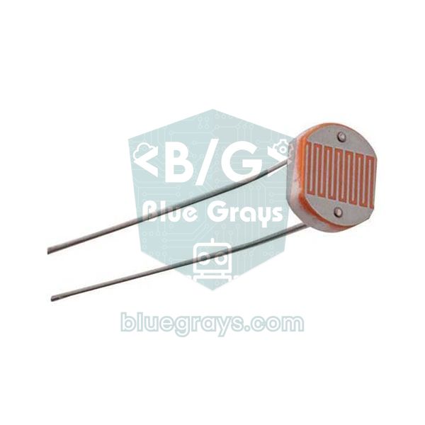
Microcontrollers can't measure resistance directly, only voltage. When you put a resistive sensor such as an LDR or an NTC in series with a fixed resistor to form a voltage divider, the change in resistance becomes a change in voltage at the midpoint. The value of the fixed resistor sets the sensitivity. To get the largest voltage swing, the fixed resistor should be the geometric mean of the sensor's smallest and largest resistance over the range you care about: R = √(Rmin × Rmax). For an LDR that reads 1 kΩ in bright light and 100 kΩ in dim light, that gives √(1 k × 100 k) = 10 kΩ. At 5 V, with 10 kΩ the output swings over 4.09 V, while with 1 kΩ or 100 kΩ the swing shrinks to 2.45 V. That's why starter kits come with 10 kΩ resistors. There's another bonus: because the divider and the ADC run from the same 5 V, the calculated resistance doesn't depend on the supply voltage (a ratiometric measurement), so the code below doesn't even need a Vref value.
1// LDR ve NTC'yi gerilim bölücüyle okuma / Reading an LDR and an NTC with voltage dividers
2// A0: 5V -> LDR -> A0 -> 10k -> GND
3// A1: 5V -> 10k -> A1 -> NTC 10k (B = 3950) -> GND
4const float R_FIXED = 10000.0;  // sabit dirençler (ohm) / fixed resistors (ohms)
5const float R0 = 10000.0;       // NTC'nin 25 °C direnci / NTC resistance at 25 °C
6const float BETA = 3950.0;      // NTC B katsayısı / NTC beta coefficient
7const float T0 = 298.15;        // 25 °C kelvin cinsinden / 25 °C in kelvin
8
9void setup() {
10  Serial.begin(9600);
11}
12
13void loop() {
14  analogRead(A0);                         // kanal değişti, ilk okumayı at / channel changed, discard first reading
15  int ldrRaw = analogRead(A0);
16  analogRead(A1);
17  int ntcRaw = analogRead(A1);
18  if (ldrRaw < 1) ldrRaw = 1;             // sıfıra bölmeyi önle / avoid division by zero
19
20  // Oransal ölçüm: besleme gerilimi hesaptan düşer / ratiometric: the supply voltage cancels out
21  float rLdr = R_FIXED * (1024.0 / ldrRaw - 1.0);
22  float rNtc = R_FIXED * ntcRaw / (1024.0 - ntcRaw);
23  float tempC = 1.0 / (1.0 / T0 + log(rNtc / R0) / BETA) - 273.15;  // Beta denklemi / Beta equation
24
25  Serial.print(F("LDR: "));
26  Serial.print(rLdr / 1000.0, 1);
27  Serial.print(F(" kOhm   NTC: "));
28  Serial.print(rNtc / 1000.0, 2);
29  Serial.print(F(" kOhm   "));
30  Serial.print(tempC, 1);
31  Serial.println(F(" C"));
32  delay(1000);
33}
In the code the LDR sits on top, so the reading rises as the light gets brighter; its resistance is R = 10 kΩ × (1024 / ADC − 1). The NTC sits at the bottom, and as the temperature rises its resistance, and so the voltage read, falls. For the common NTCs rated 10 kΩ at 25 °C with a B coefficient of 3950, the temperature comes from the Beta equation: 1 / T = 1 / T0 + ln(R / R0) / B (temperatures in kelvin). Because the fixed resistor matches the NTC's resistance at 25 °C, the output at room temperature is exactly half the supply, which is where the sensitivity is highest. For better accuracy over a wide temperature range, we cover the Steinhart-Hart equation and the NTC's self-heating in the NTC thermistor guide.
Voltage divider project ideas
- Battery monitor and low-battery alarm: watch the battery in a camper or a solar setup and sound a buzzer when it drops below 11.8 V; for powering options in battery projects, see Running an Arduino on Batteries.
- Digital voltmeter: show the voltage you measure on an LCD or OLED display; the steps are in Building an Arduino Voltmeter.
- Automatic night light: use an LDR divider to switch on LEDs or a relay when it gets dark.
- Solar tracker: compare the voltages of two LDR dividers to turn a panel towards the light (solar tracker).
- Five buttons on one pin: build a ladder of different resistors and work out which button is pressed from the analog value (wiring buttons).
- Thermostat: measure temperature with an NTC divider and switch a fan or heater through a relay at the temperature you set.
Common mistakes and how to fix them
| Symptom | Likely cause | Fix |
|---|---|---|
| Readings are meaningless and keep jumping | The source's negative isn't connected to the Arduino's GND | Connect a common GND |
| Pin voltage is much higher than expected | R1 and R2 are swapped | The larger resistor goes on the source side (top); measure with a multimeter before connecting |
| Reading is 5–10% off the real value | 5% resistors, or Vref isn't 5.00 V | Use 1% metal film resistors and calibrate with VREF and CAL in the code |
| Output drops when a module is connected | Loading effect: the load is in parallel with R2 | Make the load at least 100 × Rth, use smaller resistors or an op-amp buffer |
| Reading drifts with a high-value divider | The ADC's sampling capacitor can't charge fully | Add a 100 nF capacitor at the pin and discard the first reading |
| ESP32 reading stops working when Wi-Fi starts | The divider is on an ADC2 pin | Use GPIO 32–39 (ADC1) |
| Battery drains even when the device is off | The divider draws current from the battery all the time | Connect the divider after the switch and use high-value resistors |
| A module powered from the divider doesn't work | A divider isn't a power supply | Use a regulator such as a 7805, AMS1117 or LM2596 |
| I2C doesn't work through a divider | A divider is one-way, I2C is bidirectional | Use a MOSFET logic level converter |
A voltage divider is just two resistors and one formula, yet it turns up somewhere in almost every project that measures something. Choose the ratio with the formula, choose the absolute values by balancing current against output resistance, account for the loading effect and calibrate the result with a multimeter, and you'll get reliable readings. You can read the background on analog readings in What Is an ADC?. In the BlueGrays app you'll find projects such as reading light intensity with an LDR, an LDR night light, a digital voltmeter with an LCD, temperature measurement with an NTC and an ESP32 HC-SR04 distance meter, each explained step by step with circuit diagrams and code.
Frequently asked questions
What is the voltage divider formula?
The output voltage is Vout = Vin × R2 / (R1 + R2), where R1 is the resistor on the source side and R2 the one on the ground side. For example, dividing 9 V with 10 kΩ and 10 kΩ gives 4.5 V. The formula is only exact when no current is drawn from the output.
Can I use a voltage divider to get 5 V from 12 V?
For measurement or a signal, yes: with 22 kΩ and 10 kΩ you can bring 12 V down to 3.75 V and read it with an Arduino analog input. To power a board or module, no; the output collapses as soon as the load draws current. For power, use a regulator such as the 7805 or a buck converter such as the LM2596.
Which resistors do I need to convert 5 V to 3.3 V?
The most common pair is 1 kΩ on the signal side and 2 kΩ on the ground side, which turns 5 V into 3.33 V. You get the same ratio with 10 kΩ and 20 kΩ, but smaller values are better for fast signals. If you don't have 2 kΩ, 2.2 kΩ and 3.3 kΩ give 3.0 V, which the ESP32 and Pico still read as HIGH.
How do I choose resistor values for a voltage divider?
First set the ratio from the highest input voltage and the pin's limit, then pick R2 (usually 10 kΩ) and calculate R1. If the total resistance is low, the divider wastes current; if it's very high, the loading effect and ADC errors grow. On an Arduino, an output resistance below 10 kΩ, and in battery projects a total of around 100 kΩ, is a good balance.
How do I measure 12 V with an Arduino?
Connect the battery's positive terminal through 22 kΩ to A0, A0 through 10 kΩ to GND, and the battery's negative terminal to the Arduino's GND. In the code, multiply the analogRead() value by 5 / 1024 to get the pin voltage, then multiply that by 3.2 to get the battery voltage. With this divider you can safely measure up to 16 V.
Does a voltage divider drain the battery?
Yes, a divider constantly draws I = Vin / (R1 + R2). A 32 kΩ divider draws 0.375 mA at 12 V, about 9 mAh a day: nothing for a car battery but significant for a small one. In battery projects, use resistors around 100 kΩ with a 100 nF capacitor at the analog pin, or connect the divider after the device's switch.
Projects to build after reading this
See all projects
Measuring Light Intensity with an LDR
Want to see how bright your room is as a number? The LDR, a small part that reacts to light, measures the light around it, and the Arduino writes the value to your computer screen every half second. C

Night Light with Ldr
A little night light that turns on by itself when it gets dark and goes off when morning comes. A light sensor measures how bright the room is, and the Arduino switches the LED on when it is dark enou

Reading Light Intensity with the ESP32 LDR Module
Real-time monitoring of the LDR module's raw ADC value and relative light percentage calculated from dark and light reference values in the Serial Monitor. This percentage is not a lux measurement. Teaches the module’s calibration logic. It is ideal to complete this before Project 10, as it is used to determine the threshold value.
Digital Voltmeter with LCD Display
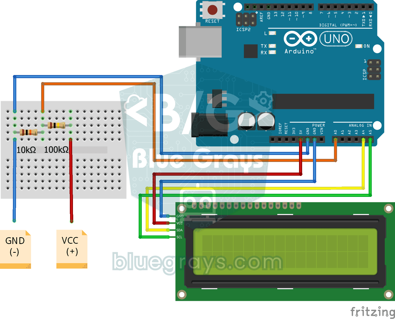
Find out how much voltage a battery or power adapter gives with a meter you built yourself. A divider made of two resistors brings high voltage down to a level the board can read, and the Arduino calc
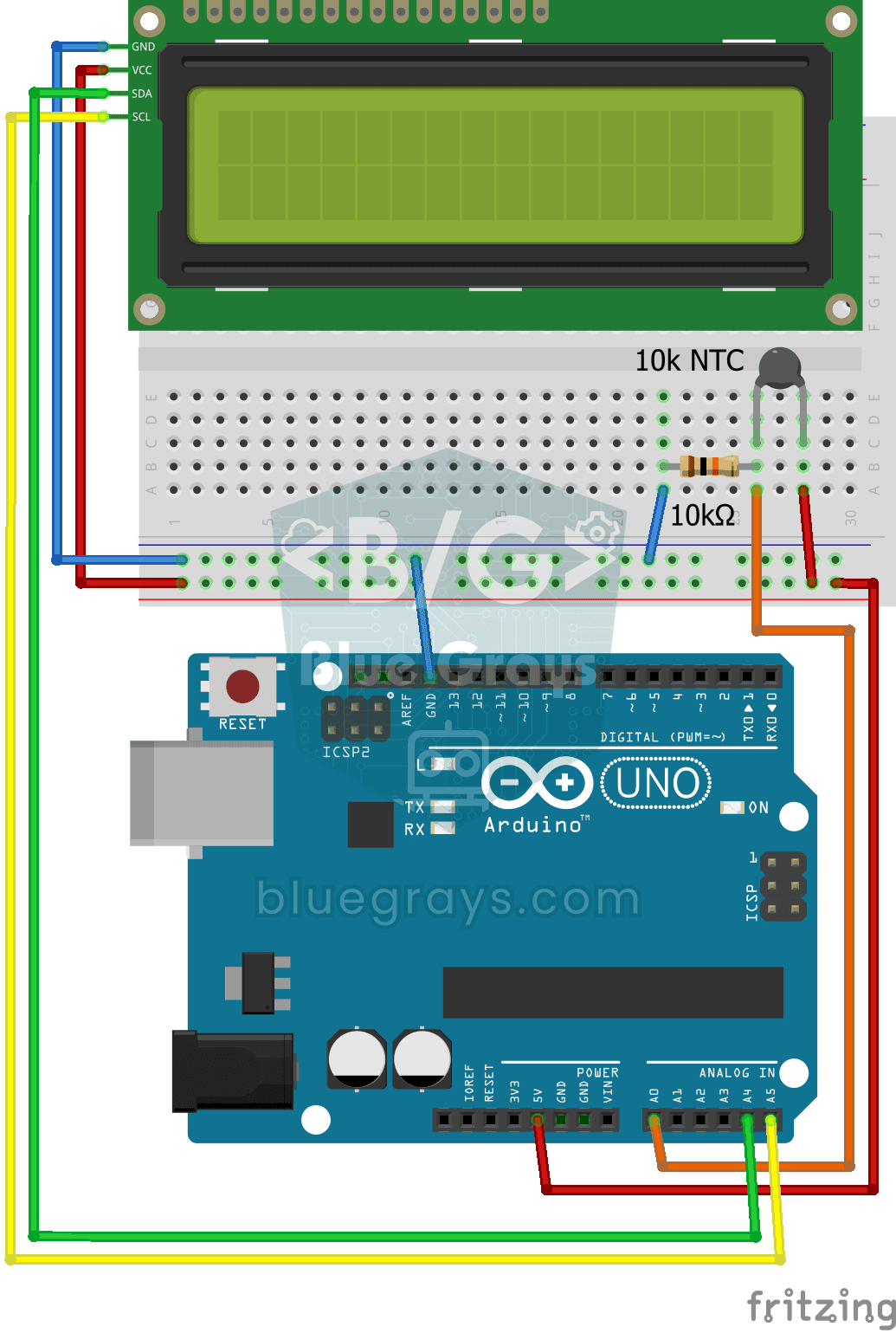
Temperature Measurement with NTC and 2x16 Lcd Display
Measure the temperature around you with a sensor that looks like a tiny bead. This part, called an NTC, lets electricity through more easily as it warms up; the Arduino reads that change, turns it int

ESP32 Night Light with LDR
Night light where the LED automatically turns on in the dark and off in the light. The D0 (digital out) pin of the LDR Sensor Module is used - the dark threshold is set with the small potentiometer on the module, the module itself generates the HIGH/LOW output. ESP32 just reads this signal with digitalRead(), the code is very simple.

ESP32 HC-SR04 Ultrasonic Distance Sensor
The HC-SR04 ultrasonic sensor calculates distance by measuring the time it takes for the sound wave it emits to bounce off an object and return (Time of Flight). In this project, we will send a 10-microsecond pulse from the ESP32 to the sensor's TRIG pin and read the echo duration from the ECHO pin using pulseIn(). We will display the calculated distance in centimeters on a 16x2 I2C LCD. Since the HC-SR04 operates at 5V, a voltage divider is required on the ECHO pin—otherwise, the ESP32’s

ESP32 LED Brightness Control with a Potentiometer (Analog → PWM)
In this project, we control the brightness of an LED analogically using a potentiometer. The ESP32's ADC pin reads the 0-3.3V voltage from the potentiometer, and this value is then converted into a PWM (Pulse Width Modulation) signal and sent to the LED. As a result, as you turn the potentiometer, the LED gradually brightens and dims. With Arduino Core 3.0+, analogWrite() can be used directly; on the ESP32-S2/S3, the ADC resolution is fixed at 12-bit.