
What Is SPI? MOSI, MISO, SCK and CS Pins Explained for Arduino
What is SPI and how does it work? MOSI, MISO, SCK and CS pins, SPI modes and speed, multiple devices, Uno, Mega, ESP32 and Pico pins, SD card + RFID clash.
SPI (Serial Peripheral Interface) is a communication method that lets a microcontroller exchange data very quickly with devices such as SD cards, RFID readers, colour TFT displays or wireless modules over four wires. There's a clock line (SCK), two separate lines for data in each direction (MOSI and MISO) and a CS line that selects which device is being talked to. Because it can be dozens of times faster than I2C, it's the bus of choice for modules that move large amounts of data.
In this post you'll learn how SPI works, the pin names and the newer naming, the four SPI modes, the speed limits, the pins on the Arduino Uno, Mega, ESP32 (VSPI and HSPI) and Raspberry Pi Pico, how to connect several devices to the same bus and why an SD card and an RC522 RFID reader cause trouble together. In the last section we compare SPI with I2C and UART.
What is SPI and how does it work?
SPI always has one controller (formerly called master) and one or more peripherals (formerly called slaves). Only the controller generates the clock; in other words, the Arduino starts the conversation, sets its speed and ends it. On every clock pulse the controller sends one bit on MOSI while, at the same time, the peripheral sends one bit back on MISO. The shift registers on both sides form a kind of ring: after 8 clock pulses the controller's byte has moved into the peripheral and the peripheral's byte into the controller. That's why SPI is full duplex: reading and writing happen at the same time.
| Line | Old name | New name | Direction | Role |
|---|---|---|---|---|
| SCK / SCLK | Serial Clock | SCK | Controller → peripheral | Clock signal; one bit moves on each pulse |
| MOSI | Master Out Slave In | COPI / SDO | Controller → peripheral | Data from the Arduino to the module |
| MISO | Master In Slave Out | CIPO / SDI | Peripheral → controller | Data from the module back to the Arduino |
| CS / SS | Slave Select | CS (Chip Select) | Controller → peripheral | That module listens while it's LOW; each device gets its own CS |
The labels on modules aren't always the same, and this is the biggest source of confusion. On the RC522 RFID module the CS line is labelled SDA (it has nothing to do with I2C's SDA), on the nRF24L01 it's CSN, on the MCP3008 CS/SHDN, and on some displays you'll see names like DIN (MOSI), CLK (SCK) and DOUT (MISO). The rule is simple: the data input (DIN, SDI, MOSI) goes to the Arduino's MOSI and the data output (DOUT, SDO, MISO) goes to the Arduino's MISO.
- The controller pulls the CS line of the device it wants to talk to LOW. All other devices keep their CS HIGH and release the MISO line.
- The controller starts generating clock pulses on SCK.
- On each pulse one bit goes out on MOSI and one bit comes in on MISO. The bit order is usually most significant bit first (MSB first).
- Once the required number of bytes (command, address, data) has been transferred, the controller sets CS back HIGH and the device completes the operation.
SPI modes: CPOL and CPHA
SPI has no single standard; devices differ in the level the clock rests at when idle (CPOL, clock polarity) and the clock edge on which data is read (CPHA, clock phase). The four combinations of these two settings make up the four SPI modes. If the controller and the device aren't in the same mode, the data shifts by one bit and you read meaningless values. Luckily, the vast majority of modules use Mode 0.
| Mode | CPOL | CPHA | Clock when idle | Edge data is read on | Example devices |
|---|---|---|---|---|---|
| SPI_MODE0 | 0 | 0 | LOW | Rising | SD card, RC522, nRF24L01, MAX7219, MCP3008, 74HC595 |
| SPI_MODE1 | 0 | 1 | LOW | Falling | Some ADC and driver chips |
| SPI_MODE2 | 1 | 0 | HIGH | Falling | Rarely used |
| SPI_MODE3 | 1 | 1 | HIGH | Rising | ADXL345 accelerometer, some ST7789 displays without a CS pin |
SPI speed and cable length
In SPI the controller sets the speed and the limit is usually the device itself. The Arduino Uno can go up to 8 MHz, half of its 16 MHz clock; the SPI library's default is 4 MHz. The ESP32 can generate up to 80 MHz on its own SPI pins (IO_MUX), and the limit drops when the signal is routed to other pins through the GPIO matrix. The Raspberry Pi Pico can reach about 62.5 MHz with a 125 MHz system clock. Fast SPI signals need short wires: with a breadboard and 10–20 cm jumper wires a few MHz is no problem; at 20–30 MHz and above keep the wires short and use soldered connections if you can. Lengths of several metres aren't suitable for SPI.
| Device | Role | Maximum SPI clock (datasheet) | SPI mode |
|---|---|---|---|
| MicroSD card | Data logging | 400 kHz at start-up, then up to 25 MHz | Mode 0 |
| RC522 (MFRC522) | RFID reader | 10 MHz | Mode 0 |
| nRF24L01 | 2.4 GHz wireless | 10 MHz | Mode 0 |
| MAX7219 | LED matrix / 7-segment | 10 MHz | Mode 0 |
| MCP3008 | 8-channel 10-bit ADC | 3.6 MHz at 5 V, 1.35 MHz at 2.7 V | Mode 0 or 3 |
| ILI9341 | 2.4–3.2 inch colour TFT | 10 MHz for writes (driven much faster in practice) | Mode 0 |
SPI pins: Arduino Uno, Mega, ESP32 and Raspberry Pi Pico
| Line | Arduino Uno / Nano | Arduino Mega | ESP32 VSPI (default) | ESP32 HSPI | Raspberry Pi Pico SPI0 |
|---|---|---|---|---|---|
| SCK | D13 | D52 | GPIO 18 | GPIO 14 | GP18 |
| MOSI | D11 | D51 | GPIO 23 | GPIO 13 | GP19 (TX) |
| MISO | D12 | D50 | GPIO 19 | GPIO 12 | GP16 (RX) |
| CS (default) | D10 | D53 | GPIO 5 | GPIO 15 | GP17 |
| Logic level | 5 V | 5 V | 3.3 V | 3.3 V | 3.3 V |
On the Uno the same SPI lines are also on the 6-pin ICSP header at the edge of the board; on boards like the Leonardo and Micro, SPI is only available on ICSP. D10 isn't mandatory for CS; you can use any digital pin. However, on the Uno don't leave D10 as an input: if the SPI hardware reads LOW on D10 while it's an input, it drops out of controller mode. SPI.begin() makes this pin an output automatically, and you shouldn't turn it into an input for another job. On the ESP32 the Arduino SPI object uses VSPI by default; thanks to the GPIO matrix you can also move SPI to almost any pins you like. On the Pico, SPI0 and SPI1 can be assigned to several different pin groups (e.g. GP10, GP11, GP12 for SPI1); see the Pinout tool for details.
The Arduino SPI library: basic functions
| Function | What does it do? |
|---|---|
| SPI.begin() | Starts the SPI hardware; makes the SCK, MOSI and SS pins outputs. |
| SPISettings(speed, MSBFIRST, SPI_MODE0) | Holds a device's speed, bit order and mode in one object. |
| SPI.beginTransaction(settings) | Applies the settings and reserves the bus for this device; makes switching between devices with different settings safe. |
| SPI.transfer(byte) | Sends one byte and returns the byte received at the same time. |
| SPI.transfer16(value) | Sends and receives a 16-bit value in one go. |
| SPI.transfer(buffer, length) | Sends an array; the received bytes overwrite the same array. |
| SPI.endTransaction() | Releases the bus; called after setting CS HIGH. |
First example: sending data to a 74HC595 over SPI
The easiest way to understand SPI is with a 74HC595 shift register, because the 595 is really the simplest SPI peripheral, one without MISO. The Arduino's MOSI pin goes to the 595's DS input, SCK to SH_CP, and D10 to ST_CP, which acts as the latch. Unlike the shiftOut() function, hardware SPI sends the byte in a few microseconds:
1// Donanım SPI ile 74HC595: 8 LED'i iki kabloyla sürmek / 74HC595 over hardware SPI: 8 LEDs from two data wires
2// D11 (MOSI) -> DS (14), D13 (SCK) -> SH_CP (11), D10 -> ST_CP / latch (12)
3#include <SPI.h>
4
5const int LATCH_PIN = 10;     // 595'te CS gibi davranır / acts like CS on the 595
6
7void write595(byte value) {
8  SPI.beginTransaction(SPISettings(4000000, MSBFIRST, SPI_MODE0));  // 4 MHz, mod 0 / 4 MHz, mode 0
9  digitalWrite(LATCH_PIN, LOW);
10  SPI.transfer(value);                 // 8 biti gönder / shift out 8 bits
11  digitalWrite(LATCH_PIN, HIGH);       // yükselen kenarda çıkışlara aktar / latch on the rising edge
12  SPI.endTransaction();
13}
14
15void setup() {
16  pinMode(LATCH_PIN, OUTPUT);
17  digitalWrite(LATCH_PIN, HIGH);
18  SPI.begin();
19}
20
21void loop() {
22  for (int i = 0; i < 8; i++) {        // yürüyen ışık / running light
23    write595(1 << i);
24    delay(100);
25  }
26}
Reading data over SPI: the MCP3008 ADC
To see full-duplex communication, let's use the MCP3008. This chip adds 8 more 10-bit analog inputs to the Arduino; it's a good alternative to the ESP32's non-linear ADC or the Pico's mere 3 analog inputs. We covered the basics of analog reading in the What is an ADC? post. Wiring: CLK → D13, DOUT → D12, DIN → D11, CS → D10, VDD and VREF → 5V, AGND and DGND → GND.
1// MCP3008 (8 kanal, 10 bit ADC) okuma / Reading an MCP3008 (8-channel 10-bit ADC)
2// D13 -> CLK, D12 <- DOUT, D11 -> DIN, D10 -> CS/SHDN
3#include <SPI.h>
4
5const int CS_PIN = 10;
6SPISettings mcpSettings(1000000, MSBFIRST, SPI_MODE0);   // 1 MHz, mod 0 / 1 MHz, mode 0
7
8int readMCP3008(byte channel) {
9  SPI.beginTransaction(mcpSettings);
10  digitalWrite(CS_PIN, LOW);                   // cihazı seç / select the chip
11  SPI.transfer(0x01);                          // başlangıç biti / start bit
12  byte high = SPI.transfer(0x80 | (channel << 4));   // tek uçlu + kanal / single-ended + channel
13  byte low = SPI.transfer(0x00);               // kalan 8 bit / remaining 8 bits
14  digitalWrite(CS_PIN, HIGH);                  // seçimi bırak / release the chip
15  SPI.endTransaction();
16  return ((high & 0x03) << 8) | low;           // 10 bitlik sonuç / 10-bit result
17}
18
19void setup() {
20  Serial.begin(9600);
21  pinMode(CS_PIN, OUTPUT);
22  digitalWrite(CS_PIN, HIGH);                  // başta seçili değil / not selected at start
23  SPI.begin();
24}
25
26void loop() {
27  int raw = readMCP3008(0);
28  float volts = raw * 5.0 / 1023.0;
29  Serial.print("CH0: ");
30  Serial.print(raw);
31  Serial.print("  ");
32  Serial.print(volts, 2);
33  Serial.println(" V");
34  delay(500);
35}
Here we send three bytes and receive three bytes at the same time. The first byte (0x01) is just the start bit; the second byte carries single-ended mode and the channel number, while the MCP3008 sends back the top 2 bits of the result. The third byte is 0x00; its content doesn't matter, it's only sent to generate clock pulses and receive the remaining 8 bits of the result. In SPI, "reading" always means sending something. The result is between 0 and 1023 and is converted to volts relative to VREF (5 V here).
Several SPI devices: separate CS lines
SPI's biggest difference from I2C is that it doesn't use addresses. Devices share the SCK, MOSI and MISO lines, and each one gets its own CS wire from the Arduino. Only the device whose CS is LOW listens, and only that device writes data onto MISO. Three devices need 3 + 3 = 6 wires, five devices 3 + 5 = 8 wires; the pin count grows with the number of devices. Some chips such as the 74HC595 and MAX7219 can be daisy-chained instead: the output of one goes into the input of the next and they're all driven with a single CS.
- Only one CS should be LOW at a time. If two devices are selected together they collide on the MISO line and you read corrupted data from both.
- In setup(), first make every CS pin an output and pull it HIGH, then start the libraries. A floating CS pin can randomly look LOW and grab the bus.
- Use beginTransaction for each device. An SD card may want 25 MHz and an MCP3008 1 MHz; transactions apply the right speed and mode automatically on every switch.
- If you use SPI inside interrupts, tell the library with SPI.usingInterrupt(), or don't do SPI work inside the interrupt.
- Adding a 10 kΩ pull-up on each device's CS line stops devices from selecting themselves while the Arduino boots or resets.
SD card and RFID on the same bus: why doesn't it work?
A classic question on Arduino forums: the RC522 RFID works on its own, the SD card module works on its own, but when both are on the same SPI bus one or both go silent. Even when the CS pins are right in software, the problem is usually in the hardware. Many cheap SD card modules have a 74LVC125 buffer chip that converts 5 V signals to 3.3 V, and the channel of this chip that drives the MISO line is always enabled. So even when the SD card's CS is HIGH, the module doesn't let go of MISO; when the RC522 tries to answer, the line is fought over by two outputs.
- Choose the right module: modules that put MISO into high impedance when CS is HIGH share the bus without trouble. You can tell whether a module releases the line by pulling MISO through 10 kΩ first to GND and then to 5 V with CS HIGH and measuring with a multimeter.
- Tie the buffer's enable pin to CS: if you're comfortable soldering, lifting the OE pin of the 74LVC125's MISO channel from GND and connecting it to the module's CS line fixes the problem for good.
- Add a series resistor on MISO: putting a series resistor of about 1 kΩ on the SD module's MISO output lets the RC522 overpower the line. It's an easy but speed-limiting stopgap.
- Use a separate SPI bus: on the ESP32, if you connect the SD card to VSPI and the RC522 to HSPI, the two devices never meet. The Uno has no second hardware SPI, so this option doesn't exist there.
- Watch the start-up order: first set all CS pins HIGH, then call SPI.begin(), then SD.begin() and PCD_Init(). The example below follows this order.
1// Aynı SPI hattında SD kart ve RC522 RFID / SD card and RC522 RFID on the same SPI bus
2// Ortak / shared: D11 MOSI, D12 MISO, D13 SCK. CS: SD -> D4, RC522 SDA(SS) -> D10, RC522 RST -> D9
3#include <SPI.h>
4#include <SD.h>
5#include <MFRC522.h>
6
7const int SD_CS = 4;
8const int RFID_CS = 10;
9const int RFID_RST = 9;
10
11MFRC522 rfid(RFID_CS, RFID_RST);
12
13void setup() {
14  Serial.begin(9600);
15  // Önce TÜM CS pinlerini HIGH yap: hiçbir cihaz hattı meşgul etmesin
16  // First drive ALL CS pins HIGH so no device grabs the bus
17  pinMode(SD_CS, OUTPUT);
18  digitalWrite(SD_CS, HIGH);
19  pinMode(RFID_CS, OUTPUT);
20  digitalWrite(RFID_CS, HIGH);
21
22  SPI.begin();
23  if (!SD.begin(SD_CS)) {
24    Serial.println(F("SD bulunamadi / SD not found"));
25  }
26  rfid.PCD_Init();
27  Serial.println(F("Karti okut / Scan a card"));
28}
29
30void loop() {
31  if (!rfid.PICC_IsNewCardPresent() || !rfid.PICC_ReadCardSerial()) return;
32
33  String uid = "";
34  for (byte i = 0; i < rfid.uid.size; i++) {
35    if (rfid.uid.uidByte[i] < 0x10) uid += "0";
36    uid += String(rfid.uid.uidByte[i], HEX);
37  }
38  rfid.PICC_HaltA();
39
40  File f = SD.open("kartlar.txt", FILE_WRITE);   // kütüphane CS'yi kendisi yönetir / the library handles CS itself
41  if (f) {
42    f.print(millis());
43    f.print(";");
44    f.println(uid);
45    f.close();
46    Serial.println("Kaydedildi / Saved: " + uid);
47  } else {
48    Serial.println(F("Dosya acilamadi / File open failed"));
49  }
50}
In this code the SD library and the MFRC522 library drive their own CS pins LOW and HIGH; all you have to do is leave both HIGH at the start and make sure the hardware shares MISO properly. The code writes the UID of every scanned card, together with a timestamp, to the kartlar.txt file. On the Uno these two libraries together use about half the RAM; the F() macro frees up space by keeping constant strings in flash.
VSPI and HSPI on the ESP32: two separate SPI buses
The ESP32 has four SPI units inside; SPI0 and SPI1 are reserved for the internal flash memory, which leaves VSPI (SPI3) and HSPI (SPI2) for you. Using both is the cleanest way to separate devices with very different speeds and modes or to escape the MISO clash above. In the Arduino core you create an SPIClass object for the second bus and give it its pins with begin(). The code below runs the SD card on the default VSPI and the MCP3008 on HSPI, and appends a reading to a CSV file every second:
1// ESP32: iki ayrı SPI hattı / two separate SPI buses
2// VSPI (varsayılan SPI / default SPI): SD kart / SD card -> SCK 18, MISO 19, MOSI 23, CS 5
3// HSPI: MCP3008 -> SCK 14, MISO 12, MOSI 13, CS 15
4#include <SPI.h>
5#include <SD.h>
6
7const int SD_CS = 5;
8const int ADC_CS = 15;
9
10SPIClass hspi(HSPI);                              // ikinci donanım SPI / second hardware SPI
11SPISettings mcpSettings(1000000, MSBFIRST, SPI_MODE0);
12
13int readMCP3008(byte channel) {
14  hspi.beginTransaction(mcpSettings);
15  digitalWrite(ADC_CS, LOW);
16  hspi.transfer(0x01);
17  byte high = hspi.transfer(0x80 | (channel << 4));
18  byte low = hspi.transfer(0x00);
19  digitalWrite(ADC_CS, HIGH);
20  hspi.endTransaction();
21  return ((high & 0x03) << 8) | low;
22}
23
24void setup() {
25  Serial.begin(115200);
26  pinMode(ADC_CS, OUTPUT);
27  digitalWrite(ADC_CS, HIGH);
28  hspi.begin(14, 12, 13, ADC_CS);                 // SCK, MISO, MOSI, SS
29
30  if (!SD.begin(SD_CS)) {                         // SD varsayılan VSPI'yi kullanır / SD uses the default VSPI
31    Serial.println("SD bulunamadi / SD not found");
32  }
33}
34
35void loop() {
36  int raw = readMCP3008(0);
37  File f = SD.open("/olcum.csv", FILE_APPEND);    // ekle kipinde aç / open in append mode
38  if (f) {
39    f.printf("%lu,%d\n", millis(), raw);
40    f.close();
41  }
42  Serial.printf("CH0: %d\n", raw);
43  delay(1000);
44}SPI with the Raspberry Pi Pico (MicroPython)
The Pico has two hardware SPI units (SPI0 and SPI1), used in MicroPython through the machine.SPI class. The polarity and phase parameters correspond to CPOL and CPHA; if both are 0 it's Mode 0. You manage CS yourself as an ordinary output pin. The write_readinto() function shows SPI's full-duplex nature best: while sending one array, it writes the incoming bytes into another. Let's read the same MCP3008, this time powered from 3.3 V:
1# Raspberry Pi Pico: SPI0 ile MCP3008 okuma / reading an MCP3008 on SPI0
2# GP18 -> CLK, GP19 -> DIN (MOSI), GP16 <- DOUT (MISO), GP17 -> CS. MCP3008 VDD ve VREF 3V3 / VDD and VREF on 3V3
3from machine import Pin, SPI
4import time
5
6spi = SPI(0, baudrate=1_000_000, polarity=0, phase=0,   # mod 0 / mode 0
7          sck=Pin(18), mosi=Pin(19), miso=Pin(16))
8cs = Pin(17, Pin.OUT, value=1)                          # başta seçili değil / not selected at start
9
10def read_mcp3008(channel):
11    tx = bytearray([0x01, 0x80 | (channel << 4), 0x00])
12    rx = bytearray(3)
13    cs.value(0)                                          # cihazı seç / select the chip
14    spi.write_readinto(tx, rx)                           # aynı anda gönder ve al / send and receive at once
15    cs.value(1)
16    return ((rx[1] & 0x03) << 8) | rx[2]
17
18while True:
19    raw = read_mcp3008(0)
20    print("CH0:", raw, "{:.2f} V".format(raw * 3.3 / 1023))
21    time.sleep(0.5)
SPI vs I2C vs UART
| Feature | SPI | I2C | UART |
|---|---|---|---|
| Number of wires | 4 (+1 CS for each extra device) | 2 (SDA, SCL) | 2 (TX, RX) |
| Typical speed | 1–80 MHz | 100 kHz, 400 kHz, 1 MHz | 9600–115200 baud (up to a few Mbit/s) |
| Clock | Yes (generated by the controller) | Yes (generated by the controller) | None; both sides agree on the same baud rate |
| Direction | Full duplex | Half duplex | Full duplex |
| Device selection | Separate CS wire | 7-bit address | Only two devices (point to point) |
| Extra parts | None needed | Pull-up resistors | None needed |
| Distance | Short (on-board, a few tens of cm) | Short (around 1 m) | A few metres; much longer with RS-485 |
| Typical modules | SD card, RC522, TFT, nRF24L01, MAX7219 | OLED, I2C LCD backpack, RTC, BME280, MPU6050 | GPS, HC-05, SIM800L, ESP-01, computer |
The choice is usually made by the module, but in your own designs this rule helps: if speed and data volume matter (display images, files, audio) use SPI; if you need few wires and many slow sensors, use I2C; if you want a simple, text-based link between two devices, use UART. You'll find UART in detail in the UART serial communication post. Using all three in the same project is also very common: for example a data logger that reads sensors over I2C, writes to an SD card over SPI and gets its position from a GPS over UART.
Modules that use SPI and project ideas
- Card door lock and access log: read the card with an RC522 and write the date and UID to an SD card.
- Temperature logger: record sensor data to a microSD card as CSV and plot it in Excel.
- Scrolling text board: show the time and messages on daisy-chained MAX7219 LED matrix modules.
- Colour interface: draw graphics and menus on an ILI9341 TFT display; connect the touch panel to the same SPI bus too.
- Wireless remote: send commands to your robot car with two nRF24L01 modules.
- Multi-channel measurement: build a MIDI controller with 8 potentiometers or an irrigation system with 8 soil moisture sensors using an MCP3008.
Common mistakes and how to fix them
| Symptom | Likely cause | Fix |
|---|---|---|
| Always reading 0xFF or 0x00 | MISO not connected, MOSI and MISO swapped, or the device has no power | Connect DIN to MOSI and DOUT to MISO; measure the device's VCC |
| Values are nonsense or shifted by one bit | Wrong SPI mode or a clock too fast for the device | Use the mode from the datasheet, drop the speed to 1 MHz and try again |
| Two devices that work alone don't work together | One module doesn't release MISO, or the CS pins aren't HIGH at start | Set all CS pins HIGH first; replace the module that won't release MISO or use a separate SPI bus |
| SPI suddenly stops on the Uno | D10 was used as an input and pulled LOW | Leave D10 as an output; you can use it as a CS |
| ESP32 won't boot with HSPI connected | GPIO 12 is held HIGH at boot | Move the pulled-up MISO to VSPI or choose another pin for MISO |
| Random errors on long wires | Reflections and noise on a fast signal | Shorten the wires, lower the speed, run a GND wire alongside the signals |
SPI is the common language of the Arduino world's fast modules, from SD cards to colour displays: once you've learned the four wires, the CS logic and the four modes, hooking up a new SPI module takes a few minutes. In the BlueGrays app you'll find the RFID card reading and door lock, microSD temperature logger and MAX7219 dot matrix clock projects, step by step with circuit diagrams and code.
Frequently asked questions
What does SPI stand for?
SPI stands for Serial Peripheral Interface. It lets a controller exchange data quickly and synchronously with peripherals over four lines: SCK, MOSI, MISO and CS.
What are MOSI and MISO?
MOSI (Master Out Slave In) is the data line from the controller to the peripheral; MISO (Master In Slave Out) is the data line from the peripheral back to the controller. In the newer naming they're also called COPI and CIPO. On modules, DIN usually goes to MOSI and DOUT to MISO.
Which are the SPI pins on the Arduino Uno?
On the Arduino Uno and Nano, SCK is D13, MISO is D12, MOSI is D11 and the default CS is D10. The same lines are also on the board's 6-pin ICSP header. On the Arduino Mega, SCK is D52, MISO D50, MOSI D51 and CS D53.
What is the difference between SPI and I2C?
SPI uses four wires, is full duplex and can run at tens of MHz; each device needs its own CS wire. I2C uses only two wires and selects devices by address, but runs at much lower speeds such as 100–400 kHz and needs pull-up resistors.
How many devices can be connected to one SPI bus?
There's no theoretical limit; all you need is a free CS pin on the controller for each device. In practice, problems appear at high speeds as the bus capacitance and wire length grow. If you run out of pins, you can multiply the CS lines with a 74HC138 decoder or use devices that can be daisy-chained.
Why don't an SD card and an RFID reader work on the same SPI bus?
The level shifter on many cheap SD card modules doesn't release the MISO line even when CS is HIGH, and it corrupts the RC522's answer. Using a module that releases MISO properly, tying the buffer chip's enable pin to CS, or putting the two devices on separate SPI buses on the ESP32 solves it.
Projects to build after reading this
See all projects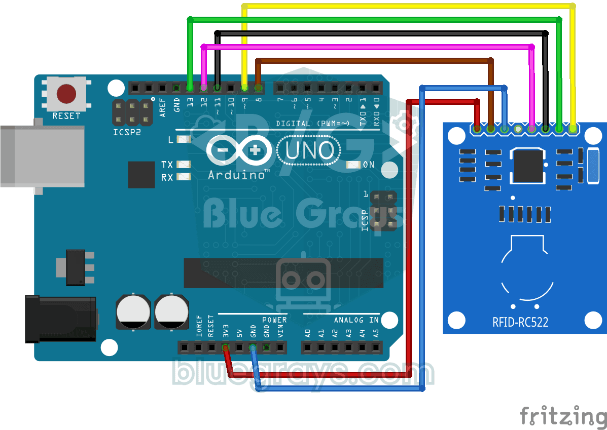
RFID Value Reading
Your building key fob or access card hides a secret ID number, and this project reads it. Hold the card near the RFID reader and the Arduino writes the card's number to your computer screen. The first
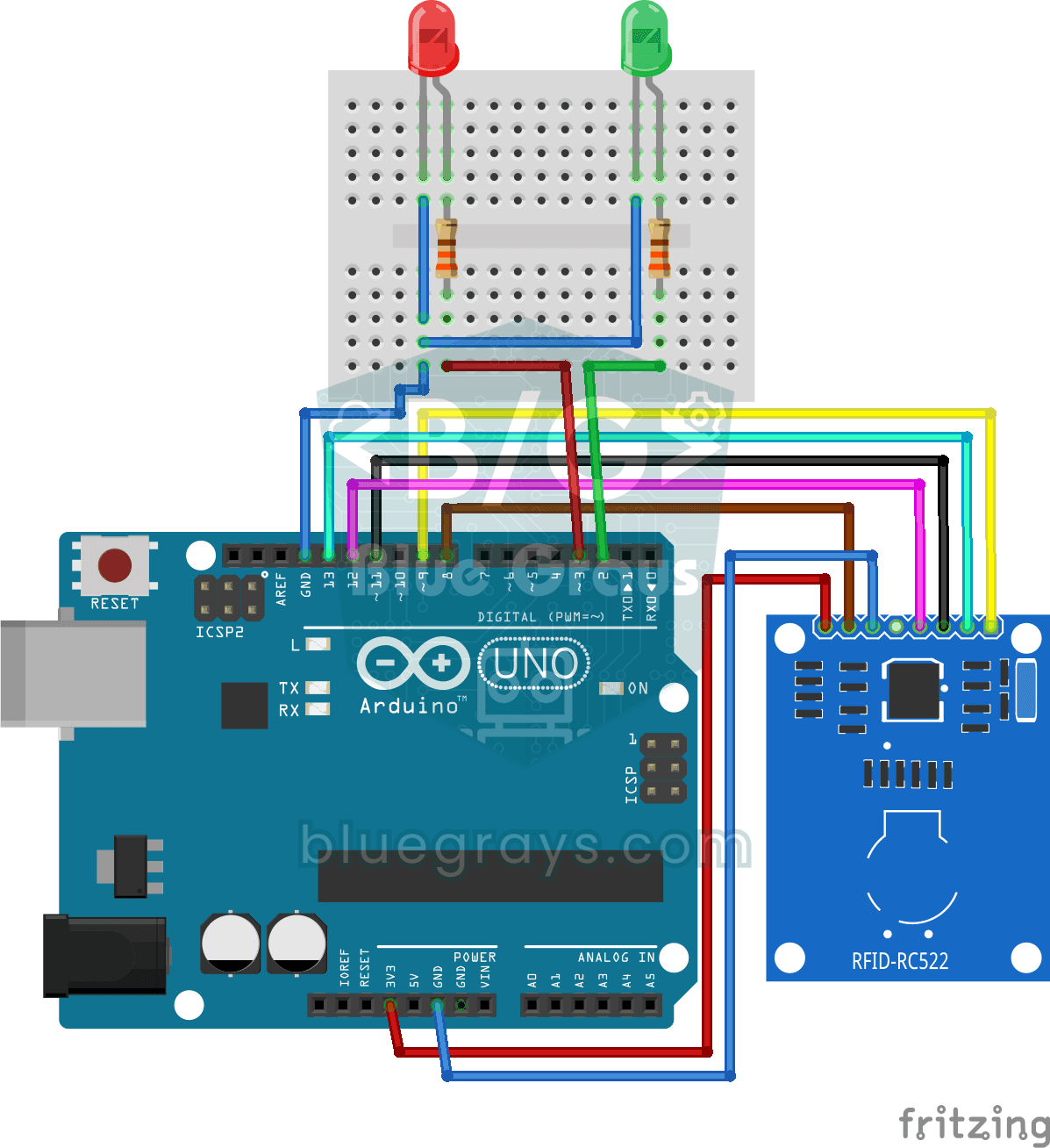
RFID Authentication
Just like the card entry at an apartment door: you hold your card near the RFID reader, and the Arduino compares its number with the one it has saved. The right card lights the green LED for three sec

ESP32 RFID RC522 Card Reader (with LCD)
In this project, we will connect the MFRC522-based RC522 RFID module to the ESP32 via SPI and read the card/tag UID. This forms the basis for applications such as door locks, membership systems, and access control. We will display the read UID on an LCD screen; this version does not compare it with an authorized card list. WARNING: The RC522 operates only at 3.3V; supplying 5V will burn out the module!

ESP32 RFID Door Lock (RC522 + Servo + OLED + Buzzer + LED)
We’re building a smart door lock using an ESP32, an RC522 RFID module, an SG90 servo motor, an SSD1306 OLED display, an active buzzer, and 2 LEDs. When a card is scanned, its UID is compared to the list of authorized cards stored in the code—if authorized, the servo motor rotates to unlock the door (green LED + 2 short beeps), and the door automatically locks again after 5 seconds. For an unauthorized card, the red LED lights up, a warning is given with 3 rapid beeps, and the captured UID is dis
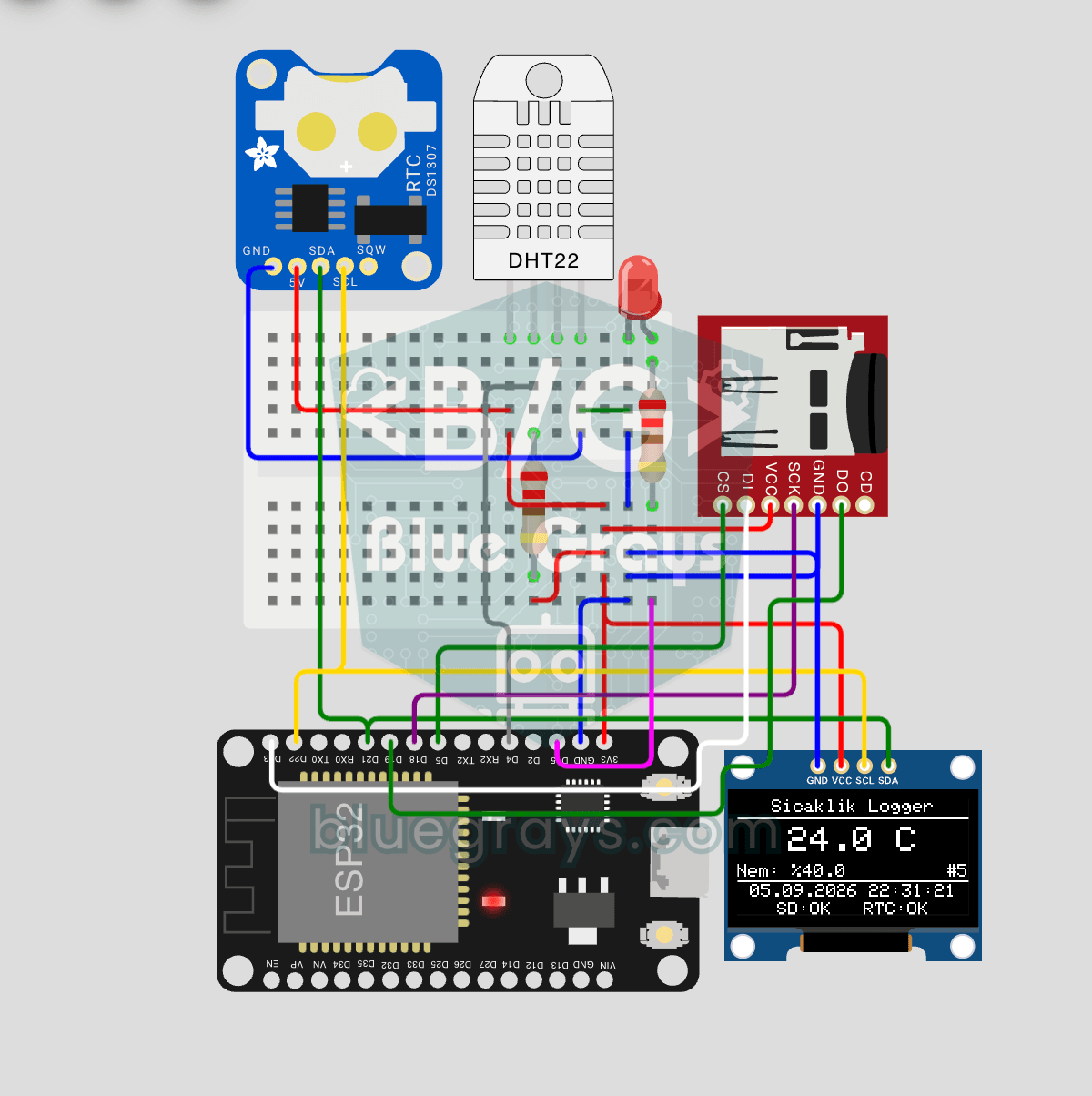
ESP32 Temperature Data Logger (DHT22 + DS1307 RTC + microSD + OLED)
Build a timestamped temperature logger with ESP32! Read DHT22 temperature/humidity every minute, get real-world time from DS1307 RTC, and log to microSD card as CSV. The OLED displays live temperature (large font), humidity percentage, timestamp, and log counter. The /temp_log.csv file on the SD card opens in Excel, Google Sheets, or Python pandas for analysis — perfect for greenhouse monitoring, home/room temperature tracking, laboratory data collection, food storage conditions, or beehiv

Dot Matrix Clock and Calendar (MAX7219, DS1307)
A glowing board for your desk or wall that shows the time and date in scrolling text. The 8x32 LED display holds a big-digit clock whose two dots blink every second; at the start of each minute the da

4x 32x8 Matrix LED Animation and Text
Stack four long LED matrix modules on top of each other and you get a square screen with more than a thousand dots of light. First, letters pour down from the top like rain in the movies, then a curta

Pixel Snake 8x8 Matrix
Build the classic snake game with your own hands and play it. On a colorful 8x8 light matrix, you steer a green snake with a joystick and eat red apples; with every apple the snake grows, speeds up a