
ILI9341 Arduino Guide: TFT Display Wiring, Touch and SD Images
How to connect an ILI9341 TFT display to Arduino: 3.3 V level shifting on the Uno, Adafruit GFX, XPT2046 touch, BMP from SD, ESP32 TFT_eSPI, white screen fix.
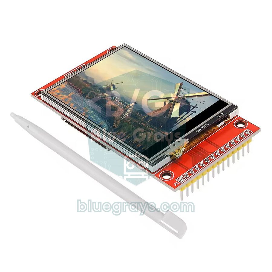
An ILI9341 Arduino setup is the cheapest and most popular way to add a 240×320-pixel display with 65 thousand colours to your project. These 2.4- and 2.8-inch TFT modules on a red PCB connect over SPI with just a few wires, and the touch versions also carry an XPT2046 touch controller and a microSD card slot. With a single module you can show colour graphics, touch buttons and pictures read from a card. It's ideal for menus, dashboards, games and photo frames where an OLED or a character LCD is no longer enough.
In this guide you'll learn step by step how the module works, how to safely connect the Arduino Uno's 5 V outputs to the display's 3.3 V inputs, how to draw text, shapes and colours with the Adafruit_ILI9341 and Adafruit GFX libraries, how to read the touchscreen and how to show BMP images from an SD card. After that we'll cover much faster drawing on the ESP32 with TFT_eSPI, using MicroPython on the Raspberry Pi Pico, and every cause of the "white screen" problem that almost everyone runs into at least once.
What is the ILI9341 TFT display and how does it work?
The ILI9341 is the driver chip behind the glass. It contains about 172 KB of display memory (GRAM) that holds all 240×320 pixels. The Arduino sends commands and colour data to this memory over SPI, and the chip refreshes the picture on its own dozens of times per second. That's why the image doesn't have to live in the Arduino's RAM: even a Uno with 2 KB of RAM can drive a large colour screen. To draw something, you first select a window (x, y, width, height) and then send that window's pixels one after another. The DC pin tells the chip whether the byte being sent is a command (LOW) or data (HIGH). Colours are usually sent in RGB565 format, which means 16 bits per pixel: 5 bits red, 6 bits green and 5 bits blue. You'll find how the SPI bus works in detail in What is SPI.
| Feature | Value |
|---|---|
| Driver chip | ILI9341 |
| Resolution | 240×320 pixels (320×240 in landscape) |
| Colour | 65,536 colours with RGB565 (the chip supports 262K) |
| Screen sizes | 2.2", 2.4", 2.8" and 3.2" (all 240×320) |
| Interface | 4-wire SPI: CS, DC, SCK, MOSI (MISO for reading) |
| Supply (VCC) | 3.3–5 V (there is a 3.3 V regulator on the board) |
| Logic level | 3.3 V (not 5 V tolerant) |
| Power consumption | About 0.3–0.6 W, mostly the backlight |
| Touch | Resistive, XPT2046 controller (on touch models) |
| Extra hardware | microSD card slot (separate SPI pins) |
2.4 inch or 2.8 inch? SPI module vs. Uno shield
| Feature | 2.4" SPI module | 2.8" SPI module | 2.4" Uno shield |
|---|---|---|---|
| Resolution | 240×320 | 240×320 | 240×320 |
| Connection | SPI, with jumper wires | SPI, with jumper wires | 8-bit parallel, plugs on top of the Uno |
| Pins used | 5 for the display, 8–9 with touch and SD | 5 for the display, 8–9 with touch and SD | Almost all (D2–D9, A0–A4, D10–D13 for SD) |
| Driver | ILI9341 | ILI9341 | Varies: ILI9341, ILI9325, ST7789 and others |
| Library | Adafruit_ILI9341, TFT_eSPI | Adafruit_ILI9341, TFT_eSPI | MCUFRIEND_kbv |
| Touch | XPT2046 (SPI) | XPT2046 (SPI) | 4-wire analog (TouchScreen library) |
| ESP32 and Pico | Suitable | Suitable | Designed for the Uno and Mega |
This article covers the SPI module, because it also works with the ESP32 and Pico and leaves most of the Uno's pins free. The two SPI modules have exactly the same pins and code; the 2.8-inch screen has slightly larger pixels, so touch buttons are easier to hit. If your display plugs straight on top of the Uno as a shield, the SPI libraries can't drive it, and the result is usually a white screen. For a shield like that, install the MCUFRIEND_kbv library, read the driver ID with tft.readID() (0x9341 for the ILI9341) and start it with tft.begin(ID). For a smaller but sharper alternative see ST7789 TFT display, and to compare every option read Arduino display types.
ILI9341 pinout and wiring table
One edge of the module has the 14-pin main header: the first 9 pins are for the display and the last 5, starting with T_, are for touch. The 4 pins on the opposite edge (SD_CS, SD_MOSI, SD_MISO, SD_SCK) go to the card slot. All three devices can share the same SPI bus (SCK, MOSI, MISO); only their CS pins must be separate. The table below matches every sketch in this article; on the Pico, touch is wired to a separate SPI bus because of the speed difference.
| Module pin | Arduino Uno (via level shifter) | ESP32 | Raspberry Pi Pico |
|---|---|---|---|
| VCC | 5V | 3V3 | 3V3(OUT) |
| GND | GND | GND | GND |
| CS | D10 | GPIO 15 | GP17 |
| RESET | D8 | GPIO 4 | GP21 |
| DC | D9 | GPIO 2 | GP20 |
| SDI (MOSI) | D11 | GPIO 23 | GP19 |
| SCK | D13 | GPIO 18 | GP18 |
| LED | 3.3V | 3V3 | 3V3(OUT) |
| SDO (MISO) | D12 (direct) | GPIO 19 | GP16 |
| T_CLK | D13 | GPIO 18 | GP10 |
| T_CS | D7 | GPIO 21 | GP13 |
| T_DIN | D11 | GPIO 23 | GP11 |
| T_DO | D12 (direct) | GPIO 19 | GP12 |
| T_IRQ | D2 (direct) | Not connected | Not connected |
| SD_CS | D4 | GPIO 5 | Not connected |
| SD_MOSI / SD_MISO / SD_SCK | D11 / D12 / D13 | GPIO 23 / 19 / 18 | Not connected |
3.3 V level shifting on the Arduino Uno
The ESP32 and Raspberry Pi Pico already run at 3.3 V, so you can connect the display directly. On 5 V boards such as the Uno, Nano and Mega, every line going from the Arduino to the display must be brought down to 3.3 V: CS, DC, RESET, SCK, MOSI and, if you use touch and SD, T_CLK, T_DIN, T_CS, SD_CS, SD_MOSI and SD_SCK. The SDO, T_DO, SD_MISO and T_IRQ lines coming from the display to the Arduino don't need a converter: the Uno reads anything above 3 V as HIGH, and a 3.3 V output meets that. In practice there are four ways to do it:
- 74HC4050 buffer chip (the cleanest solution): it runs from 3.3 V, accepts 5 V on its inputs and converts 6 lines in one chip. It's fast and works without problems at 8 MHz SPI. The older CD4050 also works but is slow; if the picture gets corrupted you'll need to lower the SPI speed. The display alone needs 5 lines; with touch and SD you add T_CS and SD_CS for 7 lines, so use a second chip or a voltage divider for the seventh.
- Resistor voltage dividers: for each line, put 1 kΩ between the Arduino pin and the display pin and 2 kΩ between the display pin and GND; that gives 5 V × 2 / 3 ≈ 3.3 V. You can work out other resistor pairs with the voltage divider calculator. It's cheap, but 10 resistors for 5 lines make the breadboard crowded.
- Ready-made level shifter module: 4- or 8-channel modules with BSS138 MOSFETs are easy to wire, but their pull-up resistors soften the signal edges at high speeds. If the picture gets corrupted, drop SPI to 4 MHz with tft.begin(4000000). The methods are compared in logic level converter.
- The method to avoid: the popular "10 kΩ series resistor on every line" trick dumps the excess voltage into the chip's internal protection diodes. It may work for a while, but it's unreliable and can damage the display in the long run.
Step by step: first test with Adafruit_ILI9341
- Open the Library Manager in the Arduino IDE, search for Adafruit ILI9341 and install it. When it asks about dependencies, choose Install all so that Adafruit GFX and Adafruit BusIO are installed too. If this is your first library, How to add an Arduino library will help.
- For touch, also install Paul Stoffregen's XPT2046_Touchscreen library. The SD library comes with the Arduino IDE.
- Wire the display according to the table above, through a level shifter on the Uno. For the first test you can leave the touch and SD pins unconnected.
- Upload the sketch below and open the Serial Monitor at 9600 baud. You should see text and shapes on the display and the display's diagnostic codes in the Serial Monitor.
- Try the bundled examples too: File > Examples > Adafruit ILI9341 > graphicstest measures how many microseconds each drawing operation takes.
1#include <SPI.h>
2#include <Adafruit_GFX.h>
3#include <Adafruit_ILI9341.h>
4
5#define TFT_CS  10   // ekran seçme / chip select
6#define TFT_DC  9    // komut/veri seçimi / command/data select
7#define TFT_RST 8    // donanım reset / hardware reset
8
9Adafruit_ILI9341 tft(TFT_CS, TFT_DC, TFT_RST);   // donanım SPI: D11 MOSI, D13 SCK / hardware SPI
10uint16_t orange;                                  // kendi rengimiz / our own colour
11
12void setup() {
13  Serial.begin(9600);
14  tft.begin();                                    // Uno'da 8 MHz SPI / 8 MHz SPI on Uno
15
16  // Teşhis: çalışan ekranda 0x94 ve 0xC0 beklenir / Diagnostics: a working display reports 0x94 and 0xC0
17  Serial.print(F("Power Mode: 0x"));
18  Serial.println(tft.readcommand8(ILI9341_RDMODE), HEX);
19  Serial.print(F("Self Diagnostic: 0x"));
20  Serial.println(tft.readcommand8(ILI9341_RDSELFDIAG), HEX);
21
22  tft.setRotation(1);                             // yatay, 320x240 / landscape, 320x240
23  tft.fillScreen(ILI9341_BLACK);
24  orange = tft.color565(255, 128, 0);             // RGB'den RGB565'e / RGB to RGB565
25
26  tft.setTextColor(ILI9341_WHITE);
27  tft.setTextSize(3);                             // 18x24 piksel karakter / 18x24 px characters
28  tft.setCursor(10, 10);
29  tft.print(F("BlueGrays"));
30  tft.setTextColor(ILI9341_CYAN);
31  tft.setTextSize(2);
32  tft.setCursor(10, 45);
33  tft.print(F("ILI9341 320x240"));
34
35  tft.fillRect(10, 75, 90, 60, ILI9341_RED);                  // dolu dikdörtgen / filled rectangle
36  tft.drawRect(115, 75, 90, 60, ILI9341_GREEN);               // çerçeve / outline
37  tft.fillCircle(265, 105, 30, ILI9341_BLUE);                 // dolu daire / filled circle
38  tft.fillRoundRect(10, 150, 140, 50, 10, orange);            // yuvarlak köşeli düğme / rounded button
39  tft.drawTriangle(180, 200, 240, 150, 300, 200, ILI9341_YELLOW);
40  tft.drawFastHLine(0, 220, 320, ILI9341_MAGENTA);            // yatay çizgi / horizontal line
41}
42
43void loop() {
44  // Arka plan rengiyle yazınca eski rakam silinir, ekran titremez / writing with a background colour erases the old digits, no flicker
45  tft.setTextColor(ILI9341_WHITE, orange);
46  tft.setTextSize(2);
47  tft.setCursor(22, 167);
48  tft.print(millis() / 1000);
49  tft.print(F(" s"));
50  delay(200);
51}| Function | What it does |
|---|---|
| tft.begin(frequency) | Starts the display; without a frequency it uses 8 MHz SPI on the Uno and 40 MHz on the ESP32 |
| tft.setRotation(0–3) | Selects the orientation: 0 and 2 portrait (240×320), 1 and 3 landscape (320×240) |
| tft.fillScreen(colour) | Paints the whole screen in one colour |
| tft.setTextColor(text, background) | Sets the text colour; with a background colour it overwrites the old text cleanly |
| tft.setTextSize(n) | Scales the text n times; size 1 = 6×8-pixel characters |
| tft.drawRect / fillRect(x, y, width, height, colour) | Rectangle outline or filled rectangle |
| tft.fillRoundRect(x, y, width, height, r, colour) | Filled rectangle with rounded corners; ideal for buttons |
| tft.drawCircle / fillCircle(x, y, r, colour) | Circle or filled circle |
| tft.color565(r, g, b) | Converts 0–255 RGB values into a 16-bit colour |
| tft.readcommand8(command) | Reads a register from the display (MISO must be connected); for troubleshooting |
Ready-made colour constants (19 of them, such as ILI9341_RED, ILI9341_NAVY and ILI9341_ORANGE) come with the library; for your own colour use color565(). It packs the top 5 bits of red, the top 6 bits of green and the top 5 bits of blue side by side: colour = (R >> 3) << 11 | (G >> 2) << 5 | (B >> 3). For orange (255, 165, 0), for example, 31 << 11 = 0xF800 and 41 << 5 = 0x0520 combine into 0xFD20, which is exactly the library's ILI9341_ORANGE value. Green gets one extra bit because the human eye is more sensitive to green.
Reading the XPT2046 touchscreen
On touch modules there is a thin resistive layer on top of the glass. Where your finger or a stylus presses, two conductive layers touch; the XPT2046 chip measures the X and Y position of that point with a 12-bit ADC as raw values from 0 to 4095 and also reports a pressure value (Z). The library treats a Z value below 400 as no touch. The chip sits on the same SPI bus as the display but talks at a lower speed, around 2 MHz; the library sets the speed itself on every read. The T_IRQ pin goes LOW when the screen is touched, which saves the processor from pointless reads. The sketch below turns the screen into a small drawing board: you pick a colour from the boxes at the top and clear the screen with the "SIL" (clear) button.
1#include <SPI.h>
2#include <Adafruit_GFX.h>
3#include <Adafruit_ILI9341.h>
4#include <XPT2046_Touchscreen.h>
5
6#define TFT_CS  10
7#define TFT_DC  9
8#define TFT_RST 8
9#define T_CS    7    // dokunmatik seçme / touch chip select
10#define T_IRQ   2    // dokununca LOW olur / goes LOW on touch
11#define SD_CS   4    // SD kullanılmıyor, HIGH tutulur / SD unused, kept HIGH
12
13// Kalibrasyon: Seri Monitör'deki ham değerlerle değiştir / Calibration: replace with the raw values from Serial Monitor
14#define TS_MINX 300
15#define TS_MAXX 3800
16#define TS_MINY 300
17#define TS_MAXY 3800
18
19Adafruit_ILI9341 tft(TFT_CS, TFT_DC, TFT_RST);
20XPT2046_Touchscreen ts(T_CS, T_IRQ);
21
22uint16_t brush = ILI9341_YELLOW;                  // fırça rengi / brush colour
23
24void drawPalette() {
25  tft.fillRect(0, 0, 40, 40, ILI9341_RED);
26  tft.fillRect(40, 0, 40, 40, ILI9341_GREEN);
27  tft.fillRect(80, 0, 40, 40, ILI9341_BLUE);
28  tft.fillRect(120, 0, 40, 40, ILI9341_YELLOW);
29  tft.drawRect(260, 0, 60, 40, ILI9341_WHITE);    // silme düğmesi / clear button
30  tft.setTextColor(ILI9341_WHITE);
31  tft.setTextSize(2);
32  tft.setCursor(273, 13);
33  tft.print(F("SIL"));
34}
35
36void setup() {
37  Serial.begin(9600);
38  pinMode(SD_CS, OUTPUT);
39  digitalWrite(SD_CS, HIGH);                      // SD kart hattı meşgul etmesin / keep the SD card off the bus
40  tft.begin();
41  tft.setRotation(1);                             // ekran yatay / display landscape
42  ts.begin();
43  ts.setRotation(1);                              // dokunmatik de aynı yönde / touch in the same orientation
44  tft.fillScreen(ILI9341_BLACK);
45  drawPalette();
46}
47
48void loop() {
49  if (!ts.touched()) return;                      // dokunma yok / no touch
50  TS_Point p = ts.getPoint();                     // ham x, y (0-4095) ve basınç z / raw x, y and pressure z
51  Serial.print(p.x); Serial.print(',');
52  Serial.print(p.y); Serial.print(',');
53  Serial.println(p.z);
54
55  int16_t x = constrain(map(p.x, TS_MINX, TS_MAXX, 0, 319), 0, 319);   // ekran koordinatı / screen coordinate
56  int16_t y = constrain(map(p.y, TS_MINY, TS_MAXY, 0, 239), 0, 239);
57
58  if (y < 40) {                                   // üst şerit: palet ve düğme / top strip: palette and button
59    if (x < 40)        brush = ILI9341_RED;
60    else if (x < 80)   brush = ILI9341_GREEN;
61    else if (x < 120)  brush = ILI9341_BLUE;
62    else if (x < 160)  brush = ILI9341_YELLOW;
63    else if (x >= 260) { tft.fillScreen(ILI9341_BLACK); drawPalette(); }
64  } else {
65    tft.fillCircle(x, y, 3, brush);               // parmağın altına nokta / dot under the finger
66  }
67}
The raw values are not 0 and 4095 at the very corners; on most modules the edges sit roughly between 200–400 and 3700–3900. To calibrate, open the Serial Monitor, touch the top-left and bottom-right corners with a stylus and enter the x and y values you see into the TS_MINX, TS_MAXX, TS_MINY and TS_MAXY constants. If the dot appears mirrored from your finger, swap that axis's min and max values in map(); if X and Y are completely swapped, try ts.setRotation() values from 0 to 3. A real menu works the same way: you draw buttons and check which rectangle the touched point falls into. The resistive layer works with a finger too, but a stylus-like tip is more accurate for small buttons.
Showing BMP images from the SD card
The microSD slot on the back of the module lets you keep logos, backgrounds and photos on a card and show them on the screen. To prepare an image, resize a photo to 320×240 pixels and save it in Paint as a 24-bit Bitmap (.bmp). Because the Arduino SD library works with short file names, use a name of up to 8 characters such as RESIM.BMP and format the card as FAT32. Details about the card itself and the fix for the initialization failed error are in Arduino SD card module. Remember that this slot is 3.3 V too: on the Uno, the SD_CS, SD_MOSI and SD_SCK lines must also go through the level shifter.
1#include <SPI.h>
2#include <SD.h>
3#include <Adafruit_GFX.h>
4#include <Adafruit_ILI9341.h>
5
6#define TFT_CS  10
7#define TFT_DC  9
8#define TFT_RST 8
9#define SD_CS   4
10#define T_CS    7
11#define CHUNK   20   // tek okumada 20 piksel (60 bayt) / 20 pixels (60 bytes) per read
12
13Adafruit_ILI9341 tft(TFT_CS, TFT_DC, TFT_RST);
14
15uint16_t read16(File &f) {                        // BMP sayıları küçük uçlu / BMP numbers are little-endian
16  uint16_t lo = f.read();
17  uint16_t hi = f.read();
18  return lo | (hi << 8);
19}
20
21uint32_t read32(File &f) {
22  uint32_t lo = read16(f);
23  uint32_t hi = read16(f);
24  return lo | (hi << 16);
25}
26
27bool drawBmp(const char *name, int16_t x, int16_t y) {
28  File f = SD.open(name);
29  if (!f) return false;                                   // dosya yok / file not found
30  if (read16(f) != 0x4D42) { f.close(); return false; }  // "BM" imzası / "BM" signature
31  read32(f);                                              // dosya boyutu / file size
32  read32(f);                                              // ayrılmış alan / reserved
33  uint32_t offset = read32(f);                            // piksel verisinin başı / start of pixel data
34  read32(f);                                              // başlık boyutu / header size
35  int32_t w = (int32_t)read32(f);
36  int32_t h = (int32_t)read32(f);
37  read16(f);                                              // düzlem sayısı / colour planes
38  uint16_t depth = read16(f);
39  uint32_t comp = read32(f);
40  if (depth != 24 || comp != 0) { f.close(); return false; }   // yalnız 24 bit, sıkıştırmasız / 24-bit uncompressed only
41
42  bool bottomUp = true;                                   // BMP satırları alttan üste / rows are stored bottom-up
43  if (h < 0) { h = -h; bottomUp = false; }
44  uint32_t rowSize = (w * 3 + 3) & ~3UL;                  // satırlar 4 baytın katı / rows padded to 4 bytes
45  int32_t drawW = w, drawH = h;
46  if (x + drawW > tft.width())  drawW = tft.width() - x;   // ekrana sığmayanı kırp / clip to the screen
47  if (y + drawH > tft.height()) drawH = tft.height() - y;
48
49  uint8_t sdBuf[CHUNK * 3];
50  uint16_t line[CHUNK];
51  for (int32_t row = 0; row < drawH; row++) {
52    uint32_t pos = offset + (bottomUp ? (h - 1 - row) : row) * rowSize;
53    f.seek(pos);                                          // satırın başına git / jump to the start of the row
54    for (int32_t col = 0; col < drawW; col += CHUNK) {
55      int16_t n = drawW - col;
56      if (n > CHUNK) n = CHUNK;
57      f.read(sdBuf, n * 3);
58      for (int16_t i = 0; i < n; i++) {                   // BGR'den RGB565'e / BGR to RGB565
59        line[i] = tft.color565(sdBuf[i * 3 + 2], sdBuf[i * 3 + 1], sdBuf[i * 3]);
60      }
61      tft.drawRGBBitmap(x + col, y + row, line, n, 1);    // parçayı ekrana bas / push the chunk to the screen
62    }
63  }
64  f.close();
65  return true;
66}
67
68void setup() {
69  Serial.begin(9600);
70  pinMode(T_CS, OUTPUT);
71  digitalWrite(T_CS, HIGH);                       // dokunmatik hattı meşgul etmesin / keep touch off the bus
72  tft.begin();
73  tft.setRotation(1);                             // 320x240 yatay / landscape
74  tft.fillScreen(ILI9341_BLACK);
75  tft.setTextSize(2);
76
77  if (!SD.begin(SD_CS)) {                         // kart başlatılamadı / card init failed
78    tft.setTextColor(ILI9341_RED);
79    tft.setCursor(10, 10);
80    tft.print(F("SD kart bulunamadi"));
81    return;
82  }
83  uint32_t t = millis();
84  if (!drawBmp("RESIM.BMP", 0, 0)) {
85    tft.setTextColor(ILI9341_YELLOW);
86    tft.setCursor(10, 10);
87    tft.print(F("RESIM.BMP okunamadi"));
88  }
89  Serial.print(F("Cizim suresi / Draw time (ms): "));
90  Serial.println(millis() - t);
91}
92
93void loop() {
94}
The first 54 bytes of a BMP file are the header: the "BM" signature, where the pixel data starts, the width, the height and the colour depth are stored there. Pixels are stored in blue, green, red (BGR) order and normally bottom to top, and each row is padded to a multiple of 4 bytes. That's why the sketch jumps to the right position in the file for every screen row, reads 20 pixels (60 bytes) at a time, converts them to RGB565 and pushes them with drawRGBBitmap(). Working in small chunks keeps everything within the Uno's RAM and lets the SD card and the display take turns on the same SPI bus. The drawing time is printed to the Serial Monitor; on the Uno a full-screen image appears row by row over a few seconds. If you want to show PNG or JPEG files and draw much faster, move to an ESP32 with the TFT_eSPI and TJpg_Decoder libraries.
Fast drawing on the ESP32 with TFT_eSPI
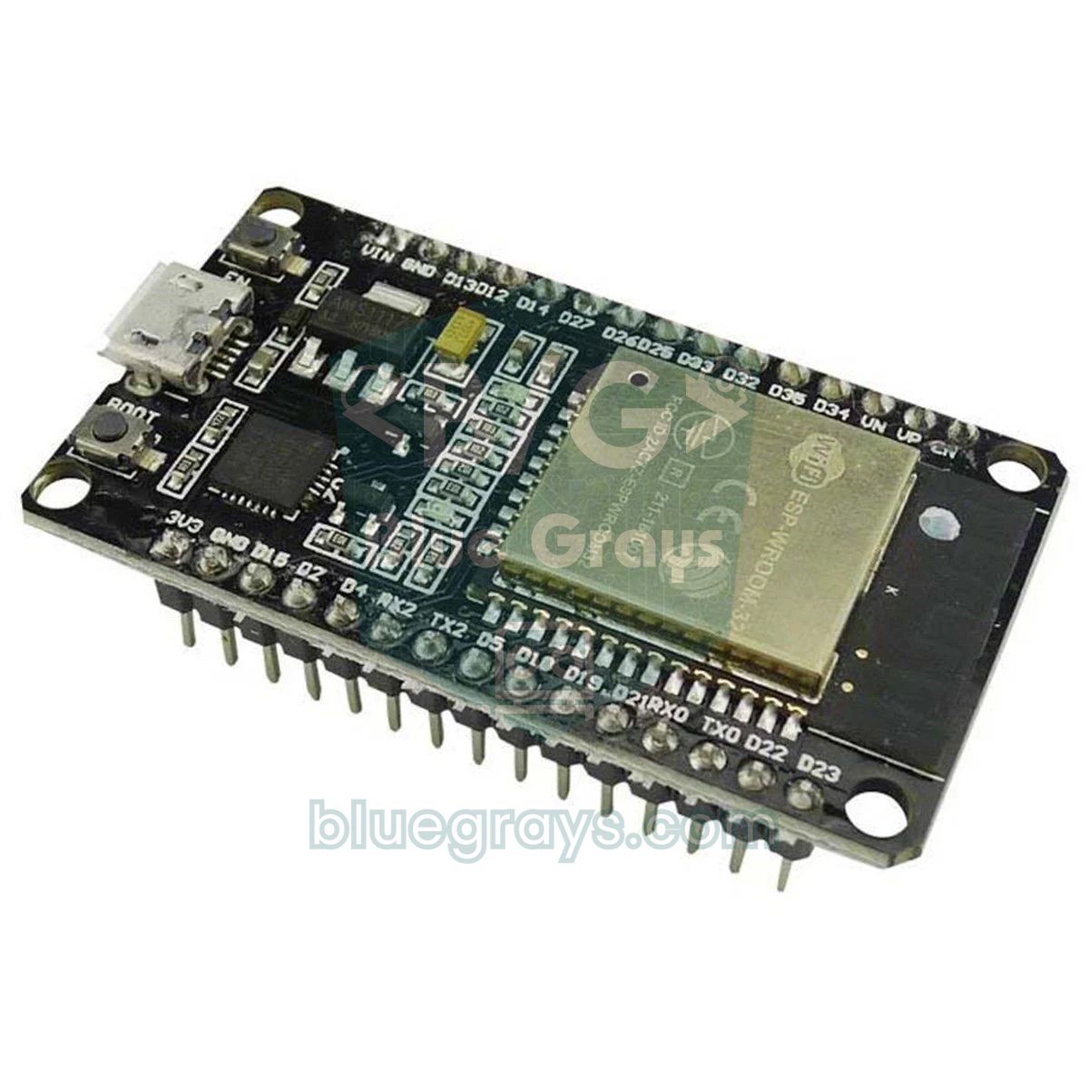
The ESP32 runs at 3.3 V and can drive SPI at up to 40 MHz, so you don't need a level shifter and filling the whole screen drops to about 31 milliseconds in theory. To really use that speed, Bodmer's TFT_eSPI library is the usual choice. It accesses the ESP32's SPI hardware directly and supports anti-aliased (smooth) fonts and, most importantly, off-screen buffers called sprites. You draw as much as you like into a sprite in RAM and send the result to the screen in one go, so even fast-changing graphics don't flicker. What makes TFT_eSPI different is that the pins are not set in your sketch but in the User_Setup.h file inside the library folder. Open it, comment out the ESP8266 (NodeMCU) pin lines that are active by default and enable these:
1// TFT_eSPI/User_Setup.h içinde yalnız bu satırlar açık kalsın / keep only these lines active in TFT_eSPI/User_Setup.h
2#define ILI9341_DRIVER
3
4#define TFT_MISO 19
5#define TFT_MOSI 23
6#define TFT_SCLK 18
7#define TFT_CS   15   // ekran seçme / chip select
8#define TFT_DC    2   // komut/veri / data/command
9#define TFT_RST   4   // sıfırlama / reset
10#define TOUCH_CS 21   // dokunmatik seçme (T_CS) / touch chip select (T_CS)
11
12#define LOAD_GLCD     // 1: 8 piksel yazı tipi / 8 px font
13#define LOAD_FONT2    // 2: 16 piksel / 16 px
14#define LOAD_FONT4    // 4: 26 piksel / 26 px
15#define LOAD_FONT7    // 7: 7 segment rakamlar / 7-segment digits
16#define LOAD_GFXFF    // Adafruit FreeFont'lar / Adafruit FreeFonts
17#define SMOOTH_FONT
18
19#define SPI_FREQUENCY       40000000   // kablolar uzunsa 27000000 / 27 MHz with long wires
20#define SPI_READ_FREQUENCY  20000000
21#define SPI_TOUCH_FREQUENCY 25000001#include <SPI.h>
2#include <TFT_eSPI.h> // pinler User_Setup.h içinde / pins are set in User_Setup.h
3
4TFT_eSPI tft = TFT_eSPI();
5TFT_eSprite graph = TFT_eSprite(&tft); // ekran dışı çizim alanı / off-screen canvas
6
7// Touch_calibrate örneğinin verdiği 5 sayıyla değiştir / replace with the 5 numbers from the Touch_calibrate example
8uint16_t calData[5] = {286, 3534, 283, 3600, 6};
9
10const int GW = 300, GH = 100; // grafik boyutu / graph size
11uint8_t samples[GW]; // son 300 ölçüm / last 300 readings
12uint32_t frames = 0, fps = 0, lastFps = 0;
13
14void setup() {
15 tft.init();
16 tft.setRotation(1); // yatay, 320x240 / landscape, 320x240
17 tft.setTouch(calData);
18 tft.fillScreen(TFT_BLACK);
19 tft.setTextColor(TFT_WHITE, TFT_BLACK);
20 tft.drawString("ESP32 + TFT_eSPI", 10, 8, 4); // 4 numaralı yazı tipi, 26 px / font 4, 26 px
21 graph.createSprite(GW, GH); // 300x100x2 bayt = 60 KB RAM / 60 KB of RAM
22}
23
24void loop() {
25 memmove(samples, samples + 1, GW - 1); // grafiği sola kaydır / scroll the graph left
26 samples[GW - 1] = map(analogRead(34), 0, 4095, 0, GH - 1); // GPIO 34'teki potansiyometre / pot on GPIO 34
27
28 graph.fillSprite(TFT_BLACK);
29 for (int y = 0; y < GH; y += 25) graph.drawFastHLine(0, y, GW, TFT_DARKGREY); // ızgara / grid
30 for (int x = 1; x < GW; x++) {
31 graph.drawLine(x - 1, GH - 1 - samples[x - 1], x, GH - 1 - samples[x], TFT_GREEN);
32 }
33 graph.setTextColor(TFT_YELLOW);
34 graph.drawString(String(fps) + " FPS", 4, 4, 2);
35 graph.pushSprite(10, 50); // tek seferde ekrana gönder, titreme yok / push in one go, no flicker
36
37 uint16_t tx, ty;
38 if (tft.getTouch(&tx, &ty)) { // dokunulduysa / if touched
39 tft.fillRect(10, 170, 300, 30, TFT_BLACK);
40 tft.setTextColor(TFT_CYAN, TFT_BLACK);
41 tft.drawString("Dokunma / Touch: " + String(tx) + ", " + String(ty), 10, 175, 2);
42 }
43
44 frames++;
45 if (millis() - lastFps >= 1000) { // saniyede bir FPS hesapla / compute FPS once per second
46 fps = frames;
47 frames = 0;
48 lastFps = millis();
49 }
50}The sketch draws the value of a potentiometer on GPIO 34 as a scrolling graph and shows the frames per second (FPS) in the corner of the sprite. A 300×100-pixel sprite in 16-bit colour takes 60 KB of RAM; that's about 30 times the Uno's entire memory, but no problem for the ESP32. For touch, the T_CLK, T_DIN and T_DO pins join the display's SCK, MOSI and MISO lines, and only T_CS (GPIO 21) stays separate. To get your own calibration values, run TFT_eSPI's Generic > Touch_calibrate example once, touch the corner arrows that appear and copy the 5 numbers printed in the Serial Monitor into the calData array. The ready-made Setup42_ILI9341_ESP32.h line in User_Setup_Select.h selects the same display pins, but you have to add the TOUCH_CS line to it yourself. If you're new to the ESP32, read What is the ESP32 first.
ILI9341 with the Raspberry Pi Pico and MicroPython
The Pico is a 3.3 V board too, so the display connects directly. The most widely used MicroPython driver is the ili9341.py and xpt2046.py pair from rdagger's micropython-ili9341 repository; just copy both files to the Pico with Thonny. In the code below the display is on SPI0 at 40 MHz and the touch controller is on a separate SPI1 bus at 1 MHz, so the speed difference between the two chips is not a problem. The code draws text and shapes, then puts yellow dots wherever you touch, making a simple drawing board. If you're using the Pico and Thonny for the first time, start with What is the Raspberry Pi Pico.
1from machine import Pin, SPI
2from time import sleep_ms
3from ili9341 import Display, color565      # ili9341.py Pico'da olmalı / must be on the Pico
4from xpt2046 import Touch                  # xpt2046.py Pico'da olmalı / must be on the Pico
5
6# Ekran: SPI0, 40 MHz / Display: SPI0, 40 MHz
7spi_tft = SPI(0, baudrate=40000000, sck=Pin(18), mosi=Pin(19), miso=Pin(16))
8tft = Display(spi_tft, cs=Pin(17), dc=Pin(20), rst=Pin(21), width=240, height=320, rotation=0)
9
10# Dokunmatik: ayrı SPI1, 1 MHz / Touch: separate SPI1, 1 MHz
11spi_touch = SPI(1, baudrate=1000000, sck=Pin(10), mosi=Pin(11), miso=Pin(12))
12touch = Touch(spi_touch, cs=Pin(13), width=240, height=320)
13
14WHITE = color565(255, 255, 255)
15YELLOW = color565(255, 255, 0)
16
17tft.clear(color565(0, 0, 0))                                   # ekranı temizle / clear the screen
18tft.draw_text8x8(10, 10, "BlueGrays + Pico", WHITE)
19tft.fill_rectangle(10, 30, 100, 50, color565(255, 0, 0))       # dolu dikdörtgen / filled rectangle
20tft.draw_rectangle(130, 30, 100, 50, color565(0, 255, 0))      # çerçeve / outline
21tft.fill_circle(60, 130, 30, color565(0, 128, 255))            # dolu daire / filled circle
22tft.draw_line(0, 175, 239, 175, color565(255, 0, 255))         # çizgi / line
23tft.draw_text8x8(10, 185, "Ekrana dokun / Touch me", YELLOW)
24
25while True:
26    raw = touch.raw_touch()                # dokunma yoksa None / None when not touched
27    if raw is not None:
28        x, y = touch.normalize(*raw)       # ham değeri piksele çevir / raw value to pixels
29        y = 319 - y                        # eksen ters ise / if the axis is inverted
30        x = min(max(x, 3), 236)            # ekran dışına taşma / keep inside the screen
31        y = min(max(y, 3), 316)
32        tft.fill_circle(x, y, 3, YELLOW)
33    sleep_ms(20)
In portrait mode (rotation=0) the width is 240 and the height 320; to use the screen in landscape, pass width=320 and height=240 together with rotation=90. The touch driver's default calibration (x_min=100, x_max=1962) may not fit every module; if the dot is off, print the raw_touch() values and pass your own x_min, x_max, y_min and y_max to Touch(). To show pictures, the driver's draw_image() function reads .raw files converted to RGB565; the repository's utils/img2rgb565.py script does that conversion on your computer.
The white screen problem and how to fix it
The most famous ILI9341 problem is a screen that stays completely white while the backlight is on. A white screen is actually a clue: power and backlight are working, but the driver chip was never initialised. When the panel receives no commands, the pixels let the light through and the screen looks white. So the problem is almost always communication. Go through the table below from top to bottom:
| Symptom | Likely cause | Fix |
|---|---|---|
| White screen, wired directly to the Uno | 5 V signals, no level shifter | Use a 74HC4050 or voltage dividers; replace the module if the chip is damaged |
| White screen, wires connected | CS and DC swapped, or the pin numbers in the code don't match the wiring | Compare the TFT_CS, TFT_DC and TFT_RST definitions with the table one by one |
| White screen, RESET floating | RESET not connected or on the wrong pin | Connect RESET to the pin in the code or to 3.3 V; never leave it floating |
| White screen on the ESP32 (TFT_eSPI) | User_Setup.h not edited or wiped by an update | Disable the ESP8266 lines and write the ESP32 pins and ILI9341_DRIVER again |
| Occasional white screen, shifted or garbled picture | Long jumper wires, SPI too fast, loose breadboard contacts | Keep wires under 10–15 cm; lower SPI to 20–27 MHz, or 4 MHz on the Uno |
| White screen only with touch or SD attached | The other device's CS pin is floating and blocks the bus | Set every unused CS pin as OUTPUT and write it HIGH in your code |
| Doesn't work with any code | The display is not an ILI9341 (ST7789, ILI9488) or it's a parallel shield | Read the label on the back; a 3.5-inch 320×480 screen is an ILI9488, a shield needs MCUFRIEND_kbv |
| White screen, flickering backlight | Insufficient power | Power VCC from 5 V and try another USB cable and power supply |
Other common mistakes
- Wrong colours: if red shows up as blue, the panel uses BGR order; change the TFT_RGB_ORDER setting in TFT_eSPI. If the colours look like a negative, try tft.invertDisplay(true).
- Upside-down or mirrored picture: change the setRotation() value between 0 and 3 and adjust the touch axes to match.
- The display works but touch or SD doesn't: check that T_CS and SD_CS match the pins in your code. On some modules the display's SDO output doesn't release the bus; in that case try disconnecting the display's SDO pin, and only the diagnostic read will stop working.
- The BMP doesn't show: the card isn't FAT32, the file name is longer than 8 characters or the image isn't 24-bit. Don't forget to choose 24-bit in Paint; 16- and 32-bit BMPs aren't drawn by this sketch.
- Special characters are missing: the default GFX font has no accented letters such as ş, ğ or é. In TFT_eSPI you can create your own smooth font, or use a GFX font that includes the characters you need.
- The display is slow: a full-screen refresh on the Uno takes at least 0.15 seconds. For animations and games move to an ESP32 or Pico and redraw only the area that changes.
- The module gets hot: 5 V may be on VCC with the J1 jumper closed, or VCC and GND may be reversed; disconnect the power immediately.
ILI9341 project ideas
- Touch smart home panel: control lights and relays with big on-screen buttons; for ideas see Arduino smart home project.
- Colour weather display: show the weather you fetch from the internet with an ESP32 using icons and large digits (ESP32 weather station).
- Sensor dashboard: draw temperature, humidity and pressure from a BME280 as gauges with a graph of the last 24 hours.
- Retro game console: play Snake, Pong or Tetris in colour; add a joystick module for control and check Arduino game projects for ideas.
- Digital photo frame: cycle through the BMP images on the SD card every few seconds.
- Mini oscilloscope: draw analogRead values as a smooth waveform with a sprite on the ESP32.
- Touch keypad lock: draw a number pad on the screen and open a relay or servo when the right code is entered.
The ILI9341 is the most affordable way to give your projects a colour touch interface: start with the Uno to learn the basic drawing functions, then move to the ESP32 with TFT_eSPI when you need speed and smooth animation. If you'd rather start with a smaller screen, OLED display (SSD1306) is a good place to begin. In the BlueGrays app you'll find the ESP32 weather display, temperature logger, parking sensor and display-based game projects with step-by-step circuit diagrams and code.
Frequently asked questions
Does the ILI9341 display work with 5 V?
The module's VCC pin accepts 3.3–5 V because there is a 3.3 V regulator on the board. The signal pins such as CS, DC, SCK and MOSI, however, are 3.3 V only. When you use it with an Arduino Uno, put a level shifter such as a 74HC4050 or voltage dividers on those lines.
Why does my ILI9341 show only a white screen?
A white screen means the backlight is on but the driver chip was never initialised. The most common causes are wrong CS, DC or RESET wiring, no level shifter on the Uno, an unedited User_Setup.h in TFT_eSPI, and a display that isn't actually an ILI9341.
Which library should I use for the ILI9341?
For the Arduino Uno, Nano and Mega, Adafruit_ILI9341 with Adafruit GFX is the easiest choice. On ESP32, ESP8266 and RP2040 boards the much faster TFT_eSPI is preferred. Parallel 2.4-inch shields that plug onto the Uno need MCUFRIEND_kbv instead.
How do I calibrate the ILI9341 touchscreen?
The XPT2046 touch controller returns raw values from 0 to 4095. Note the smallest and largest values you see in the Serial Monitor when you touch the corners and convert them to screen coordinates with map(). If you use TFT_eSPI, the Touch_calibrate example does this for you and prints a ready-made calibration array.
What is the difference between the 2.4 and 2.8 inch ILI9341?
Both have a resolution of 240×320 pixels and use the same pins and code. The 2.8-inch screen has slightly larger pixels, so text is easier to read and touch buttons are easier to press. The 2.4-inch module fits into smaller enclosures.
Can I use the ILI9341 with an Arduino Nano?
Yes. The Nano's SPI pins are the same as the Uno's: D13 SCK, D11 MOSI and D12 MISO. The Nano also uses 5 V logic, so you need a level shifter. Its 2 KB of RAM is enough to drive the display, but not to hold large images, so you have to read pictures from the SD card in small pieces.
Projects to build after reading this
See all projects
ESP32 HTTPClient + Weather API (with SSD1306 OLED Display)
In this project, we use the ESP32 to make a REST API call to a weather API (wttr.in) over the internet using HTTPClient.h. Unlike the previous I2C LCD version, we’re using an SSD1306 OLED (128×64) display here—which allows for large fonts, vector icons, and rich visual presentation on a single screen. Seven different vector icons for weather conditions (sunny, partly cloudy, cloudy, rainy, snowy, stormy, foggy) are drawn at runtime (no bitmap files required). The temperature is displayed in th
ESP32 Temperature Data Logger (DHT22 + DS1307 RTC + microSD + OLED)
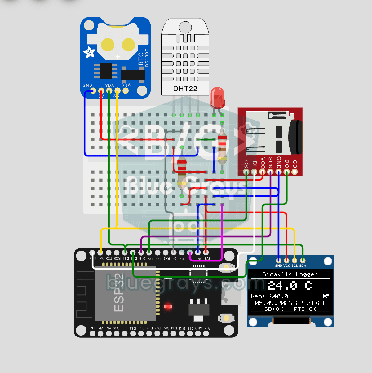
Build a timestamped temperature logger with ESP32! Read DHT22 temperature/humidity every minute, get real-world time from DS1307 RTC, and log to microSD card as CSV. The OLED displays live temperature (large font), humidity percentage, timestamp, and log counter. The /temp_log.csv file on the SD card opens in Excel, Google Sheets, or Python pandas for analysis — perfect for greenhouse monitoring, home/room temperature tracking, laboratory data collection, food storage conditions, or beehiv

ESP32 Color Mixer Light (3 Potentiometers + RGB LED + OLED)
A smart color-mixing lamp that lets you mix any color you want by turning three potentiometers with the ESP32! As you turn the red, green, and blue potentiometers, the common-cathode RGB LED changes color in real time. The SSD1306 OLED display shows real-time values for each color in the 0–255 range, visual fill bars, and the HEX web color code (such as #FF8040). A mini professional color studio—teaches RGB color theory, ADC analog reading, brightness control via PWM, and I2C display design all

ESP32 Parking Sensor (HC-SR04 + 5-LED Bar + Buzzer + OLED)
The ESP32 version of the car parking sensor! We use the HC-SR04 ultrasonic sensor to measure the distance to the object in front of it. As the distance decreases, the 5-LED bar fills up (green → yellow → red) and the buzzer beep interval shortens. When the object gets very close (under 10 cm), a continuous alarm sounds and all LEDs light up. The SSD1306 OLED display shows the current distance in cm in large font, a status message (STOP / CAUTION / CLOSE / STOP! / DANGER), and a simulation of the

Paddle Ball Game - SSD1306
A ball, two paddles and you: you play table tennis, one of the very first video games, on a small OLED screen. Two buttons move your paddle on the right up and down, while the computer controls the le

OLED T-Rex Run: Arduino Dinosaur Game
The dinosaur game that pops up when your internet goes down, now on your desk: the dinosaur runs across the small OLED screen, cacti come at you, and you jump with a single button. Your score climbs l

ESP32 I2C LCD Display (16x2)
In this project, we display text by connecting a 16x2 character LCD screen to the ESP32 via the I2C protocol. Thanks to I2C, we can control the screen using just two data pins (SDA and SCL), eliminating the waste of 6+ pins associated with a classic parallel connection. The code prints a fixed message on the first line and a counter that increments every second on the second line. Additionally, we run an I2C scanner at the start to print the display’s address to the Serial Monitor (typically 0x2

Arduino LCD Runner Game
Side scrolling endless runner game running on 16x2 character LCD screen. Hero runs automatically, player jumps over obstacles by pressing the button. Random obstacles appear on the top and bottom row. Passive buzzer plays opening melody, jumping sound, 50 point celebration sound and end of game melody. "BlueGrays - Arduino Projects" splash screen is shown on startup. The score is updated instantly in the upper right corner of the screen.