
nRF24L01 Arduino Tutorial: Wiring, RF24 Code, Range and Fixes
nRF24L01 Arduino guide: wiring, 3.3 V power and the 10 µF capacitor fix, RF24 TX and RX code, PA+LNA range up to 1 km, a joystick remote, ESP32 and Pico.
The nRF24L01 Arduino combo is the cheapest and most practical way to send data between two boards without running a cable. This fingernail-sized module works in the 2.4 GHz band, carries up to 2 megabits per second and can act as both transmitter and receiver. It's ideal for RC cars, wireless joysticks, a station that sends readings from a garden sensor into the house, or alarm nodes that warn each other. The standard version reaches about 100 metres in open space, while the nRF24L01+PA+LNA version with an external antenna can reach up to 1 kilometre in good conditions.
In this guide you'll learn how the module works, which SPI pins it uses, why it must be powered from 3.3 V and how a 10 µF capacitor fixes the most common problem. Then you'll write transmitter and receiver code with the RF24 library, understand addresses and channels, build a joystick remote, connect the module to an ESP32 and a Raspberry Pi Pico, and finally solve the "radio.begin() false" and "no data received" problems step by step.
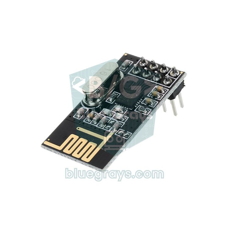
What is the nRF24L01 and how does it work?
The nRF24L01 is a 2.4 GHz radio transceiver chip made by Nordic Semiconductor; almost every module sold today carries the improved nRF24L01+ version or a compatible clone chip. The module talks to the Arduino over SPI: the Arduino writes the settings and the data to send over SPI, and the chip takes care of the rest. Nordic's hardware protocol, called Enhanced ShockBurst, wraps every packet with an address and a CRC (error check). When the receiver gets a packet correctly, it automatically sends an acknowledgement (ACK) back to the transmitter; if no ACK arrives, the transmitter retries on its own. So your code just says "send", and the retries and error checking happen in hardware.
A packet carries at most 32 bytes of data. That may sound small, but two joystick axes, a few buttons and several sensor values fit easily. The module uses one of 126 channels, and the channel frequency is 2400 + channel number (MHz); channel 76, for example, is 2476 MHz. A receiver can listen to 6 different addresses (called pipes) at the same time, so one hub can collect data from six transmitters.
| Feature | Value |
|---|---|
| Frequency | 2.400–2.525 GHz (126 channels, 1 MHz spacing) |
| Data rate | 250 kbps, 1 Mbps, 2 Mbps |
| Supply voltage | 1.9–3.6 V (3.3 V in practice) |
| Input pins | 5 V tolerant (CE, CSN, SCK, MOSI) |
| Output power | 0, −6, −12, −18 dBm |
| Current (transmitting, 0 dBm) | About 11.3 mA |
| Current (receiving, 2 Mbps) | About 13.5 mA |
| Power down | About 900 nA |
| Receiver sensitivity | −94 dBm (250 kbps), −85 dBm (1 Mbps), −82 dBm (2 Mbps) |
| Payload size | 1–32 bytes |
| Interface | SPI, up to 10 MHz |
| Number of pipes | 6 |
nRF24L01 vs nRF24L01+PA+LNA
You'll find two types of module on the market. On the standard module the antenna is a zigzag copper trace printed on the board. The nRF24L01+PA+LNA version adds an RF front-end chip in front of the same transceiver: the PA (Power Amplifier) boosts the outgoing signal, and the LNA (Low Noise Amplifier) amplifies weak incoming signals before they reach the chip. A screw-on external antenna attaches to an SMA connector. Both modules have the same pinout and use the same code, and they talk to each other without any problem; the difference is range and current draw. The figures below are approximate and depend on the environment.
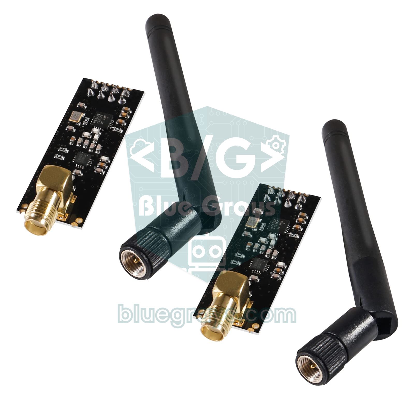
| Feature | nRF24L01+ (PCB antenna) | nRF24L01+PA+LNA |
|---|---|---|
| Antenna | Printed on the board | External SMA antenna |
| Output power | Up to 0 dBm (1 mW) | Up to +20 dBm (100 mW), depending on the model |
| Peak current when transmitting | About 12 mA | Up to 115 mA |
| Peak current when receiving | About 13.5 mA | Up to 45 mA |
| Open-air range (250 kbps) | 50–100 m | 800–1100 m |
| Indoor range | 10–30 m, 1–2 walls | Several floors and tens of metres |
| Recommended supply | 3.3 V pin + 10 µF capacitor | Separate 3.3 V regulator + capacitor |
nRF24L01 pinout and Arduino wiring
The module has 8 pins arranged in a 2×4 header. The pin with the square solder pad is pin 1, which is GND; VCC sits right next to it. CE (Chip Enable) switches the module into listening or transmitting mode, and CSN (Chip Select Not) is pulled LOW to say "I'm talking to you now" on the SPI bus. SCK, MOSI and MISO are the standard SPI lines and must go to your board's fixed SPI pins, while CE and CSN can go to any digital pins. The IRQ pin is optional; it goes LOW when a packet arrives or a transmission finishes and is used if you want to work with interrupts. For how SPI works, see What is SPI, and for your board's full pin map, use the Pinout tool.
| nRF24L01 pin | Function | Arduino Uno / Nano | Arduino Mega | ESP32 | Raspberry Pi Pico |
|---|---|---|---|---|---|
| 1 GND | Ground | GND | GND | GND | GND |
| 2 VCC | Supply (3.3 V) | 3.3V | 3.3V | 3V3 | 3V3(OUT) |
| 3 CE | Mode select | D9 | D9 | GPIO 4 | GP6 |
| 4 CSN | SPI chip select | D10 | D10 | GPIO 5 | GP5 |
| 5 SCK | SPI clock | D13 | D52 | GPIO 18 | GP2 |
| 6 MOSI | Data from board to module | D11 | D51 | GPIO 23 | GP3 |
| 7 MISO | Data from module to board | D12 | D50 | GPIO 19 | GP4 |
| 8 IRQ | Interrupt (optional) | Not connected | Not connected | Not connected | Not connected |
The most common mistake: power supply and the 10 µF capacitor
Most nRF24L01 problems are caused not by code but by power. The module draws short, sharp current pulses at the moment it transmits. Long jumper wires and a weak 3.3 V source can't keep up with these pulses; the voltage dips for an instant, and the chip sends a corrupted packet, misses ACKs or resets itself. According to the official documentation, the Arduino Uno's 3.3 V pin supplies at most 50 mA; that's enough for the standard module but not for the PA+LNA version, which draws up to 115 mA. On some Nano clones the 3.3 V pin comes from the USB-serial chip and is even weaker. The symptoms will sound familiar: write() sometimes succeeds and sometimes doesn't, the module works better when you touch it, or the range stops at a few metres.
- 10 µF capacitor: Fit a 10 µF electrolytic capacitor across the module's VCC and GND pins, as close to them as possible. The long leg (+) goes to VCC and the striped side (−) to GND. Anything from 10 to 100 µF also works; you can read why it helps in What is a capacitor.
- 100 nF ceramic capacitor: A small ceramic capacitor (marked 104) in parallel with the electrolytic filters out high-frequency noise. You can decode capacitor markings with the Capacitor code tool.
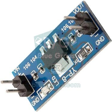
- Socket adapter: The 8-pin adapter boards sold for the nRF24L01 come with an AMS1117-3.3 regulator and capacitors already fitted. You feed 5 V into the adapter's VCC, and the module gets a clean 3.3 V.
- Separate regulator: Power the PA+LNA version not from the Arduino's 3.3 V pin but from a separate AMS1117-3.3 regulator fed from 5 V, and connect all the grounds together.
- Short wires: Keep jumper wires under 10 cm if you can; long, loose wires disturb both the supply and the SPI signals.
Installing the RF24 library
- In the Arduino IDE, open Tools > Manage Libraries or click the library icon on the left.
- Type RF24 in the search box and install the RF24 library by TMRh20. RF24Network, RF24Mesh and RF24Ethernet are separate libraries and aren't needed to get started.
- After installation you'll find the GettingStarted example under File > Examples > RF24. The code in this article follows the syntax of RF24 version 1.5 and later.
- If this is your first time installing a library, follow the steps in How to add a library in Arduino.
Address, channel and data rate: getting two modules to agree
For two modules to hear each other, some settings must be exactly the same on both sides. Think of it like a walkie-talkie conversation: if you're not tuned to the same frequency (channel), the same speaking speed (data rate) and the same call sign (address), you won't hear the other side. The address is a 5-byte array, and the easiest way to write it in code is as a 5-character string such as "00001". Think of the address not as a device's identity but as a shared path between two devices: the transmitter drops packets on that path, and the receiver listening to that path picks them up. Payload size matters too; RF24 uses fixed-size payloads by default, and if the receiver doesn't expect the same size as the transmitter, it never sees the packet.
| Setting | RF24 function | Value in this article | Note |
|---|---|---|---|
| Channel | setChannel(76) | 76 (2476 MHz) | 0–125; must match on both sides |
| Data rate | setDataRate(RF24_250KBPS) | 250 kbps | Lower speed means longer range |
| Address | stopListening(address) / openReadingPipe(1, address) | "00001" | Transmitter's target = receiver's pipe |
| Payload size | setPayloadSize(sizeof(data)) | 32 bytes (5 in the joystick example) | With fixed size, both sides must match |
| Output power | setPALevel(RF24_PA_LOW) | Low | Doesn't have to match; sets the range |
| Auto-ACK and CRC | On by default | 16-bit CRC | If you turn them off, do it on both sides |
Transmitter code (TX)
For your first test, connect the two Arduinos to two separate USB ports and put 1–2 metres between the modules. Upload the transmitter code below to one of them. Every second it sends a numbered message and prints to the Serial Monitor whether the receiver acknowledged it. Don't forget to set the Serial Monitor to 115200 baud.
1#include <SPI.h>
2#include <RF24.h>
3
4RF24 radio(9, 10);                        // CE, CSN pinleri / CE, CSN pins
5const uint8_t address[6] = "00001";       // iki tarafta aynı adres / same address on both sides
6char message[32];                         // en fazla 32 bayt / 32 bytes max
7uint16_t counter = 0;
8
9void setup() {
10  Serial.begin(115200);
11  if (!radio.begin()) {                   // modül cevap vermiyor / module not responding
12    Serial.println(F("nRF24L01 bulunamadi, kablolari kontrol et!"));
13    while (true) {}
14  }
15  radio.setChannel(76);                   // kanal 76 = 2476 MHz / channel 76 = 2476 MHz
16  radio.setDataRate(RF24_250KBPS);        // en uzun menzil / longest range
17  radio.setPALevel(RF24_PA_LOW);          // masa testi için düşük güç / low power for desk tests
18  radio.setPayloadSize(sizeof(message));  // paket boyu 32 bayt / 32-byte payload
19  radio.stopListening(address);           // verici modu + hedef adres / TX mode + target address
20}
21
22void loop() {
23  snprintf(message, sizeof(message), "Merhaba BlueGrays #%u", counter++);
24  bool ok = radio.write(message, sizeof(message));   // onay (ACK) geldi mi? / was it acknowledged?
25  if (ok) {
26    Serial.print(F("Gonderildi: "));
27    Serial.println(message);
28  } else {
29    Serial.println(F("Onay gelmedi"));
30  }
31  delay(1000);
32}
Receiver code (RX)
1#include <SPI.h>
2#include <RF24.h>
3
4RF24 radio(9, 10);                        // CE, CSN pinleri / CE, CSN pins
5const uint8_t address[6] = "00001";       // vericiyle aynı adres / same address as the transmitter
6char message[32];
7
8void setup() {
9  Serial.begin(115200);
10  if (!radio.begin()) {
11    Serial.println(F("nRF24L01 bulunamadi, kablolari kontrol et!"));
12    while (true) {}
13  }
14  radio.setChannel(76);                   // ayarlar vericiyle aynı / settings match the transmitter
15  radio.setDataRate(RF24_250KBPS);
16  radio.setPALevel(RF24_PA_LOW);
17  radio.setPayloadSize(sizeof(message));
18  radio.openReadingPipe(1, address);      // 1 numaralı boruyu aç / open pipe 1
19  radio.startListening();                 // alıcı modu / RX mode
20}
21
22void loop() {
23  if (radio.available()) {                // paket geldi mi? / has a packet arrived?
24    radio.read(message, sizeof(message));
25    Serial.print(F("Gelen: "));
26    Serial.println(message);
27  }
28}
radio.write() sends the packet and returns true if the receiver acknowledges it; with the default settings it retries 15 times about 1.5 ms apart before returning false. On the receiver, openReadingPipe(1, address) sets pipe 1 to the transmitter's address, startListening() switches the module into listening mode, available() tells you whether a packet is waiting and read() copies it into your variable. If the receiver's Serial Monitor shows lines counting up like "Gelen: Merhaba BlueGrays #0", "#1", "#2", your link is working.
Range: from 100 metres to 1 kilometre
Three things determine range: output power, receiver sensitivity and the environment. The lower the data rate, the weaker the signals the receiver can decode; sensitivity is −94 dBm at 250 kbps but −82 dBm at 2 Mbps. That 12 dB difference means roughly 4 times the range in open space. Walls, trees, human bodies and metal surfaces weaken 2.4 GHz signals considerably, and Wi-Fi routers, Bluetooth devices and microwave ovens share the same band.
| Data rate | Receiver sensitivity | Relative range | When to use it |
|---|---|---|---|
| 250 kbps | −94 dBm | Longest | Remotes, distant sensors |
| 1 Mbps | −85 dBm | Medium | General use (RF24 default) |
| 2 Mbps | −82 dBm | Shortest | High speed, short distance |
Channel choice matters too. The commonly used Wi-Fi channels 1, 6 and 11 cover roughly 2401–2473 MHz; nRF24L01 channels 74–83 sit above that and are quieter as long as no nearby router uses Wi-Fi channel 12 or 13. In Europe (and in Turkey) the licence-free 2.4 GHz band runs from 2400 to 2483.5 MHz, so don't use channels above 83; the channels of 100 and above that some online examples suggest are outside this band, and the exact limits depend on your country's rules. To get more range, try the following:
- Use 250 kbps: Remotes and sensor data don't need high speed, and the lower rate gives you range.
- Fix the power supply first, then raise the power: RF24_PA_MAX only makes sense with a stable 3.3 V and a capacitor; raising the power on a weak supply makes things worse.
- Mount the antennas high and in the same orientation: 1–2 metres above the ground with both antennas standing upright the same way noticeably improves range.
- Keep it away from metal: Don't put the module inside a metal box or right next to a big battery pack.
- Wrap an unshielded PA+LNA board: Wrapping a PA+LNA module without a metal can in electrical tape and then aluminium foil reduces the interference it causes to itself; the foil must not touch any pin or the antenna connector.
- Don't transmit without an antenna: Running a PA+LNA module at full power with no antenna attached stresses the power amplifier.
Wireless remote control with a joystick
Now let's build a real project: use a joystick on one Arduino to control a servo motor and an LED on a second Arduino wirelessly. On the transmitter, the joystick's VRx pin goes to A0, VRy to A1 and the button (SW) to D2; you'll find the details in Joystick module. On the receiver, the servo's signal wire goes to D3 and the LED goes to D4 through a 220 Ω resistor. The nRF24L01 wiring on both sides is the same as in the table above.
The cleanest way to send several values in one packet is a struct. There's an important detail here: you should use fixed-size types such as int16_t and uint8_t. An int is 2 bytes on the Arduino Uno but 4 bytes on the ESP32, and the ESP32 compiler also adds padding bytes at the end of the struct for alignment. If the same struct is 5 bytes on the Uno and 6 bytes on the ESP32, the payload sizes don't match and no data arrives at all. __attribute__((packed)) removes that padding and makes the struct 5 bytes on every board. First, the transmitter:
1#include <SPI.h>
2#include <RF24.h>
3
4struct __attribute__((packed)) JoystickData {   // her kartta 5 bayt / 5 bytes on every board
5  int16_t x;
6  int16_t y;
7  uint8_t button;
8};
9
10RF24 radio(9, 10);                        // CE, CSN pinleri / CE, CSN pins
11const uint8_t address[6] = "JOY01";       // kumanda adresi / remote address
12JoystickData data;
13
14void setup() {
15  pinMode(2, INPUT_PULLUP);               // joystick butonu (SW) / joystick button (SW)
16  if (!radio.begin()) {
17    while (true) {}                       // modül yok / no module
18  }
19  radio.setChannel(76);
20  radio.setDataRate(RF24_250KBPS);
21  radio.setPALevel(RF24_PA_HIGH);         // orta-yüksek güç / medium-high power
22  radio.setPayloadSize(sizeof(data));
23  radio.stopListening(address);           // verici modu / TX mode
24}
25
26void loop() {
27  data.x = analogRead(A0);                // VRx ekseni 0-1023 / VRx axis 0-1023
28  data.y = analogRead(A1);                // VRy ekseni 0-1023 / VRy axis 0-1023
29  data.button = (digitalRead(2) == LOW);  // basılıysa 1 / 1 when pressed
30  radio.write(&data, sizeof(data));
31  delay(50);                              // saniyede 20 paket / 20 packets per second
32}
Then the receiver that drives the servo and the LED:
1#include <SPI.h>
2#include <RF24.h>
3#include <Servo.h>
4
5struct __attribute__((packed)) JoystickData {   // vericiyle birebir aynı / identical to the transmitter
6  int16_t x;
7  int16_t y;
8  uint8_t button;
9};
10
11RF24 radio(9, 10);                        // CE, CSN pinleri / CE, CSN pins
12const uint8_t address[6] = "JOY01";       // vericiyle aynı / same as the transmitter
13JoystickData data;
14Servo servo;
15unsigned long lastPacket = 0;
16
17void setup() {
18  pinMode(4, OUTPUT);                     // LED çıkışı / LED output
19  servo.attach(3);                        // servo sinyal pini / servo signal pin
20  if (!radio.begin()) {
21    while (true) {}
22  }
23  radio.setChannel(76);
24  radio.setDataRate(RF24_250KBPS);
25  radio.setPALevel(RF24_PA_HIGH);
26  radio.setPayloadSize(sizeof(data));
27  radio.openReadingPipe(1, address);
28  radio.startListening();                 // alıcı modu / RX mode
29}
30
31void loop() {
32  if (radio.available()) {
33    radio.read(&data, sizeof(data));
34    servo.write(map(data.x, 0, 1023, 0, 180));   // X ekseni -> servo açısı / X axis -> servo angle
35    digitalWrite(4, data.button ? HIGH : LOW);   // buton LED'i yakar / button lights the LED
36    lastPacket = millis();
37  }
38  if (millis() - lastPacket > 500) {      // 0,5 sn paket yok: güvenli konum / no packet for 0.5 s: failsafe
39    servo.write(90);
40    digitalWrite(4, LOW);
41  }
42}
The transmitter sends 20 packets per second; for each packet the receiver maps the X axis to 0–180 degrees and writes it to the servo. The failsafe part on the receiver is very important: if the remote's battery dies or you go out of range, the last command isn't applied forever; when no packet arrives for 0.5 seconds the servo centres and the LED turns off. If you're building a robot car, stop the motors in the same place. Powering the servo from a separate 5 V source instead of the Arduino's 5 V pin also keeps the servo's current spikes from disturbing the nRF24L01. Connect the Y axis to an L298N motor driver and you have a wireless robot car; for servo details, see What is a servo motor.
Two-way communication and multiple transmitters
The nRF24L01 can't transmit and listen at the same time, but there's an easy way to get two-way communication: an ACK payload, meaning data sent inside the acknowledgement packet. The receiver prepares the data to attach to the next ACK in advance with writeAckPayload() (a battery voltage or sensor reading, for example), and after a successful write() the transmitter reads that reply with available() and read(). For this, both sides must call enableDynamicPayloads() and enableAckPayload(). For multiple transmitters, the receiver has 6 pipes: pipes 0 and 1 take a full 5-byte address, while pipes 2–5 share the rest of pipe 1's address and differ in a single byte only. In RF24 that byte is the first character of the address array, which is why addresses such as "1Node", "2Node" and "3Node" differ only in their first character. For larger networks there are the RF24Network and RF24Mesh libraries.
Connecting the nRF24L01 to an ESP32
The RF24 library works on the ESP32 unchanged, and radio.begin() uses the default VSPI bus: SCK = GPIO 18, MISO = GPIO 19, MOSI = GPIO 23. GPIO 5 is a good choice for CSN and GPIO 4 for CE. The 3.3 V regulator on ESP32 DevKit boards is stronger than the Uno's, but don't skip the 10 µF capacitor. On models such as the ESP32-C3 or ESP32-S3 the default SPI pins are different, so check your board's pin map. Because the ESP32's Wi-Fi also runs at 2.4 GHz, pick an nRF24L01 channel well away from your router's Wi-Fi channel if you use both together. The code below reads the joystick transmitter's packets on an ESP32; with the same structure you can use the ESP32 as a gateway that forwards data from nRF24L01 nodes to the internet. If you're new to the board, start with What is the ESP32.
1#include <SPI.h>
2#include <RF24.h>
3
4struct __attribute__((packed)) JoystickData {   // packed olmasa 6 bayt olurdu / 6 bytes without packed
5  int16_t x;
6  int16_t y;
7  uint8_t button;
8};
9
10RF24 radio(4, 5);                         // CE = GPIO 4, CSN = GPIO 5 pinleri / CE = GPIO 4, CSN = GPIO 5 pins
11const uint8_t address[6] = "JOY01";
12JoystickData data;
13
14void setup() {
15  Serial.begin(115200);
16  if (!radio.begin()) {                   // varsayılan VSPI: SCK 18, MISO 19, MOSI 23 / default VSPI pins
17    Serial.println("nRF24L01 bulunamadi!");
18    while (true) delay(1000);
19  }
20  radio.setChannel(76);
21  radio.setDataRate(RF24_250KBPS);
22  radio.setPALevel(RF24_PA_HIGH);
23  radio.setPayloadSize(sizeof(data));     // packed sayesinde 5 bayt / 5 bytes thanks to packed
24  radio.openReadingPipe(1, address);
25  radio.startListening();
26}
27
28void loop() {
29  if (radio.available()) {
30    radio.read(&data, sizeof(data));
31    Serial.printf("X=%d  Y=%d  Buton=%d\n", data.x, data.y, data.button);
32  }
33}
If you only need to link ESP32 boards together, ESP-NOW, which needs no extra module, is also a good option; the nRF24L01's advantage is that it also works with cheap, low-power boards such as the Uno, Nano and Pro Mini.
nRF24L01 with the Raspberry Pi Pico and MicroPython
For MicroPython on the Pico, you use the nrf24l01.py driver from the official micropython-lib repository. You can copy the file to the Pico with Thonny or install it from your computer with mpremote mip install nrf24l01. The wiring uses SPI0: SCK = GP2, MOSI = GP3, MISO = GP4, CSN = GP5, CE = GP6 and VCC = 3V3(OUT). The driver's defaults differ from RF24's (channel 46, 16-byte payload), so to talk to the Arduino we set the channel, data rate and payload size explicitly in the code. The code below decodes the joystick transmitter's packets on the Pico:
1from machine import Pin, SPI
2import struct
3import utime
4from nrf24l01 import NRF24L01, POWER_2, SPEED_250K
5
6spi = SPI(0, sck=Pin(2), mosi=Pin(3), miso=Pin(4))   # SPI0 pinleri / SPI0 pins
7csn = Pin(5, mode=Pin.OUT, value=1)                  # CSN pini GP5 / CSN pin GP5
8ce = Pin(6, mode=Pin.OUT, value=0)                   # CE pini GP6 / CE pin GP6
9
10nrf = NRF24L01(spi, csn, ce, channel=76, payload_size=5)   # Arduino ile aynı / same as the Arduino
11nrf.set_power_speed(POWER_2, SPEED_250K)             # -6 dBm güç, 250 kbps / -6 dBm power, 250 kbps
12nrf.open_rx_pipe(1, b"JOY01")                        # vericinin adresi / transmitter address
13nrf.start_listening()                                # alıcı modu / RX mode
14print("Dinleniyor... / Listening...")
15
16while True:
17    if nrf.any():                                    # paket geldi mi? / packet waiting?
18        x, y, button = struct.unpack("<hhB", nrf.recv())   # 2 + 2 + 1 bayt / 2 + 2 + 1 bytes
19        print("X:", x, "Y:", y, "Buton:", button)
20    utime.sleep_ms(5)
struct.unpack("<hhB") turns the 5 incoming bytes into two signed 16-bit numbers and one byte; the leading "<" sets little-endian byte order, which is what the AVR and ESP32 use. If the module isn't found, the driver raises "nRF24L01+ Hardware not responding", the MicroPython equivalent of begin() returning false on the Arduino. If you're new to the Pico, read What is the Raspberry Pi Pico first.
radio.begin() returns false: step-by-step fix
If the Serial Monitor shows "nRF24L01 bulunamadi" or the "radio hardware is not responding!!" message from the RF24 examples, the Arduino can't talk to the module over SPI at all. In that case the problem is almost always the wiring or the power supply, not the code. First upload the diagnostic sketch below; it prints all the module's settings in a readable form.
1#include <SPI.h>
2#include <RF24.h>
3#include "printf.h"                       // RF24 ile gelir / ships with RF24
4
5RF24 radio(9, 10);                        // kendi CE, CSN pinlerin / your CE, CSN pins
6
7void setup() {
8  Serial.begin(115200);
9  printf_begin();                         // printPrettyDetails için / needed for printPrettyDetails
10  bool ok = radio.begin();
11  Serial.print(F("begin(): "));
12  Serial.println(ok ? "true" : "false");
13  Serial.print(F("isChipConnected(): "));
14  Serial.println(radio.isChipConnected() ? "true" : "false");
15  radio.printPrettyDetails();             // tüm ayarları yazdır / print every setting
16}
17
18void loop() {
19}- Check MOSI and MISO: These are the two wires that get swapped most often. On the Uno and Nano, MOSI = D11, MISO = D12 and SCK = D13; on the Mega they're 51, 50 and 52.
- Do CE and CSN match the code: If you wrote RF24 radio(9, 10), CE goes to D9 and CSN to D10. RF24's GettingStarted example uses pins 7 and 8; if you're trying the example unchanged, wire it that way.
- Is the supply 3.3 V: Measure between VCC and GND with a multimeter; you should see 3.0–3.6 V. If the module was ever connected to 5 V, it may be damaged.
- Look at the printPrettyDetails output: If the addresses and register values all show 0x00 or 0xff, the SPI bus isn't working. If the values look sensible but there's still no link, the problem is the CE pin, the settings or the power supply.
- Shorten the wires and lower the SPI speed: With long or loose wires, write RF24 radio(9, 10, 4000000) to drop the SPI speed from the default 10 MHz to 4 MHz.
- Swap the module: If everything else checks out, try a spare module; cheap multipacks can contain a faulty one.
No data or patchy data: common problems
| Symptom | Likely cause | Fix |
|---|---|---|
| begin() is true but nothing reaches the receiver | Channel, data rate, address or payload size differ between the two sides | Compare the four settings side by side in both sketches |
| No data from the Uno to the ESP32 | Different struct size (5 vs 6 bytes) | Use fixed-size types and __attribute__((packed)) |
| write() is false but the receiver gets the data | The receiver's ACK isn't reaching the transmitter, usually due to the receiver's power supply | Add a 10 µF capacitor to the receiver module too |
| Constant empty or garbage data on screen | Loose SPI wire or a broken MISO connection | Replace the wires and lower the SPI speed to 4 MHz |
| Doesn't work side by side, works when moved apart | The receiver is overloaded at full power | Use setPALevel(RF24_PA_LOW) or RF24_PA_MIN |
| Works better when you touch it | Unstable supply or an unshielded PA+LNA | Capacitor, separate regulator and foil shielding |
| The link drops after a few metres | 2 Mbps data rate, weak supply or Wi-Fi interference | 250 kbps, clean supply, a channel between 74 and 83 |
nRF24L01 project ideas
- Wireless robot car remote: Drive a robot car from tens of metres away with a two-joystick remote.
- Garden sensor station: Send soil moisture sensor and temperature data from a battery-powered transmitter to a display in the house. With radio.powerDown() the module draws about 900 nA while asleep; you can estimate battery life with the Battery life tool.
- Wireless door and motion alarm: Sound a buzzer at the hub when a PIR sensor or a reed switch is triggered.
- Multi-room temperature network: Collect readings from sensors in six rooms on a single receiver over six pipes.
- ESP32 gateway: Forward data from nRF24L01 nodes to the internet, your phone or a dashboard with an ESP32.
- Wireless scoreboard: Update a 7-segment scoreboard in a sports hall from button remotes.
Despite its low price, the nRF24L01 offers longer range, lower latency and multi-device support compared with Bluetooth; all it asks for is a clean 3.3 V supply and matching settings on both sides. If you want phone control, the HC-05 Bluetooth module may suit you better, and for kilometres of range, LoRa; you'll find a comparison of the options in Arduino wireless communication modules. In the BlueGrays app you'll find projects such as communication between two Arduinos, joystick control of a servo and an LED, and a remote-controlled car, step by step with circuit diagrams and ready-to-use code.
Frequently asked questions
What is the range of the nRF24L01?
The standard nRF24L01+ with a PCB antenna reaches about 50–100 metres in open space at 250 kbps, and 10–30 metres indoors depending on the walls. The nRF24L01+PA+LNA version with an external antenna can reach 800–1100 metres in open, unobstructed space. Reaching these figures takes a clean 3.3 V supply, a 10 µF capacitor and a low data rate.
Can the nRF24L01 run on 5V?
No. The VCC pin works between 1.9 and 3.6 V, and 5 V can destroy the chip. The CE, CSN, SCK and MOSI input pins, however, are 5 V tolerant, so they can be connected to an Arduino Uno's SPI pins without a level shifter. If you want to power the module from 5 V, use a socket adapter with an AMS1117-3.3 regulator.
Why do I get the "radio hardware is not responding" error?
This message is printed when radio.begin() returns false, and it means the Arduino can't talk to the module over SPI. The most common causes are swapped MOSI and MISO, CE and CSN pins that differ from the code, a weak or 5 V supply and loose jumper wires. Check the wiring and look at the printPrettyDetails() output to narrow the problem down.
nRF24L01 or HC-05 Bluetooth: which should I use?
If you need long range, low latency and several devices between Arduinos, the nRF24L01 is the better choice. If you want to control things from a phone, choose a Bluetooth module like the HC-05 or an ESP32, because phones don't speak the nRF24L01's protocol. The HC-05 typically reaches around 10 metres, while the nRF24L01 goes much further for a similar price.
How many transmitters can one nRF24L01 receiver listen to?
A receiver can listen to 6 pipes at once, so it can collect data directly from 6 transmitters. Pipes 2–5 share the body of pipe 1's address and differ in a single byte only. For more nodes, you can poll the transmitters in turn or build much larger networks with the RF24Network and RF24Mesh libraries.
Can the nRF24L01 connect to a phone?
Not directly. Although the nRF24L01 works in the same 2.4 GHz band, it doesn't use the Wi-Fi or Bluetooth protocols. If you want phone control, put an ESP32 at the centre of your nRF24L01 network and pass the data to the phone over Wi-Fi or Bluetooth. That way the remote nodes talk nRF24L01 and the phone talks to the ESP32.
Projects to build after reading this
See all projects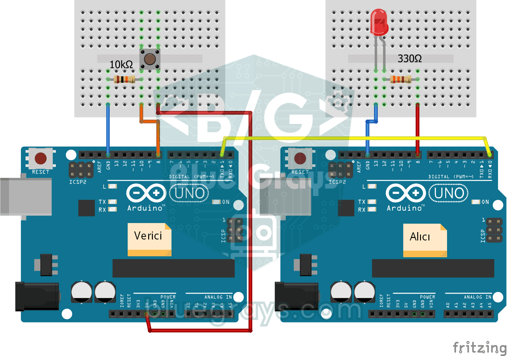
One-Way Communication Between 2 Arduinos
You get two Arduinos talking over a single wire: press the button on one and the LED on the other lights up, press it again and it goes off. The sending board reports the button press with a short mes
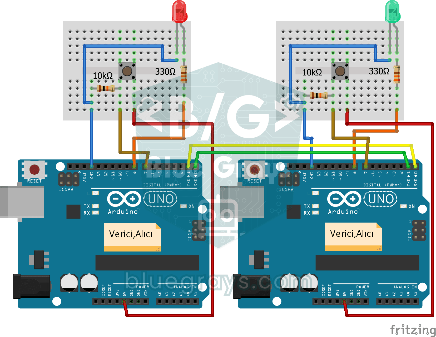
Two-Way Communication Between 2 Arduinos
Two Arduinos are wired together and talk to each other: press the button on one and the light on the other comes on, press it again and it goes off. Both boards run the same program, so each one both
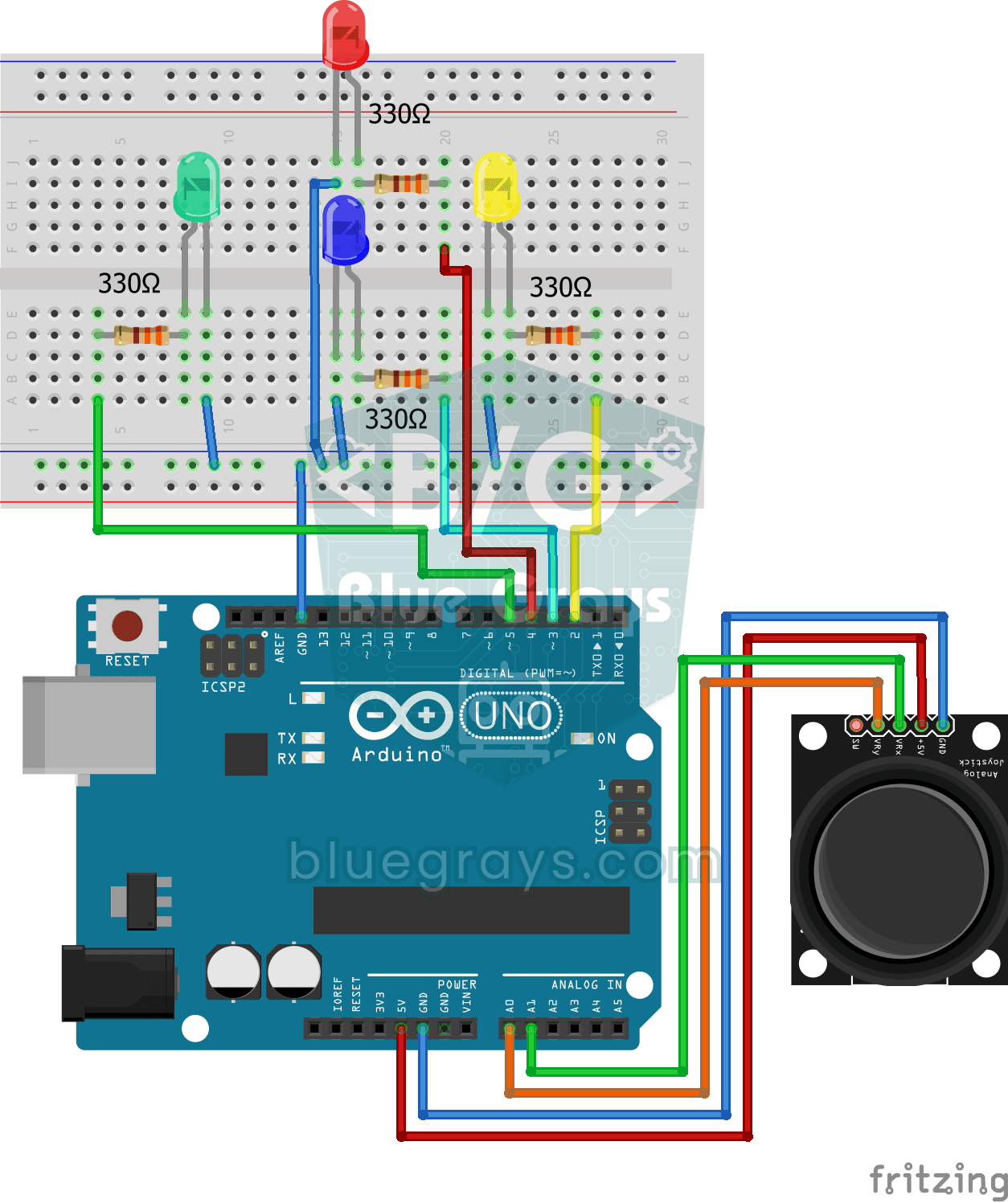
Led Control with Joystick
Push the little stick on the joystick all the way in any direction and the LED for that direction lights up: there are four different colours for right, left, up and down. Let go of the stick, it spri
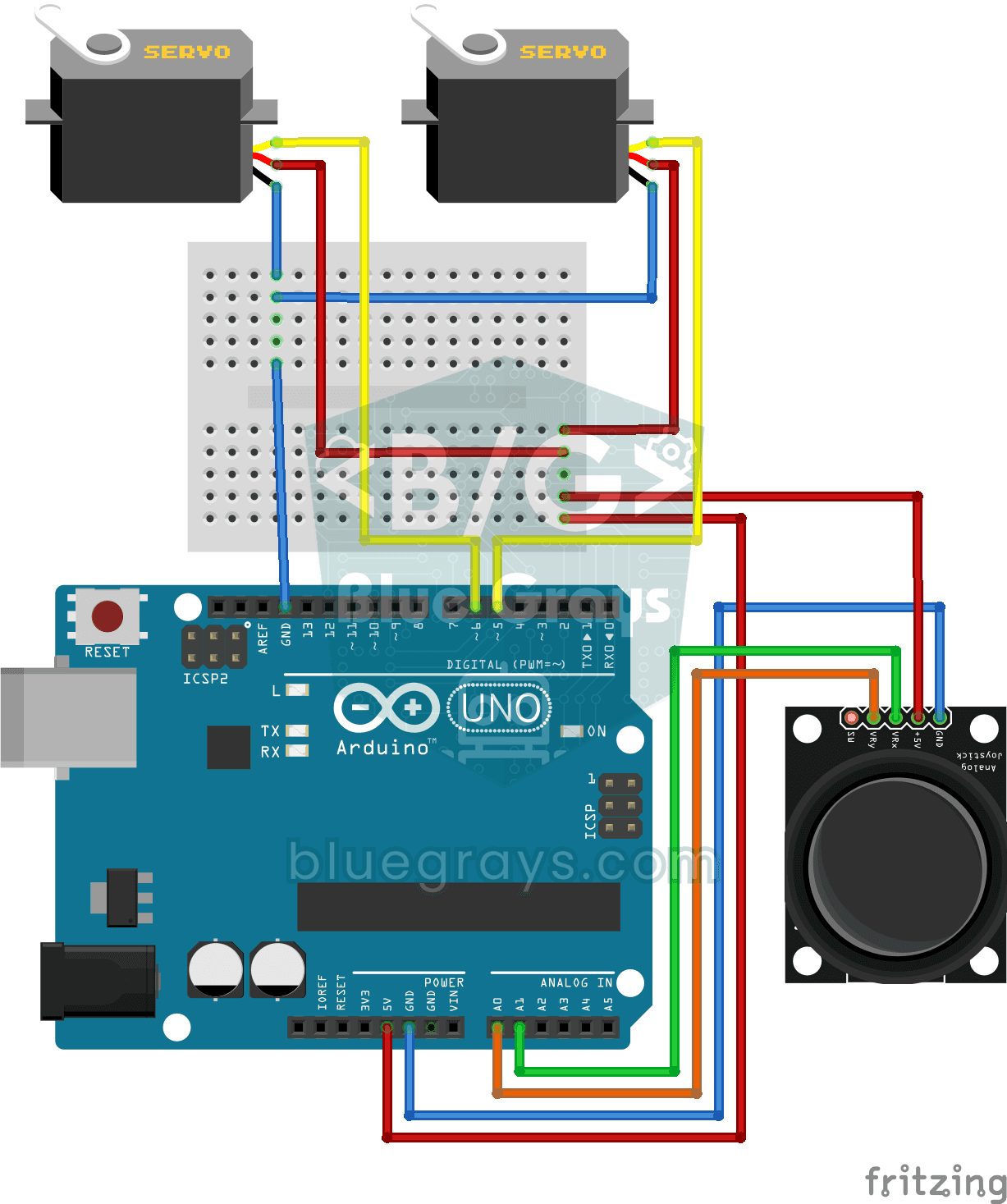
Servo Control with Joystick
Steer two motors with a joystick, just like turning a security camera. Push the stick left or right and the bottom servo motor slowly turns, push it up or down and the top servo tilts up and down; let

Bluetooth Controlled Car with L298N
Turn your phone into a remote and drive your own robot car. The Arduino receives commands from a remote-control app on your phone through a Bluetooth module and spins the wheels with a motor driver; t
Control an LED from Your Phone via Bluetooth
A small rehearsal for switching the lights in your room on and off from your phone. The Bluetooth module passes the letters sent from your phone to the Arduino; one letter turns on the red LED, anothe
Led On/Off with IR Receiver and Remote Control
Like controlling three separate lamps without leaving your armchair: keys 1, 2 and 3 on the remote turn on the blue, red and green LEDs, and keys 4, 5 and 6 turn them off in the same order. The power

ESP32 IR Universal Remote (IR Receiver + Remote Control + 3 LEDs + Buzzer + OLED)
With the ESP32, you can read a standard IR remote control and use it to control your own device! In this project, we use an infrared receiver (NEC protocol, 38 kHz) to capture the signals from a 20-button IR remote. We’ve defined different actions for each button: buttons 1, 2, and 3 toggle three separate LEDs; the PWR button turns them all off; and the numbers 4–9 display special characters on the OLED. The SSD1306 OLED display shows the last button pressed in large font, along with a descripti