
What Is UART? TX/RX Wiring, Baud Rate and Arduino Serial Guide
What is UART and how does it work? TX/RX crossover, baud rate, start/stop bits, linking two Arduinos, SoftwareSerial, 5V/3.3V levels, ESP32 Serial2, Pico UART.
The short answer to what is UART: UART (Universal Asynchronous Receiver-Transmitter) is the serial communication hardware that lets two devices exchange data byte by byte over just two data wires (TX and RX) plus a common GND. Every line you see in the Serial Monitor when your Arduino is plugged into the computer arrives over UART. Dozens of modules, such as GPS receivers, the HC-05 Bluetooth module, the ESP-01 Wi-Fi module, the SIM800L GSM module, fingerprint readers and MP3 players, also talk to the Arduino over UART.
In this post we explain step by step why UART needs no clock line, what baud rate is, how a byte is framed with start, data and stop bits, why TX and RX are crossed, how to make two Arduinos talk first one way and then both ways, the limits of SoftwareSerial, how to connect 5 V and 3.3 V boards safely, the ESP32's three UARTs and the Raspberry Pi Pico's UART pins. In the last section you'll see how to build packets with start and end characters so data never gets mixed up, and the most common mistakes.
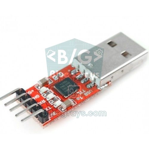
What is UART and how does it work?
The word "asynchronous" in UART's name is the key: in I2C and SPI a clock signal is sent along with the data, whereas UART has no clock line. Instead, both sides agree on a speed in advance, called the baud rate. When idle, the line sits HIGH (1). To send a byte, the transmitter pulls the line LOW for one bit time; this is the start bit, telling the receiver "start counting now". The 8 data bits follow, least significant bit (LSB) first, an optional parity bit may come next, and finally the line is held HIGH for at least one bit time; this is the stop bit. The Arduino's default setting is 8N1: 8 data bits, no parity, 1 stop bit.
| Bit | Start | D0 | D1 | D2 | D3 | D4 | D5 | D6 | D7 | Stop |
|---|---|---|---|---|---|---|---|---|---|---|
| Letter 'A' (0x41 = 0100 0001) | 0 | 1 | 0 | 0 | 0 | 0 | 0 | 1 | 0 | 1 |
| Line level | LOW | HIGH | LOW | LOW | LOW | LOW | LOW | HIGH | LOW | HIGH |
Each bit lasts 1 / baud seconds. At 9600 baud a bit takes 104.2 microseconds; since an 8N1 frame is 10 bits per byte (start + 8 data + stop), at most 960 bytes per second can be sent. After catching the falling edge of the start bit, the receiver samples the line in the middle of each bit. Even if the two clocks differ slightly, data is read correctly as long as the error accumulated over 10 bits stays under half a bit; that's why the total baud error must stay below roughly 2–3%. With its 16 MHz crystal the Arduino Uno can't produce 115200 baud exactly, and the real rate is about 2.1% off; it still works because it's within the limit.
| Baud | Bit time | Max bytes per second (8N1) | Where it's used |
|---|---|---|---|
| 9600 | 104.2 µs | 960 | NEO-6M GPS, HC-05 data mode, DFPlayer Mini, the classic Serial Monitor setting |
| 19200 | 52.1 µs | 1920 | Some sensors and older modems |
| 38400 | 26.0 µs | 3840 | HC-05 AT command mode |
| 57600 | 17.4 µs | 5760 | Older Arduino bootloaders, upper limit for SoftwareSerial |
| 115200 | 8.68 µs | 11520 | ESP32 and ESP-01, fast debug output |
| 1000000 and above | 1 µs or less | 100,000+ | Short board-to-board links, fast data logging |
UART vs I2C vs SPI
The three most common serial communication methods on the Arduino are UART, I2C and SPI. UART works one-to-one between two devices only, and both sides can talk whenever they like (full duplex). I2C gathers dozens of devices on the same two wires using addresses; SPI is much faster with four wires but needs a separate select pin for each device. For details, see the What is I2C and What is SPI posts.
| Feature | UART | I2C | SPI |
|---|---|---|---|
| Wires | 2 (TX, RX) + GND | 2 (SDA, SCL) + GND | 4 (SCK, MOSI, MISO, CS) + GND |
| Clock line | None (asynchronous) | Yes | Yes |
| Number of devices | 2 (point-to-point) | Up to 127, by address | As many as CS pins |
| Typical speed | 9600–115200 baud | 100–400 kHz | 1–80 MHz |
| Both directions at once | Yes (full duplex) | No | Yes |
| Typical modules | GPS, Bluetooth, GSM, ESP-01, fingerprint | OLED, LCD, RTC, BME280 | SD card, RFID, TFT, LoRa |
TX and RX crossover and a common GND
The golden rule of UART wiring: one device's TX (transmit) pin connects to the other's RX (receive) pin, so the wires cross over. Think of it as mouth to ear: where one speaks, the other must listen. If you connect TX to TX, two outputs are tied together and no data gets through. The third wire, GND, gives both boards the same voltage reference; without it, "HIGH" and "LOW" become meaningless and incoming data turns into garbage characters. Even if the boards are powered from separate sources, their grounds must be connected.
| Arduino A | Wire | Arduino B | Note |
|---|---|---|---|
| TX (D11, SoftwareSerial) | → | RX (D10, SoftwareSerial) | What A sends goes to B |
| RX (D10, SoftwareSerial) | ← | TX (D11, SoftwareSerial) | B's reply comes to A |
| GND | — | GND | Common ground, mandatory |
| 5V | optional | 5V | Only if just one board is powered over USB |
Making two Arduinos talk: one way
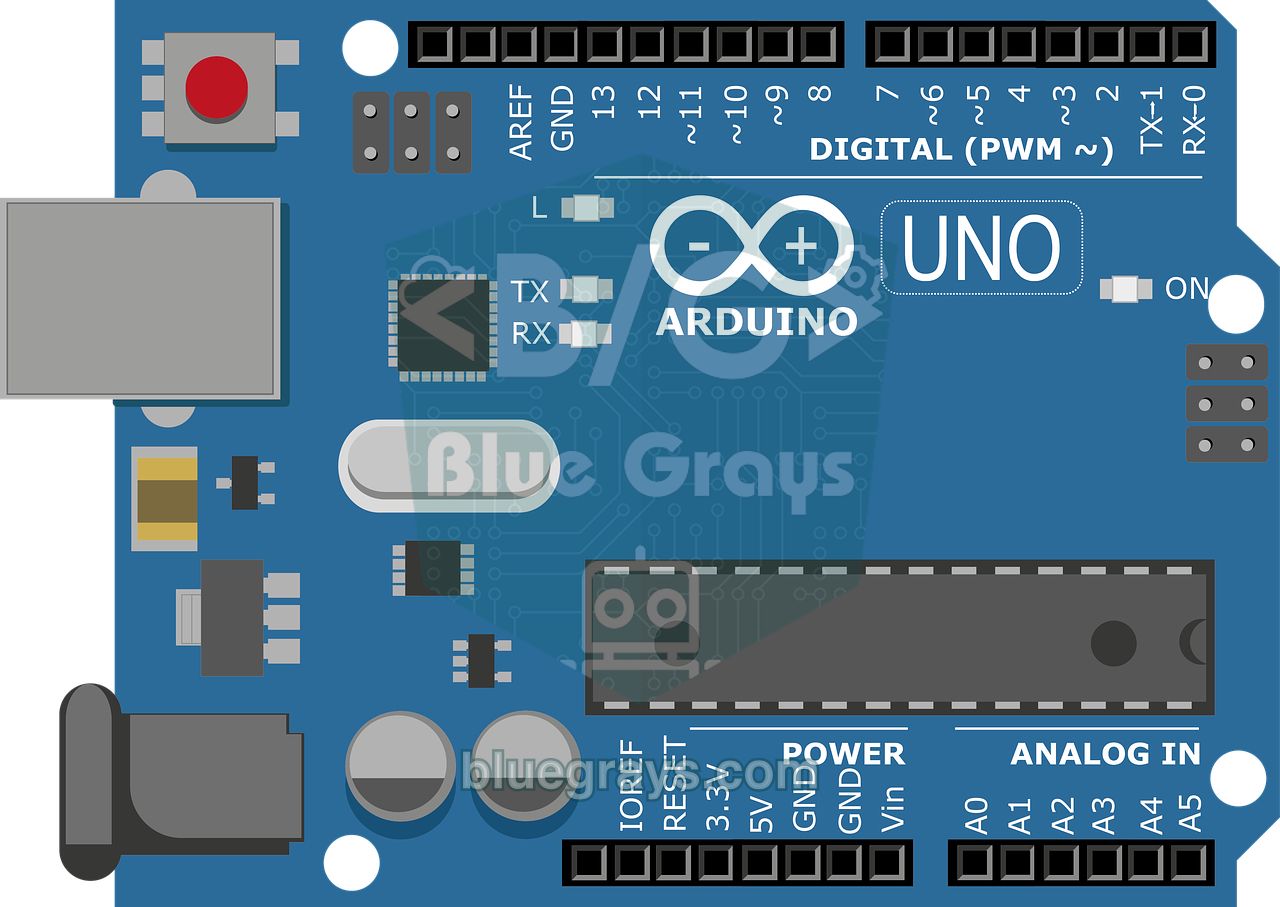
In the first example, board A sends the value of a potentiometer on A0 to board B ten times a second, and board B sets the brightness of the LED on D9 accordingly. Both boards use SoftwareSerial on D10 (RX) and D11 (TX), which keeps the USB connection and Serial Monitor free. Because the values are sent with println(), each number ends with the "\r\n" (line end) characters; the receiver knows the number is complete when it sees them. Wiring: A's D11 to B's D10, A's D10 to B's D11, and the grounds together.
1#include <SoftwareSerial.h>
2
3SoftwareSerial link(10, 11);    // RX = 10, TX = 11 (diğer karta / to the other board)
4
5void setup() {
6  Serial.begin(9600);           // USB: bilgisayar / computer
7  link.begin(9600);             // iki tarafta aynı baud / same baud on both sides
8}
9
10void loop() {
11  int deger = analogRead(A0);   // potansiyometre 0-1023 / potentiometer 0-1023
12  link.println(deger);          // ör. "512\r\n" / e.g. "512\r\n"
13  Serial.println(deger);
14  delay(100);                   // saniyede 10 ölçüm / 10 readings per second
15}
161#include <SoftwareSerial.h>
2
3SoftwareSerial link(10, 11); // RX = 10, TX = 11
4const int LED_PIN = 9; // PWM pini / PWM pin
5
6char tampon[8]; // en fazla 7 karakter + '\0' / up to 7 chars + '\0'
7byte konum = 0;
8
9void setup() {
10 Serial.begin(9600);
11 link.begin(9600);
12 pinMode(LED_PIN, OUTPUT);
13}
14
15void loop() {
16 while (link.available()) { // gelen her baytı oku / read every incoming byte
17 char c = link.read();
18 if (c == '\n') { // satır bitti / line complete
19 tampon[konum] = '\0';
20 int deger = atoi(tampon);
21 analogWrite(LED_PIN, map(deger, 0, 1023, 0, 255));
22 Serial.println(deger);
23 konum = 0;
24 } else if (c != '\r' && konum < sizeof(tampon) - 1) {
25 tampon[konum++] = c; // satıra ekle / append to the line
26 }
27 }
28}
29There are two things to notice in the receiver code. First, data never arrives "in one piece": "512" arrives as three separate bytes, about 1 millisecond apart. That's why we collect the bytes in a buffer and convert them to a number when the line end arrives. Second, the code never waits: functions like readString() or parseInt() wait 1 second by default when no data comes and slow your program down. Reading bytes as they arrive is the most reliable and fastest approach. We also limit the buffer size so corrupted data can't be written past the end of the array.
Two-way communication: command and reply
Real projects usually need a two-way conversation: one board sends a command, the other carries it out and replies. In the example below, board A works as a bridge: it forwards every character you type in the Serial Monitor to B and prints every character coming from B. Board B understands the commands "LED ON", "LED OFF" and "DURUM?" (status), replies to each one, and also reports on its own when the button on D2 is pressed. Don't forget to set the Serial Monitor line ending to Newline; B uses that character to know the command has ended.
1#include <SoftwareSerial.h>
2
3SoftwareSerial link(10, 11);    // RX = 10, TX = 11
4
5void setup() {
6  Serial.begin(9600);
7  link.begin(9600);
8  Serial.println("Komut yaz / type a command: LED ON, LED OFF, DURUM?");
9}
10
11void loop() {
12  if (Serial.available()) link.write(Serial.read());   // bilgisayar -> B kartı / computer -> board B
13  if (link.available()) Serial.write(link.read());     // B kartı -> bilgisayar / board B -> computer
14}
151#include <SoftwareSerial.h>
2
3SoftwareSerial link(10, 11); // RX = 10, TX = 11
4const int LED_PIN = 13; // kart üstündeki LED / on-board LED
5const int BUTON_PIN = 2; // buton GND'ye / button to GND
6
7String satir = "";
8int oncekiButon = HIGH;
9
10void komutCalistir(String k) {
11 k.trim(); // \r ve boşlukları at / strip \r and spaces
12 if (k == "LED ON") {
13 digitalWrite(LED_PIN, HIGH);
14 link.println("OK LED=1");
15 } else if (k == "LED OFF") {
16 digitalWrite(LED_PIN, LOW);
17 link.println("OK LED=0");
18 } else if (k == "DURUM?") { // durum sorgusu / status query
19 link.print("LED=");
20 link.print(digitalRead(LED_PIN));
21 link.print(" BUTON=");
22 link.println(digitalRead(BUTON_PIN) == LOW ? 1 : 0);
23 } else {
24 link.print("HATA / unknown: ");
25 link.println(k);
26 }
27}
28
29void setup() {
30 link.begin(9600);
31 pinMode(LED_PIN, OUTPUT);
32 pinMode(BUTON_PIN, INPUT_PULLUP);
33 satir.reserve(32);
34}
35
36void loop() {
37 while (link.available()) {
38 char c = link.read();
39 if (c == '\n') {
40 komutCalistir(satir);
41 satir = "";
42 } else if (satir.length() < 31) {
43 satir += c;
44 }
45 }
46
47 int buton = digitalRead(BUTON_PIN); // değişince kendiliğinden bildir / report changes unprompted
48 if (buton != oncekiButon) {
49 oncekiButon = buton;
50 link.println(buton == LOW ? "BUTON BASILDI / pressed" : "BUTON BIRAKILDI / released");
51 delay(20); // basit debounce / simple debounce
52 }
53}
54The trim() call on board B removes the \r character that arrives when the Serial Monitor is set to "Both NL & CR", along with extra spaces, so commands are recognised with either setting. Using reserve(32) for the String object prevents memory from being reallocated every time a character is added and reduces fragmentation of the Uno's 2 KB of RAM. This structure is also the basis for talking to the Arduino from a Python program on your computer; details in the Arduino Python serial communication post.
The limits of SoftwareSerial
SoftwareSerial imitates a UART in software instead of hardware: the processor times every bit itself. That's very handy, but it has a cost. While transmitting, interrupts are disabled for the whole of each byte; at 9600 baud that's about 1 millisecond per byte, during which millis() can drift, servo pulses can jitter and data arriving on another serial port can be lost. Only one SoftwareSerial port can listen at a time; if you open a second one, you have to choose which one listens with listen(). On boards like the Mega and Leonardo, only certain pins with interrupt support can be used as RX.
| Feature | Hardware UART (Serial) | SoftwareSerial | AltSoftSerial |
|---|---|---|---|
| Pins on the Uno | D0 (RX), D1 (TX), shared with USB | Almost any pin (PCINT for RX) | Fixed: D8 (RX), D9 (TX) |
| Highest reliable speed | 1–2 Mbaud | 57600 baud (115200 is marginal) | Stable at moderate speeds (9600–38400) |
| CPU load | Very low (hardware buffer) | High, interrupts off while sending | Medium, uses Timer1 |
| Send and receive at the same time | Yes | No | Yes |
| More than one port | 4 on the Mega | Only one listens at a time | Single port |
| Conflicts | Uploading and Serial Monitor | Timing-sensitive libraries like Servo, NeoPixel | D10 PWM and Servo (Timer1) |
Matching 5V and 3.3V levels
In UART, the "HIGH" level is the board's operating voltage: 5 V on the Arduino Uno, 3.3 V on the ESP32, Raspberry Pi Pico, ESP-01 and most newer modules. Connecting a 5 V TX output directly to a 3.3 V RX input exposes the input to overvoltage and damages the pin over time or immediately; the ESP32 and the RP2040-based Pico are not 5 V tolerant. The other direction is usually fine: the Uno treats 3.0 V and above as HIGH, so it can read a 3.3 V TX, but because that's close to the limit, a level shifter is more robust on long wires.
| Connection | What you need | Example |
|---|---|---|
| Uno TX (5 V) → ESP32 / Pico RX (3.3 V) | Voltage divider or level shifter | 1 kΩ in series + 2 kΩ to GND: 5 × 2/3 ≈ 3.3 V |
| ESP32 / Pico TX (3.3 V) → Uno RX (5 V) | Usually direct | The Uno counts above 3.0 V as HIGH |
| Uno TX → HC-05 RX | Voltage divider recommended | The HC-05 RX is a 3.3 V level input |
| Uno TX → SIM800L RX | Voltage divider | The SIM800L signal level is around 2.8 V |
| Both boards 5 V or both 3.3 V | Direct | Uno ↔ Nano, ESP32 ↔ Pico |
ESP32 UART: Serial, Serial1 and Serial2
The ESP32 has three hardware UARTs, and the best part is that thanks to its GPIO matrix the UART pins can be moved to almost any pin you like. UART0 (Serial) is connected to the USB-serial chip and used for the Serial Monitor. UART2 (Serial2) sits on GPIO 16 (RX) and 17 (TX) by default. UART1's old default pins (GPIO 9 and 10) are connected to the board's flash memory and can't be used directly, so always start Serial1 with pins: begin(baud, SERIAL_8N1, RX, TX). The code below builds a two-way bridge between the Serial Monitor and a device on UART2 (a GPS, another Arduino, a sensor); it's ideal for watching a GPS module's NMEA sentences.
| UART | Arduino name | Default RX / TX | Note |
|---|---|---|---|
| UART0 | Serial | GPIO 3 / GPIO 1 | Connected to the USB-serial chip, uploading and Serial Monitor |
| UART1 | Serial1 | GPIO 9 / GPIO 10 (flash, don't use) | Pass other pins in begin(), e.g. 25 / 26 |
| UART2 | Serial2 | GPIO 16 / GPIO 17 | On WROVER boards 16/17 are used by PSRAM, pick other pins |
1// ESP32: UART0 = Serial (USB), UART2 = Serial2 (GPIO 16/17)
2const int RXD2 = 16;            // karşı cihazın TX'i buraya / the other device's TX goes here
3const int TXD2 = 17;            // karşı cihazın RX'ine / to the other device's RX
4
5void setup() {
6  Serial.begin(115200);                          // USB Seri Monitör / USB Serial Monitor
7  Serial2.begin(9600, SERIAL_8N1, RXD2, TXD2);   // baud, çerçeve, RX, TX / baud, frame, RX, TX
8  // UART1'i de istediğin pinlere taşıyabilirsin / UART1 can be moved to any free pins:
9  // Serial1.begin(115200, SERIAL_8N1, 25, 26);
10  Serial.println("UART2 hazir / ready");
11}
12
13void loop() {
14  while (Serial2.available()) Serial.write(Serial2.read());   // UART2 -> USB
15  while (Serial.available()) Serial2.write(Serial.read());    // USB -> UART2
16}
17
The ESP32's UARTs can go up to 5 Mbaud and each has a hardware buffer; the default receive buffer is 256 bytes and can be enlarged before begin() with a call like Serial2.setRxBufferSize(1024). This matters for GPS modules that send dozens of sentences a second or GSM modules with long replies. Since the ESP32's pins are 3.3 V, don't forget the divider from the previous section when connecting a 5 V Arduino. You can see the ESP32 pinout in the Pinout tool.
Raspberry Pi Pico UART pins and MicroPython
The Raspberry Pi Pico has two hardware UARTs (uart0 and uart1), and each can be routed to several different pin pairs. In MicroPython, the REPL and print() output come over a separate virtual serial port on USB, so UART0 is completely free; there's no need to unplug wires when uploading code as on the Arduino. The Pico's pins are 3.3 V and on the RP2040-based Pico they are not 5 V tolerant. The code below does on the Pico what board B did on the Arduino: it reads lines from UART0, turns the on-board LED on or off with the "LED ON" and "LED OFF" commands and replies. If you want it to talk to the Uno bridge sketch, don't forget a voltage divider on the Uno's TX line.
| UART | TX pins | RX pins | MicroPython example |
|---|---|---|---|
| uart0 | GP0, GP12, GP16 | GP1, GP13, GP17 | UART(0, 9600, tx=Pin(0), rx=Pin(1)) |
| uart1 | GP4, GP8 | GP5, GP9 | UART(1, 9600, tx=Pin(4), rx=Pin(5)) |
1from machine import UART, Pin
2import time
3
4uart = UART(0, baudrate=9600, tx=Pin(0), rx=Pin(1))   # UART0: GP0 = TX, GP1 = RX
5led = Pin("LED", Pin.OUT)                             # Pico ve Pico W dahili LED / on-board LED
6
7tampon = b""
8while True:
9    if uart.any():
10        tampon += uart.read()                         # gelen baytlar / incoming bytes
11        while b"\n" in tampon:                        # her tam satırı işle / handle each full line
12            satir, tampon = tampon.split(b"\n", 1)
13            try:
14                komut = satir.decode().strip()
15            except UnicodeError:
16                continue                              # bozuk bayt: atla / corrupt byte: skip
17            if komut == "LED ON":
18                led.on()
19                uart.write("OK LED=1\n")
20            elif komut == "LED OFF":
21                led.off()
22                uart.write("OK LED=0\n")
23            else:
24                uart.write("HATA / unknown: " + komut + "\n")
25    if len(tampon) > 64:                              # satır sonu hiç gelmezse taşmayı önle / avoid overflow
26        tampon = b""
27    time.sleep_ms(5)
28
Packet framing: start and end characters
UART is a stream of bytes; it doesn't know where anything starts or ends. When the sender writes "23.5,48,812", the receiver may have started listening halfway through, a byte may have been lost to noise, or two readings may run together. The solution is to turn the data into a packet: if every packet starts with "<" and ends with ">", the receiver ignores everything until the first "<", processes the packet when ">" arrives and throws away any half packets in between. All the sender has to do is print the values between Serial.print('<'), commas and Serial.print('>'). You can try the receiver code below straight away by typing <23.5,48,812> in the Serial Monitor.
1// Paket biçimi / packet format: <sicaklik,nem,isik>  ör. / e.g. <23.5,48,812>
2const byte MAKS = 32;
3char tampon[MAKS];
4byte konum = 0;
5bool paketIcinde = false;                    // '<' görüldü mü? / have we seen '<'?
6
7void paketiIsle(char* p) {
8  char* parca = strtok(p, ",");              // ilk alan / first field
9  if (!parca) return;
10  float sicaklik = atof(parca);
11  parca = strtok(NULL, ",");
12  if (!parca) return;                        // eksik alan: paketi at / missing field: drop
13  int nem = atoi(parca);
14  parca = strtok(NULL, ",");
15  if (!parca) return;
16  int isik = atoi(parca);
17
18  Serial.print("Sicaklik / temp: ");
19  Serial.print(sicaklik, 1);
20  Serial.print("  Nem / humidity: ");
21  Serial.print(nem);
22  Serial.print("  Isik / light: ");
23  Serial.println(isik);
24}
25
26void setup() {
27  Serial.begin(9600);                        // Seri Monitör'den <23.5,48,812> yazarak dene / test from the Serial Monitor
28}
29
30void loop() {
31  while (Serial.available()) {
32    char c = Serial.read();
33    if (c == '<') {                          // yeni paket başladı / a new packet starts
34      paketIcinde = true;
35      konum = 0;
36    } else if (c == '>' && paketIcinde) {    // paket bitti / packet complete
37      tampon[konum] = '\0';
38      paketIcinde = false;
39      paketiIsle(tampon);
40    } else if (paketIcinde) {
41      if (konum < MAKS - 1) tampon[konum++] = c;
42      else paketIcinde = false;              // çok uzun, bozuk: at / too long, corrupt: drop
43    }                                        // paket dışındaki baytlar yok sayılır / bytes outside packets are ignored
44  }
45}
46| Method | Example | Pros | Cons |
|---|---|---|---|
| Text with line endings | 512\n | Simplest, readable in the Serial Monitor | Mid-line you can't tell where it starts |
| Start and end characters | <23.5,48,812> | Recovers by itself after losing sync | Can't use < and > inside the data |
| Text with checksum (like NMEA) | $GPGGA,...*47 | Corrupted packets are detected | A bit more calculation and code |
| Binary packet | 0xAA, length, data, CRC | Shortest and fastest | Hard to read and debug |
In noisy environments or with long wires, you can go a step further and add a checksum to the packet. The NMEA format used by GPS modules is a good example: all characters between "$" and "*" are XORed together and the result is written at the end as a two-digit hexadecimal number. The receiver does the same calculation and drops the packet if it doesn't match. That protects you from sneaky errors such as a corrupted "812" being processed as "872".
UART project ideas
- Phone control: the HC-05 Bluetooth module is really a wireless UART; control an LED, a relay or a robot car from your phone with the HC-05.
- GPS logging: parse the NMEA sentences a NEO-6M GPS module sends over UART and write the position to an SD card.
- Two-board system: connect an Uno that reads the sensors to an ESP32 that sends the data to the internet over Wi-Fi, via UART.
- SMS alarm: send AT commands to a SIM800L module over UART and text yourself when a door opens.
- Computer control panel: send commands to the Arduino from a desktop app written in Python and plot the sensor data.
- MP3 player: choose tracks, set the volume and play voice alerts over UART with a DFPlayer Mini.
Common mistakes and fixes
| Symptom | Likely cause | Fix |
|---|---|---|
| Garbage characters in the Serial Monitor | Baud rates don't match | Use the same baud rate in the code and the Serial Monitor |
| No data at all | TX wired to TX, RX to RX | Cross the wires: TX → RX, RX → TX |
| Random corrupted characters | GND not connected | Connect the grounds of both boards |
| Upload fails (not in sync) | A module is connected to D0/D1 | Unplug the wires while uploading or use SoftwareSerial |
| Commands aren't recognised | Line ending is \r\n or missing | Set the Serial Monitor to Newline and clean the text with trim() |
| The end of long messages goes missing | The 64-byte buffer overflowed | Avoid delay(), read data as it arrives, lower the rate |
| ESP32 RX pin doesn't work or is damaged | 5 V TX connected directly | Add a voltage divider or level shifter |
| SoftwareSerial fails at 115200 | Software timing can't keep up | Use 57600 or lower, or switch to a hardware UART |
UART is the first communication method to learn in electronics: two wires, a common GND and the same baud rate are all it takes, and when set up correctly it works for years without trouble. Once you've got crossover wiring, level matching and packet framing down, you can use dozens of modules from GPS to GSM with ease. In the BlueGrays app you'll find step-by-step projects with circuit diagrams and code for one-way and two-way communication between two Arduinos, lighting an LED from your phone over Bluetooth and a Bluetooth-controlled car.
Frequently asked questions
What does UART stand for and what is it used for?
UART stands for Universal Asynchronous Receiver-Transmitter. It lets two devices exchange data byte by byte without a clock line, using only TX and RX wires and a baud rate agreed in advance. The Arduino Serial Monitor, GPS, Bluetooth and GSM modules all use UART.
How do you connect TX and RX?
One device's TX pin goes to the other's RX pin, and its RX pin to the other's TX pin, so the connection is crossed. The GND pins of both devices must also be connected. Connecting TX to TX blocks the data completely.
What is baud rate and which one should I choose?
Baud rate is the number of bits sent per second and must be the same on both sides. The most common values with Arduino modules are 9600 and 115200; 9600 is the default for most GPS and Bluetooth modules, while 115200 is preferred for the ESP32 and fast output. Start with the default rate in the module's documentation.
Is UART the same as a serial port?
In everyday use they often mean the same thing. UART is the hardware unit that serialises data; a serial port is the COM or /dev/tty connection on a computer. RS-232 and RS-485 are standards that use different voltage levels to carry UART signals over longer distances.
How can I use more than one UART on an Arduino?
The Uno has a single hardware UART shared with USB; for extra ports you use SoftwareSerial, but only one can listen at a time. The Arduino Mega has three extra hardware UARTs (Serial1, Serial2 and Serial3), the ESP32 has three in total and the Raspberry Pi Pico has two.
How long can a UART cable be?
TTL-level UART at 3.3 V or 5 V works reliably up to a few metres at low baud rates, and the distance shrinks as the speed goes up. For longer runs, RS-485 transceivers (such as the MAX485) reach hundreds of metres, and RS-232 about 15 metres.
Projects to build after reading this
See all projects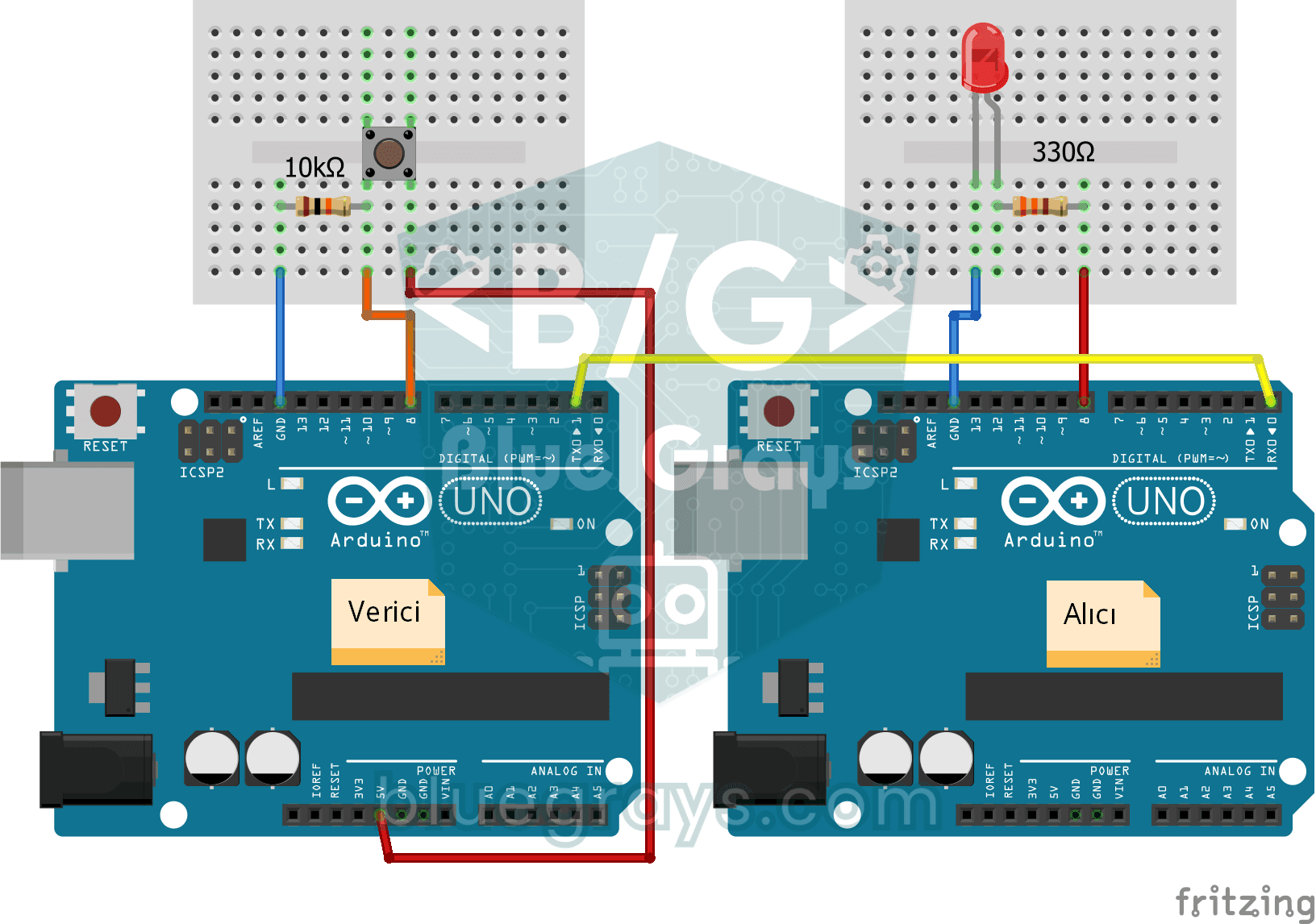
One-Way Communication Between 2 Arduinos
You get two Arduinos talking over a single wire: press the button on one and the LED on the other lights up, press it again and it goes off. The sending board reports the button press with a short mes
Two-Way Communication Between 2 Arduinos
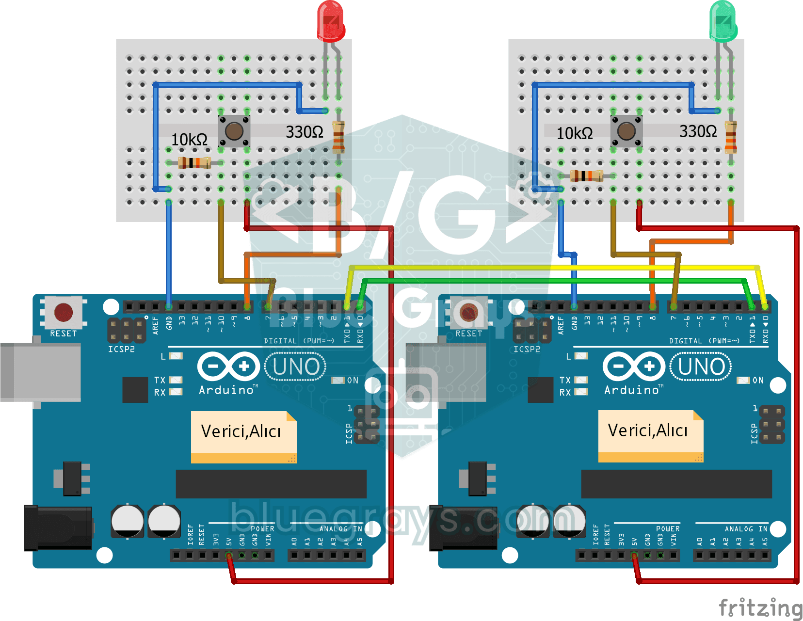
Two Arduinos are wired together and talk to each other: press the button on one and the light on the other comes on, press it again and it goes off. Both boards run the same program, so each one both
Control an LED from Your Phone via Bluetooth
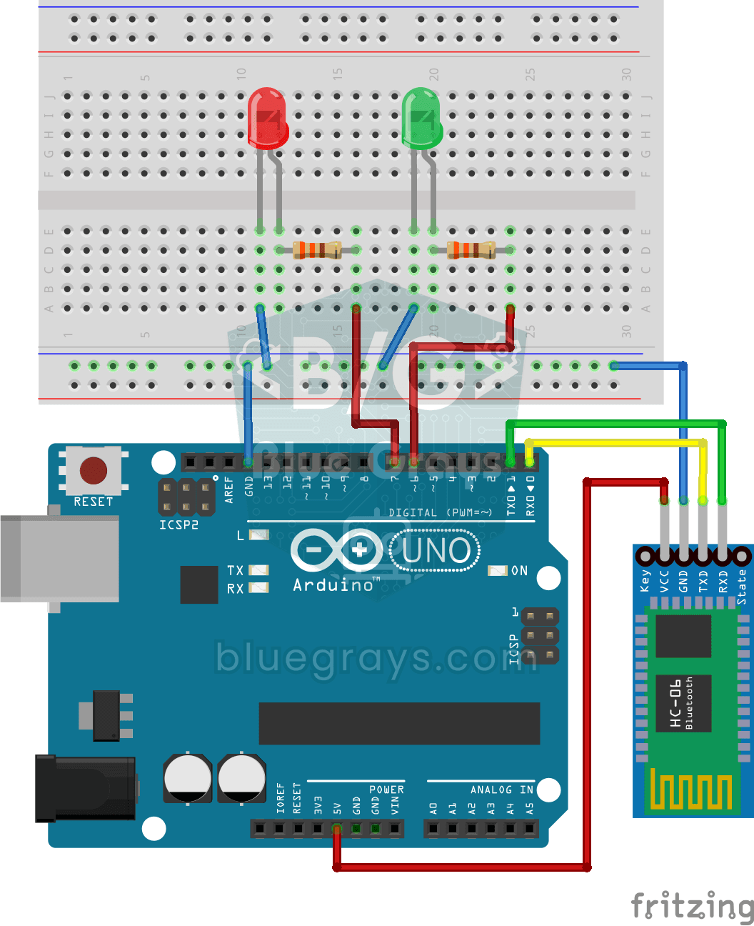
A small rehearsal for switching the lights in your room on and off from your phone. The Bluetooth module passes the letters sent from your phone to the Arduino; one letter turns on the red LED, anothe

Bluetooth Controlled Car with L298N
Turn your phone into a remote and drive your own robot car. The Arduino receives commands from a remote-control app on your phone through a Bluetooth module and spins the wheels with a motor driver; t
Python Developer Keyboard
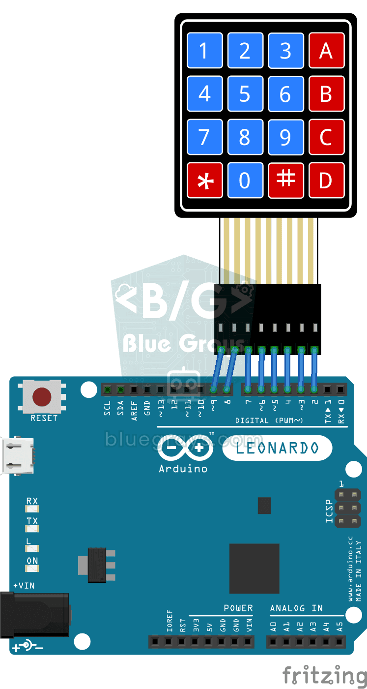
If you are tired of typing the same patterns over and over while coding, this little keyboard is made for you. The Arduino Leonardo connects to your computer just like a keyboard, and each key on the
HC-SR04 Distance Measurement (Serial Display)
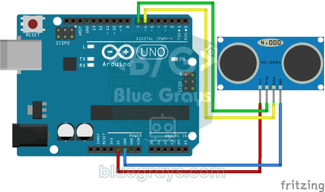
The HC-SR04 sensor works just like a bat finding its way in the dark: it sends out a sound you cannot hear, listens for the echo and measures how far away the object in front of it is. The Arduino wri
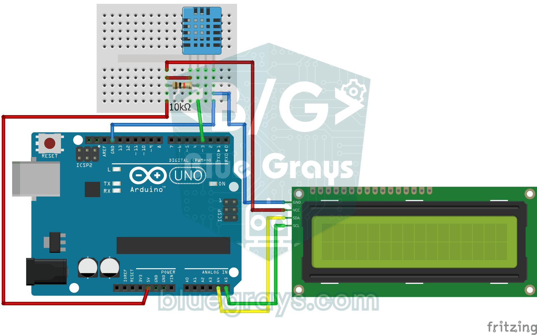
Temperature and Humidity with DHT11
How warm is your room, and is the air humid or dry? The DHT11 sensor measures temperature and humidity, and the Arduino writes the values on a two-line LCD screen, refreshing every couple of seconds.

Reading Light Intensity with the ESP32 LDR Module
Real-time monitoring of the LDR module's raw ADC value and relative light percentage calculated from dark and light reference values in the Serial Monitor. This percentage is not a lux measurement. Teaches the module’s calibration logic. It is ideal to complete this before Project 10, as it is used to determine the threshold value.