
2.4 TFT LCD Shield Arduino Guide: MCUFRIEND_kbv, Touch and SD
2.4 TFT LCD shield on Arduino: MCUFRIEND_kbv setup, reading the driver ID, fixing the white screen, touch calibration, buttons, BMP images from SD and pins.
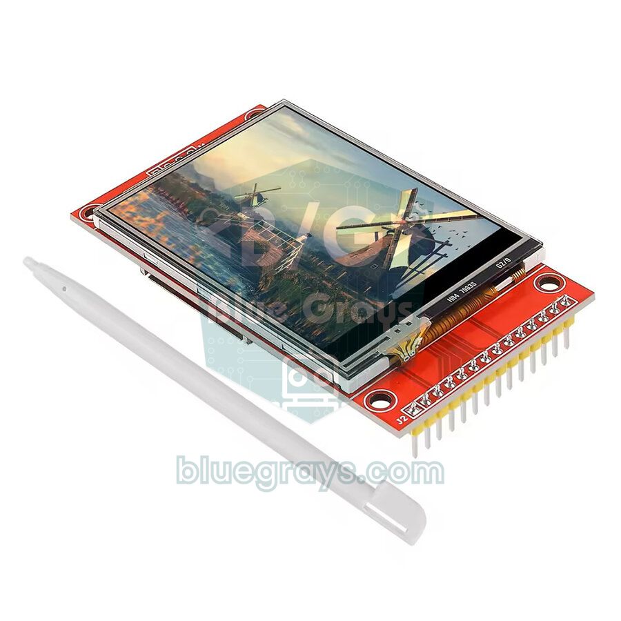
The 2.4 TFT LCD shield for Arduino is a 240×320-pixel colour touchscreen that plugs straight onto an Arduino Uno. No wires, no soldering: you seat the shield on the headers of an Uno or Mega, install the right library and within minutes you're showing coloured text, shapes, touch buttons and pictures from the SD card. It's cheap, so it turns up in countless starter kits and school projects; for the same reason it's one of the parts people most often ask about online with "why is my screen just white?".
In this guide you'll see why the shield sometimes shows a white screen and how the MCUFRIEND_kbv library fixes it. You'll find the driver ID, calibrate the touch panel, fix touch that works backwards, control an LED with on-screen buttons and show images from a microSD card. We also cover which pins the shield takes, which ones are left over and what to watch out for on the Mega, the ESP32 and the Pico.
What is the 2.4" TFT shield and how does it work?
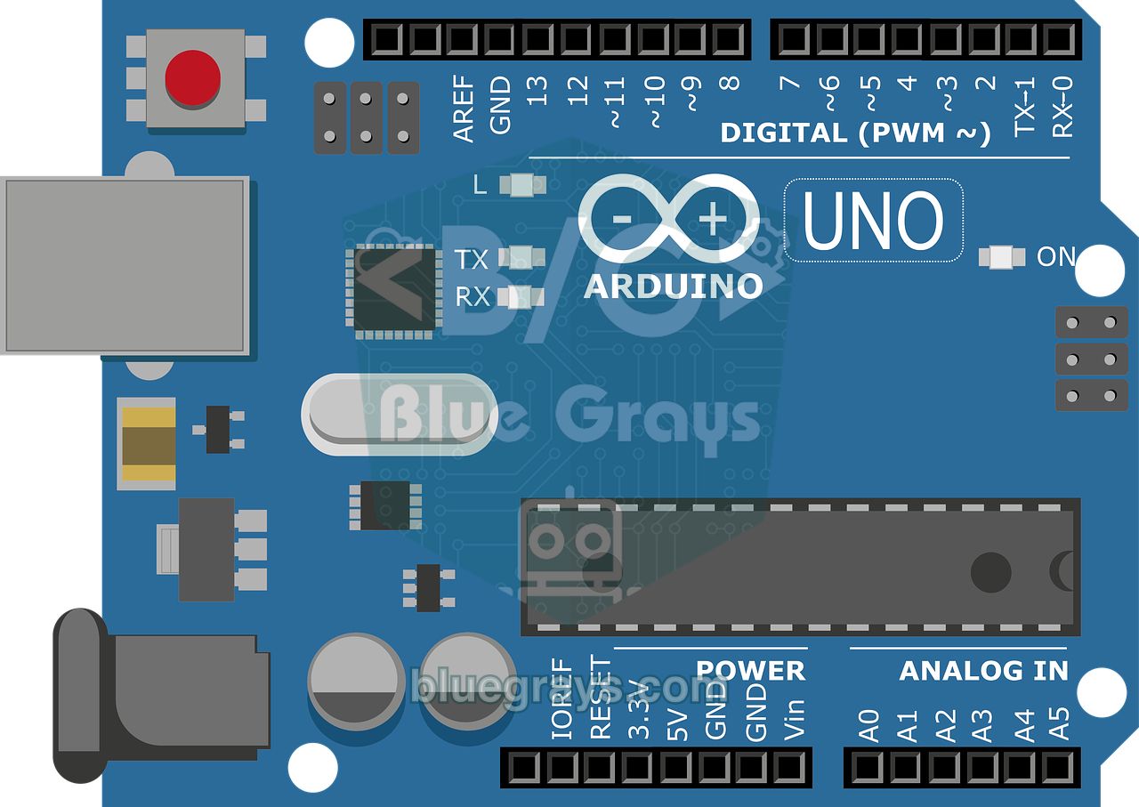
The shield has three parts: the colour TFT panel, a resistive touch layer glued on top of it and a microSD card slot on the back. The display isn't connected over a serial bus like SPI but over an 8-bit parallel bus; because it sends a whole byte at a time, it draws faster on an Uno than SPI modules do, but it uses a lot of pins. The panel's driver chip runs at 3.3 V; thanks to the 3.3 V regulator and a 74HC245-style level shifter on the board, the Uno's 5 V signals are safe to use.
| Feature | Value |
|---|---|
| Display | 2.4-inch TFT, 240×320 pixels |
| Colour | 16-bit (RGB565), 65,536 colours |
| Interface | 8-bit parallel (D0–D7) + 5 control lines |
| Driver chip | Varies: ILI9341, ILI9325, ST7781, SPFD5408, HX8347 and others |
| Touch | 4-wire resistive, shares pins with the display |
| SD slot | microSD over SPI (D10–D13) |
| Supply | 5 V (3.3 V regulator on the board) |
| Current | About 80–120 mA, mostly for the backlight |
| Compatible boards | Arduino Uno, Arduino Mega 2560 |
Shield or SPI module?
Two different products of the same size are sold, and both get called a "2.4 TFT". The shield is the parallel model you plug onto an Uno and go. The SPI module has a single row of header pins along one edge and is wired up with jumper leads; its touch panel is usually read over SPI with an XPT2046 chip. This guide covers the shield; for the SPI module, see our ILI9341 TFT display guide.
| Feature | 2.4" Uno shield | 2.4" SPI module |
|---|---|---|
| Connection | Plugs onto an Uno or Mega, no wires | 7 to 14 jumper wires |
| Pins used | D2–D9, A0–A4 (D10–D13 with SD) | 5 for the display, 8–9 with touch and SD |
| Drawing speed on an Uno | Fast (parallel) | Slower (SPI) |
| Library | MCUFRIEND_kbv | Adafruit_ILI9341, TFT_eSPI |
| Touch reading | Analog, pins shared with the display | XPT2046 chip over SPI |
| ESP32 and Pico | Not suitable | Suitable |
| Spare pins for sensors | Almost none | Plenty |
Pin table: which pins does the shield use?
| Shield pin | Arduino Uno pin | Function |
|---|---|---|
| LCD_RD | A0 | Read strobe |
| LCD_WR | A1 | Write strobe (may be shared with touch) |
| LCD_RS (CD) | A2 | Command or data? (shared with touch) |
| LCD_CS | A3 | Display chip select (may be shared with touch) |
| LCD_RST | A4 | Display reset |
| LCD_D0, LCD_D1 | D8, D9 | First two bits of the data bus |
| LCD_D2–LCD_D7 | D2–D7 | Remaining six bits of the data bus |
| SD_SS / SD_DI / SD_DO / SD_SCK | D10 / D11 / D12 / D13 | microSD card (SPI) |
| 5V, 3V3, GND | 5V, 3.3V, GND | Power |
Installing the MCUFRIEND_kbv library
- Open the Library Manager in the Arduino IDE, search for MCUFRIEND_kbv and install it.
- From the same place, install Adafruit GFX Library; the text, line, circle and button functions come from it.
- For touch, install the Adafruit TouchScreen library (it's included in code as TouchScreen.h).
- For the SD card you don't need to install anything; the SD library ships with the Arduino IDE.
Why MCUFRIEND_kbv? These shields may look identical but can have different driver chips inside: two shields bought from the same seller two months apart may turn out to be an ILI9341 and an ST7781. Older libraries such as Adafruit_TFTLCD or SPFD5408 only know a few chips; if the chip doesn't match, the display is never initialised and you get the famous white screen. MCUFRIEND_kbv first asks the chip for its ID and then sends the start-up commands that suit that chip.
Finding the driver ID: readID()
The first job is to ask your shield who it is. The code below prints the ID to the Serial Monitor and to the screen, then draws three coloured boxes. Set the Serial Monitor to 9600 baud.
1#include <Adafruit_GFX.h>
2#include <MCUFRIEND_kbv.h>
3
4MCUFRIEND_kbv tft;
5
6void setup() {
7  Serial.begin(9600);
8  uint16_t id = tft.readID();                 // sürücü kimliğini oku / read the driver ID
9  Serial.print(F("TFT ID = 0x"));
10  Serial.println(id, HEX);
11  if (id == 0xD3D3) id = 0x9341;              // salt yazılır shield: kimliği elle ver / write-only shield: set the ID by hand
12  tft.begin(id);
13  tft.setRotation(1);                         // yatay, 320x240 / landscape, 320x240
14  tft.fillScreen(0x0000);                     // siyah / black
15  tft.setTextColor(0xFFFF);                   // beyaz / white
16  tft.setTextSize(3);
17  tft.setCursor(20, 20);
18  tft.print(F("BlueGrays"));
19  tft.setTextSize(2);
20  tft.setCursor(20, 70);
21  tft.print(F("ID: 0x"));
22  tft.print(id, HEX);
23  tft.fillRect(20, 120, 80, 60, 0xF800);      // kırmızı / red
24  tft.fillRect(120, 120, 80, 60, 0x07E0);     // yeşil / green
25  tft.fillRect(220, 120, 80, 60, 0x001F);     // mavi / blue
26}
27
28void loop() {
29}| ID read | Chip | What to do |
|---|---|---|
| 0x9341 | ILI9341 | The most common model; works straight away |
| 0x9325 / 0x9328 | ILI9325 / ILI9328 | Older but reliable; works straight away |
| 0x7783 | ST7781 | Works straight away |
| 0x5408 | SPFD5408 | Works straight away; no need for the old SPFD5408 library |
| 0x4747 / 0x9595 | HX8347-D / HX8347-I | Works straight away |
| 0x1505 / 0x0154 | R61505 / S6D0154 | Works straight away |
| 0xD3D3 | Shield with no read line connected | Write the ID into the code by hand; on a 2.4" try 0x9341 first |
| 0x0000 or 0xFFFF | No response | Shield not fully seated, a bent pin or a faulty board |
If the boxes come out red, green and blue in that order, all is well. If you see blue instead of red, you probably set the ID by hand and the wrong start-up commands were sent, so use the value readID found. If the colours look like a negative, add the line tft.invertDisplay(true) after begin. If the ID is something odd, the library's File > Examples > MCUFRIEND_kbv > LCD_ID_readreg example dumps all the chip's registers, and that output is the quickest way to understand the problem. The graphictest_kbv example tests every display function in one go.
The white screen and other display problems
A white screen is actually a clue: the backlight has power but the driver chip was never initialised. When the panel gets no commands, its pixels let the light through and the whole screen looks white. Work through the table from top to bottom:
| Symptom | Likely cause | Fix |
|---|---|---|
| White screen with an old library | The library doesn't know your chip | Install MCUFRIEND_kbv and start it with readID |
| White screen, ID 0x0000 or 0xFFFF | Shield not fully seated or a bent pin | Remove the shield, straighten the pins and press it all the way down |
| White screen, ID 0xD3D3 | No read line, so the ID can't be read | Set the ID by hand, e.g. tft.begin(0x9341); if that fails, try 0x9325 and 0x7783 |
| Negative colours (white looks black) | The chip's inversion setting differs | tft.invertDisplay(true) after begin |
| Red and blue swapped | The hand-set ID doesn't match the chip | Use the ID readID finds and update the library to the latest version |
| Mirrored text | The hand-set ID doesn't match the panel | Get the ID with readID; check all four orientations with the aspect_kbv example |
| The picture breaks up when you touch it | Reading touch left the shared pins as inputs | Set YP and XM back to OUTPUT after getPoint |
| Works on an Uno, white on a Mega | The library doesn't know the Mega's pin mapping | MCUFRIEND_kbv supports the Mega; remove the old library |
Calibrating the touch panel
A resistive touch panel is made of two thin resistive layers with a tiny gap between them. When you press, the layers touch; the library applies a voltage across one layer and reads the voltage on the other with an analog input, which gives it the X and Y position. Those readings are raw numbers, roughly 100 to 900, and they differ from panel to panel, so you need a calibration to turn them into pixels. The touch panel also shares pins with the display, and which four pins go to the touch layer changes from shield to shield.
- Open the TouchScreen_Calibr_native example from File > Examples > MCUFRIEND_kbv and upload it.
- Open the Serial Monitor at 9600 baud; the example first works out the touch pins by itself.
- Press the crosses that appear on screen one by one, holding your finger or stylus on each until the text changes.
- When it's done, two lines appear under the "COPY-PASTE" heading in the Serial Monitor: const int XP=...,XM=...,YP=...,YM=... and const int TS_LEFT=...,TS_RT=...,TS_TOP=...,TS_BOT=....
- Paste those two lines over the example values at the top of the sketches below.
1#include <Adafruit_GFX.h>
2#include <MCUFRIEND_kbv.h>
3#include <TouchScreen.h>
4
5MCUFRIEND_kbv tft;
6
7// Kalibrasyon örneğinin çıktısını buraya yapıştır / paste the calibration sketch output here
8const int XP = 6, XM = A2, YP = A1, YM = 7;
9const int TS_LEFT = 907, TS_RT = 136, TS_TOP = 942, TS_BOT = 139;
10
11TouchScreen ts = TouchScreen(XP, YP, XM, YM, 300);   // 300 ohm X plakası / 300 ohm X plate
12const int MINPRESSURE = 200;
13const int MAXPRESSURE = 1000;
14
15bool readTouch(int &x, int &y) {
16  TSPoint p = ts.getPoint();
17  pinMode(YP, OUTPUT);                 // ortak pinleri ekrana geri ver / give the shared pins back to the display
18  pinMode(XM, OUTPUT);
19  digitalWrite(YP, HIGH);
20  digitalWrite(XM, HIGH);
21  if (p.z < MINPRESSURE || p.z > MAXPRESSURE) return false;
22  x = map(p.x, TS_LEFT, TS_RT, 0, tft.width());    // dikey yön için / for portrait
23  y = map(p.y, TS_TOP, TS_BOT, 0, tft.height());
24  return true;
25}
26
27void setup() {
28  tft.begin(tft.readID());
29  tft.setRotation(0);                  // dikey, kalibrasyonla aynı / portrait, same as calibration
30  tft.fillScreen(0x0000);
31  tft.fillRect(0, 0, 240, 30, 0x001F);
32  tft.setTextColor(0xFFFF);
33  tft.setTextSize(2);
34  tft.setCursor(10, 8);
35  tft.print(F("Ciz / Draw"));
36}
37
38void loop() {
39  int x, y;
40  if (readTouch(x, y)) {
41    if (y < 30) tft.fillRect(0, 30, 240, 290, 0x0000);   // başlığa dokun: temizle / tap the header: clear
42    else tft.fillCircle(x, y, 3, 0xFFE0);                 // sarı nokta / yellow dot
43  }
44}
This little drawing program is the best way to test your calibration: the dot should land almost exactly under your finger. p.z is the pressure; if it isn't between MINPRESSURE and MAXPRESSURE it doesn't count as a touch, which filters out light brushes and electrical noise. The pinMode lines inside readTouch() are crucial: while reading, the TouchScreen library turns the shared pins into analog inputs and leaves them that way; without these lines, later drawing commands never reach the display and the picture breaks up. A tip: a resistive panel works by pressure, so a fingernail or stylus draws more precisely than a fingertip.
| Symptom | Cause | Fix |
|---|---|---|
| Touching the right puts the dot on the left | X axis reversed | Swap the TS_LEFT and TS_RT values |
| Touching the top puts the dot at the bottom | Y axis reversed | Swap the TS_TOP and TS_BOT values |
| X and Y mixed up in landscape | setRotation(1) turned the axes | Map p.y for x and p.x for y, or stay in portrait |
| No touch detected at all | XP, XM, YP, YM are wrong | Run the calibration example again and use the pins it reports |
| Dots appear without touching | Pressure threshold too low | Raise MINPRESSURE to 300–400 |
| Dots land a few pixels off | The calibration was rushed | Recalibrate, pressing the exact centre of each cross for longer |
A touch button interface
The Adafruit_GFX_Button class in the Adafruit GFX library draws buttons with an outline and a label in a few lines, and it works out by itself whether a touch landed on the button. The code below switches an LED on A5 on and off with two buttons; we chose A5 because it's practically the only pin an Uno has left with the shield fitted. Don't forget to connect the LED through a 220 Ω resistor.
1#include <Adafruit_GFX.h>
2#include <MCUFRIEND_kbv.h>
3#include <TouchScreen.h>
4
5MCUFRIEND_kbv tft;
6const int XP = 6, XM = A2, YP = A1, YM = 7;                       // kendi değerlerin / your own values
7const int TS_LEFT = 907, TS_RT = 136, TS_TOP = 942, TS_BOT = 139;
8TouchScreen ts = TouchScreen(XP, YP, XM, YM, 300);
9
10const int LED_PIN = A5;               // shield'in boş bıraktığı pin / the pin the shield leaves unused
11Adafruit_GFX_Button onBtn, offBtn;
12char onLabel[] = "ON";
13char offLabel[] = "OFF";
14
15bool readTouch(int &x, int &y) {
16  TSPoint p = ts.getPoint();
17  pinMode(YP, OUTPUT);
18  pinMode(XM, OUTPUT);
19  digitalWrite(YP, HIGH);
20  digitalWrite(XM, HIGH);
21  if (p.z < 200 || p.z > 1000) return false;
22  x = map(p.x, TS_LEFT, TS_RT, 0, tft.width());
23  y = map(p.y, TS_TOP, TS_BOT, 0, tft.height());
24  return true;
25}
26
27void showState(bool on) {
28  tft.fillRect(20, 40, 200, 60, on ? 0x07E0 : 0x7BEF);  // yeşil ya da gri / green or grey
29  tft.setTextColor(0x0000);
30  tft.setTextSize(3);
31  tft.setCursor(50, 58);
32  tft.print(on ? F("LED ON") : F("LED OFF"));
33}
34
35void setup() {
36  pinMode(LED_PIN, OUTPUT);
37  tft.begin(tft.readID());
38  tft.setRotation(0);
39  tft.fillScreen(0x0000);
40  // merkez x, merkez y, genişlik, yükseklik, çerçeve, dolgu, yazı rengi, etiket, yazı boyu
41  // center x, center y, width, height, outline, fill, text colour, label, text size
42  onBtn.initButton(&tft, 120, 170, 160, 60, 0xFFFF, 0x07E0, 0x0000, onLabel, 3);
43  offBtn.initButton(&tft, 120, 260, 160, 60, 0xFFFF, 0xF800, 0xFFFF, offLabel, 3);
44  onBtn.drawButton();
45  offBtn.drawButton();
46  showState(false);
47}
48
49void loop() {
50  int x = 0, y = 0;
51  bool down = readTouch(x, y);
52  onBtn.press(down && onBtn.contains(x, y));
53  offBtn.press(down && offBtn.contains(x, y));
54  if (onBtn.justPressed()) {
55    onBtn.drawButton(true);             // basılı görünüm / pressed look
56    digitalWrite(LED_PIN, HIGH);
57    showState(true);
58  }
59  if (offBtn.justPressed()) {
60    offBtn.drawButton(true);
61    digitalWrite(LED_PIN, LOW);
62    showState(false);
63  }
64  if (onBtn.justReleased()) onBtn.drawButton();
65  if (offBtn.justReleased()) offBtn.drawButton();
66  delay(20);
67}
press() records on every pass whether the button is pressed at that moment; justPressed() returns true only on the first pass it's pressed and justReleased() only on the pass it's let go. That way the LED doesn't get the same command over and over while your finger stays on the button, and the screen isn't redrawn for nothing. drawButton(true) inverts the button's colours to give a pressed look. Connect a relay module to A5 instead of the LED and you can switch a lamp from the touchscreen; for safe wiring, see our relay module guide.
Showing pictures from the SD card
The microSD slot on the back is the easiest way to put full-colour pictures on the screen. On your computer, resize the image to 240×320 (portrait) and save it as a 24-bit BMP: in Paint choose "24-bit Bitmap", in GIMP pick the 24-bit option when exporting. Keep the file name to 8 characters at most (for example CAT.BMP), because the SD library works with short names, and change "KEDI.BMP" in the code to your file's name. Format the card as FAT32 or FAT16; cards larger than 32 GB usually come as exFAT and won't be recognised.
1#include <SPI.h>
2#include <SD.h>
3#include <Adafruit_GFX.h>
4#include <MCUFRIEND_kbv.h>
5
6MCUFRIEND_kbv tft;
7const int SD_CS = 10;                 // shield üzerindeki SD seçme pini / SD chip select on the shield
8const byte CHUNK = 20;                // tek seferde okunan piksel / pixels read per step (az RAM / low RAM)
9
10uint16_t read16(File &f) { uint16_t v; f.read((uint8_t *)&v, 2); return v; }
11uint32_t read32(File &f) { uint32_t v; f.read((uint8_t *)&v, 4); return v; }
12
13bool drawBMP(const char *name, int x, int y) {
14  File bmp = SD.open(name);
15  if (!bmp) return false;
16  if (read16(bmp) != 0x4D42) { bmp.close(); return false; }   // "BM" imzası / "BM" signature
17  read32(bmp); read32(bmp);                                   // dosya boyutu, ayrılmış / file size, reserved
18  uint32_t offset = read32(bmp);                              // piksel verisinin başı / start of pixel data
19  read32(bmp);                                                // başlık boyutu / header size
20  int32_t w = read32(bmp);
21  int32_t h = read32(bmp);
22  if (read16(bmp) != 1 || read16(bmp) != 24 || read32(bmp) != 0) {  // 1 düzlem, 24 bit, sıkıştırmasız / 1 plane, 24-bit, uncompressed
23    bmp.close();
24    return false;
25  }
26  bool bottomUp = true;                                       // BMP satırları alttan üste / BMP rows are bottom-up
27  if (h < 0) { h = -h; bottomUp = false; }
28  uint32_t rowSize = (w * 3 + 3) & ~3UL;                      // satır 4 bayta tamamlanır / rows padded to 4 bytes
29  uint8_t raw[CHUNK * 3];
30  uint16_t px[CHUNK];
31  for (int32_t row = 0; row < h; row++) {
32    bmp.seek(offset + (bottomUp ? (h - 1 - row) : row) * rowSize);
33    tft.setAddrWindow(x, y + row, x + w - 1, y + row);        // tek satırlık pencere / one-row window
34    bool first = true;
35    for (int32_t col = 0; col < w; col += CHUNK) {
36      int n = (w - col < CHUNK) ? (w - col) : CHUNK;
37      bmp.read(raw, n * 3);
38      for (int i = 0; i < n; i++) {
39        px[i] = tft.color565(raw[i * 3 + 2], raw[i * 3 + 1], raw[i * 3]);   // BGR -> RGB565
40      }
41      tft.pushColors(px, n, first);
42      first = false;
43    }
44  }
45  tft.setAddrWindow(0, 0, tft.width() - 1, tft.height() - 1); // pencereyi sıfırla / reset the window
46  bmp.close();
47  return true;
48}
49
50void setup() {
51  Serial.begin(9600);
52  tft.begin(tft.readID());
53  tft.setRotation(0);                                         // dikey, 240x320 / portrait, 240x320
54  tft.fillScreen(0x0000);
55  if (!SD.begin(SD_CS)) {
56    Serial.println(F("SD kart yok / no SD card"));
57    return;
58  }
59  if (!drawBMP("KEDI.BMP", 0, 0)) {
60    Serial.println(F("BMP okunamadi / BMP not readable"));
61  }
62}
63
64void loop() {
65}
In a BMP file the rows are stored from the bottom up and each row is padded to a multiple of 4 bytes; the code handles both details with the rowSize calculation and the bottomUp flag. Each pixel takes 3 bytes in blue, green, red order, and color565() turns it into the 16-bit colour the display understands. Because the Uno has only 2 KB of RAM and the SD library keeps 512 bytes of that for its buffer, we read the pixels 20 at a time. On an Uno a full-screen picture is drawn row by row in a few seconds. For card formatting and file handling, see our SD card module guide.
Using it with an Arduino Mega
The shield fits the Mega's headers in the same position, and since MCUFRIEND_kbv recognises the Mega, the display and touch code runs unchanged. The big win is pins: D22–D53, A5–A15, three extra serial ports and the I2C bus on D20–D21 are all left over, which makes the Mega the most comfortable choice for big projects with sensors and a display. The one problem is the SD slot: the shield wires the SD card to D10–D13, but the Mega's hardware SPI is on D50–D53, so SD.begin() fails. The fix is to use the SdFat library with software SPI on D10–D13; MCUFRIEND_kbv's showBMP_not_Uno example shows exactly that. For all the Mega's pins, see our Arduino Mega pinout guide.
Can you use it with an ESP32 or Raspberry Pi Pico?
Short answer: it's not recommended. The parallel shield expects 13 pins and a 5 V-friendly Uno header. On Uno-shaped ESP32 boards (ESPDuino-32, D1 R32 and similar), the A2–A4 header pins usually go to GPIO 34–36, which can only be inputs; the display's control lines can't be driven from them, and the touch panel can't find suitable pins for its analog readings either. Some people get it working by rewiring and using TFT_eSPI's parallel settings, but it's a fiddly job. For the ESP32 and the Pico, an SPI module with the same resolution makes far more sense: it connects with four or five wires and leaves most pins available. The details are in our ILI9341 TFT display guide and, for a smaller, sharper option, the ST7789 TFT display guide.
2.4" TFT shield project ideas
- Touch calculator: draw a 4×4 grid of buttons and show the result in a large font; the logic is the same as in our Arduino calculator guide.
- Digital photo frame: show the BMP files on the SD card in turn and move to the next one when the screen is touched.
- Code lock: draw a number pad on screen and switch the relay on A5 when the right code is entered; for the keypad logic, see the keypad guide.
- Games: Pong, Snake or a touch noughts and crosses; find ideas in Arduino game projects.
- Temperature graph: connect a DHT11 to a Mega and show the last hour's temperature as a scrolling line graph.
- Simple oscilloscope: draw the signal read on A5 as a waveform; for slow signals it's a fun learning tool.
With the right library, the 2.4" TFT shield is up and running in minutes, and its touch panel gives your projects a real user interface. If you'd rather start with a simpler display, the BlueGrays app has step-by-step projects with circuit diagrams and code for an I2C LCD, scrolling text on a 2x16 LCD, Pong and T-Rex games on an OLED and an LCD runner game.
Frequently asked questions
Why is my 2.4 TFT shield showing a white screen?
A white screen means the backlight is on but the driver chip wasn't initialised. The most common cause is that your library doesn't recognise the chip on your shield. Installing MCUFRIEND_kbv, reading the ID with tft.readID() and starting the display with tft.begin(ID) fixes it most of the time; if the ID comes back as 0x0000, the shield isn't seated properly.
Which library should I use for the 2.4 TFT shield?
Use MCUFRIEND_kbv together with Adafruit GFX Library for the display, Adafruit TouchScreen for touch and the SD library that comes with the Arduino IDE for the card. The old SPFD5408 and Adafruit_TFTLCD libraries only support a few chips, which is why they usually give a white screen on newer shields.
How do I find out which driver chip my TFT display has?
Call tft.readID() with MCUFRIEND_kbv and print the result to the Serial Monitor: 0x9341 means ILI9341, 0x9325 means ILI9325 and 0x7783 means ST7781. The library's LCD_ID_readreg example dumps all the chip's registers for more detail.
Does the 2.4 TFT shield work with an Arduino Mega?
Yes, the shield also plugs onto a Mega and MCUFRIEND_kbv supports it. Only the SD slot doesn't work straight away, because the Mega's SPI pins are on D50–D53; for the SD card you need the SdFat library with software SPI. In return you gain plenty of spare pins.
How do I fix inverted touch on the TFT shield?
First run the TouchScreen_Calibr_native example again and paste the values it prints into your code. If left and right are swapped, swap TS_LEFT and TS_RT; if top and bottom are swapped, swap TS_TOP and TS_BOT. If the axes get mixed up in landscape mode, map p.y for x and p.x for y.
Which pins are left over with the TFT shield fitted?
On an Uno only A5, D0–D1 (shared with USB uploading) and, if you don't use the SD card, D10–D13 are left. Because A4 is the display's reset line, I2C can't be used. If you want to connect more sensors, an Arduino Mega or a TFT module with an SPI interface is a better fit.
Projects to build after reading this
See all projects
Using LCD Screen with I2C
Give your Arduino its own screen and make it write its first message. The two-line LCD screen hooks up with just a few wires; a greeting appears on the top line, then a second message on the bottom…
Print Message on 2x16 LCD Screen
Your first step to writing text on a screen. The two-line LCD screen first shows a waiting message, then writes a greeting on the top line and types a word letter by letter on the bottom line like a…
Bouncing Text Animation on LCD
On the top line of the LCD screen, the word BLUEGRAYS slides from one edge to the other and bounces back like a ball off a wall, over and over without end.

Paddle Ball Game - SSD1306
A ball, two paddles and you: you play table tennis, one of the very first video games, on a small OLED screen.

OLED T-Rex Run: Arduino Dinosaur Game
The dinosaur game that pops up when your internet goes down, now on your desk: the dinosaur runs across the small OLED screen, cacti come at you, and you jump with a single button.

Arduino LCD Runner Game
Side scrolling endless runner game running on 16x2 character LCD screen. Hero runs automatically, player jumps over obstacles by pressing the button. Random obstacles appear on the top and bottom row. Passive buzzer plays opening melody, jumping sound, 50 point celebration sound and end of game melody. "BlueGrays - Arduino Projects" splash screen is shown on startup. The score is updated instantly in the upper right corner of the screen.

Arduino I2C Calculator
It is an Arduino-based calculator project that performs addition, subtraction, multiplication and division operations using a 4x4 membrane keypad and a 16x2 I2C LCD display. Thanks to I2C, the display connection is provided with only 2 cables, thus reducing cable clutter and keeping more pins open for use. There is also decimal number input and negative number support.
Password Lock with 4x4 Keypad and LCD
A small electronic door lock that keeps out anyone who doesn't know the code. You press the hash key and type the code on the keypad; if it is right, the screen says access granted, the green LED…