
Arduino Mega 2560 Pinout: Pin Map, PWM, Serial and Interrupts
Arduino Mega 2560 pinout in one guide: 54 digital, 16 analog, 15 PWM pins, 4 hardware serial ports and 6 interrupt pins. Uno comparison, example code and a 3D printer case.

The Arduino Mega pinout offers the widest connectivity in the Arduino family: the Arduino Mega 2560 has 54 digital I/O pins, 16 analog inputs, 15 PWM outputs, 4 hardware serial ports and 6 external interrupt pins. When the Uno runs out of pins, when you need to talk to several serial devices at once (GPS, Bluetooth, GSM), or when your program memory fills up, the Mega is the first board that comes to mind. It also uses the same Arduino language, the same IDE and most of the same libraries as the Uno, so you can scale up without learning anything new.
In this guide we'll go through the Mega's pin map group by group: which pins give PWM, which pins each serial port uses, where interrupts work, and why I2C and SPI sit in different places than on the Uno. Then we'll move on to a comparison table with the Uno, when you really need a Mega, why it became the standard in 3D printers, and how to plan pins in a project with many sensors.
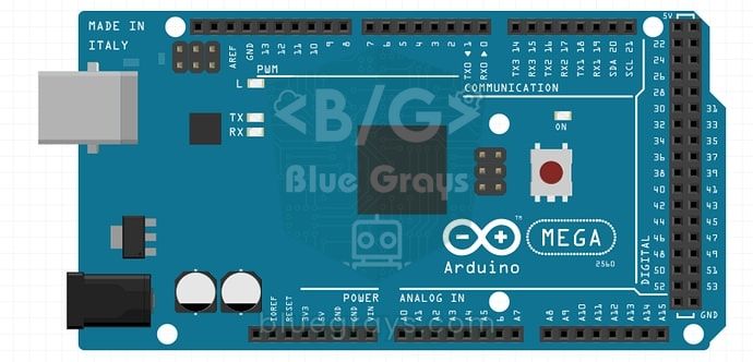
What is the Arduino Mega 2560 and how does it work?
The Arduino Mega 2560 is a development board built around the 8-bit ATmega2560 microcontroller. It runs at the same 16 MHz clock as the Uno, uses the same 5 V logic level and is programmed with the same Arduino IDE; in other words, the Mega isn't faster than the Uno, it's wider. Thanks to the 100-pin package, 70 signal pins can be brought out on the board. USB is handled by the ATmega16U2 chip on the board; clone boards usually use a CH340 for this job. You can power the board with 5 V over USB, or with 7–12 V through the barrel jack and Vin; the onboard regulator drops that voltage to 5 V. Program memory is 8 times the Uno's and RAM is 4 times, so big libraries, graphic displays and long menus run comfortably on the Mega. The left half of the board has the same pin layout as the Uno, so most Uno shields plug straight into the Mega.
| Feature | Value |
|---|---|
| Microcontroller | ATmega2560 (8-bit AVR) |
| Clock speed | 16 MHz |
| Flash memory | 256 KB (8 KB used by the bootloader) |
| SRAM | 8 KB |
| EEPROM | 4 KB |
| Operating voltage | 5 V |
| Input voltage (jack / Vin) | 7–12 V recommended, 6–20 V limit |
| Digital I/O | 54 (15 of them PWM) |
| Analog inputs | 16 (A0–A15, 10-bit) |
| Hardware serial ports | 4 (Serial, Serial1, Serial2, Serial3) |
| External interrupt pins | 6 |
| Current per pin | 20 mA recommended, 40 mA absolute maximum |
| 3.3V pin current | 50 mA maximum |
| Size | 101.5 × 53.3 mm |
Arduino Mega vs Uno comparison
| Feature | Arduino Uno R3 | Arduino Mega 2560 |
|---|---|---|
| Microcontroller | ATmega328P | ATmega2560 |
| Clock speed | 16 MHz | 16 MHz |
| Digital pins | 14 | 54 |
| PWM pins | 6 (3, 5, 6, 9, 10, 11) | 15 (2–13, 44, 45, 46) |
| Analog inputs | 6 (A0–A5) | 16 (A0–A15) |
| Hardware serial ports | 1 | 4 |
| External interrupt pins | 2 (2, 3) | 6 (2, 3, 18, 19, 20, 21) |
| Flash / SRAM / EEPROM | 32 KB / 2 KB / 1 KB | 256 KB / 8 KB / 4 KB |
| I2C pins | A4 (SDA), A5 (SCL) | 20 (SDA), 21 (SCL) |
| SPI pins | 10, 11, 12, 13 | 53, 51, 50, 52 |
| Size | 68.6 × 53.4 mm | 101.5 × 53.3 mm |
Arduino Mega pin map: all pin groups
| Pin group | Pin numbers | Function and notes |
|---|---|---|
| Digital pins shared with the Uno | 0–13 | 0 (RX0) and 1 (TX0) are the USB serial line; pin 13 has the onboard LED |
| Extra serial port pins | 14–19 | 14 TX3, 15 RX3, 16 TX2, 17 RX2, 18 TX1, 19 RX1 |
| I2C | 20 (SDA), 21 (SCL) | Wire library; the board has 10 kΩ pull-up resistors to 5 V |
| Double-row digital header | 22–53 | General-purpose input/output; no PWM except 44, 45 and 46 |
| PWM | 2–13, 44, 45, 46 | Used with analogWrite(pin, 0–255) |
| SPI | 50 (MISO), 51 (MOSI), 52 (SCK), 53 (SS) | The same signals are also on the ICSP header |
| Analog inputs | A0–A15 (digital 54–69) | Read with analogRead, can also be used as digital pins |
| Power and control | 5V, 3.3V, Vin, GND, IOREF, AREF, RESET | AREF is the external analog reference input; pulling RESET LOW restarts the board |
PWM pins and timers
The Mega has 15 PWM outputs: the 12 pins from 2 to 13, plus 44, 45 and 46. With these pins you can set LED brightness and motor speed using analogWrite(pin, 0–255). PWM signals come from six hardware timers (Timer0–Timer5); Timer0 and Timer2 are 8-bit, the others are 16-bit. Because Timer0 also drives millis() and delay(), pins 4 and 13 run at about 980 Hz and the remaining PWM pins at about 490 Hz. The key thing to watch is that when a library takes over a timer, PWM on the pins tied to that timer breaks: on the Mega the Servo library uses Timer5 for the first 12 servos, so the moment you attach a servo, analogWrite stops working on 44, 45 and 46; tone() uses Timer2 and affects pins 9 and 10. You'll find duty cycle and frequency explained in detail in What Is PWM?.
| Timer | PWM pins | Default frequency | What does it conflict with? |
|---|---|---|---|
| Timer0 (8-bit) | 4, 13 | ~980 Hz | millis() and delay() |
| Timer1 (16-bit) | 11, 12 | ~490 Hz | Servo library (servos 13–24) |
| Timer2 (8-bit) | 9, 10 | ~490 Hz | tone() function |
| Timer3 (16-bit) | 2, 3, 5 | ~490 Hz | Servo library (servos 25–36) |
| Timer4 (16-bit) | 6, 7, 8 | ~490 Hz | Servo library (servos 37–48) |
| Timer5 (16-bit) | 44, 45, 46 | ~490 Hz | Servo library (first 12 servos) |
4 hardware serial ports: Serial, Serial1, Serial2, Serial3
The Uno has a single hardware serial port, and it's shared with USB; for a second device you're forced to use SoftwareSerial. SoftwareSerial can drop data at high speeds, can listen to only one port at a time, and slows down the rest of your code because it disables interrupts while receiving bytes. The Mega has four independent UART peripherals; each works in the background with its own 64-byte receive buffer, so incoming data isn't lost while you're busy with other work in loop(). The wiring rule is the same for every port: the module's TX goes to the Mega's RX, the module's RX goes to the Mega's TX, and the grounds must always be common. When connecting the Mega's 5 V TX output to the RX input of a module that works at 3.3 V logic, bring the signal down to about 3.3 V with a 1 kΩ and 2 kΩ voltage divider. The bridge code below passes whatever you type in the Serial Monitor to Serial1 and whatever comes from Serial1 back to the Serial Monitor; it's the fastest way to test modules like the HC-05. For how UART works, see the UART serial communication post.
| Port | TX pin | RX pin | Typical use |
|---|---|---|---|
| Serial | 1 | 0 | USB and Serial Monitor |
| Serial1 | 18 | 19 | HC-05 Bluetooth module |
| Serial2 | 16 | 17 | NEO-6M GPS module |
| Serial3 | 14 | 15 | SIM800L GSM or fingerprint sensor |
1// USB Seri Monitör <-> Serial1 köprüsü / USB Serial Monitor <-> Serial1 bridge
2// Serial1: TX1 = 18, RX1 = 19
3
4void setup() {
5  Serial.begin(9600);    // bilgisayar (USB) / computer (USB)
6  Serial1.begin(9600);   // HC-05, GPS vb. / HC-05, GPS, etc.
7  Serial.println(F("Mega seri kopru hazir / serial bridge ready"));
8}
9
10void loop() {
11  if (Serial1.available()) {        // modülden gelen veri / data from the module
12    Serial.write(Serial1.read());
13  }
14  if (Serial.available()) {         // Seri Monitör'den gelen veri / data from the Serial Monitor
15    Serial1.write(Serial.read());
16  }
17}
Interrupt pins
An external interrupt lets you catch a change on a pin within microseconds, whatever loop() is doing at that moment; it's ideal for encoders, water flow sensors, tachometers and buttons that need a fast response. The Mega has 6 pins usable with attachInterrupt: 2, 3, 18, 19, 20 and 21. Interrupt numbers don't follow pin order (2 → 0, 3 → 1, 21 → 2, 20 → 3, 19 → 4, 18 → 5); so instead of typing the number by hand, always use digitalPinToInterrupt(pin). Watch out: 18 and 19 are Serial1's pins and 20 and 21 are the I2C pins; if you use Serial1 and I2C, only 2 and 3 are left. If you need more pins, the ATmega2560's pin change interrupts (PCINT) work on pins 10–15, 50–53 and A8–A15 and can be used with suitable libraries. The code below counts pulses on pins 2 and 18; the interrupt functions are kept short, the shared counters are declared volatile, and interrupts are paused briefly while reading. Since 18 is used for the interrupt in this example, Serial1 can't be used. To go deeper, read the Arduino interrupt post.
1// Arduino Mega: 2 ve 18 numaralı pinlerde darbe sayma / pulse counting on pins 2 and 18
2volatile unsigned long countA = 0;   // pin 2
3volatile unsigned long countB = 0;   // pin 18
4
5void onPulseA() { countA++; }        // kısa tut / keep it short
6void onPulseB() { countB++; }
7
8void setup() {
9  Serial.begin(115200);
10  pinMode(2, INPUT_PULLUP);          // buton ya da sensör GND'ye çeker / button or sensor pulls to GND
11  pinMode(18, INPUT_PULLUP);
12  attachInterrupt(digitalPinToInterrupt(2), onPulseA, FALLING);
13  attachInterrupt(digitalPinToInterrupt(18), onPulseB, FALLING);
14}
15
16void loop() {
17  noInterrupts();                    // okurken kesmeleri durdur / pause interrupts while reading
18  unsigned long a = countA;
19  unsigned long b = countB;
20  interrupts();
21
22  Serial.print(F("Pin 2: "));
23  Serial.print(a);
24  Serial.print(F("  Pin 18: "));
25  Serial.println(b);
26  delay(500);
27}
16 analog inputs (A0–A15)
The Mega's 16 analog inputs share a single 10-bit ADC through a multiplexer. Each reading returns a value between 0 and 1023; with a 5 V reference, one step is about 4.9 mV. A conversion takes about 100 microseconds, so you can take around 10,000 readings per second, which means scanning 16 channels in turn is no problem at all. If you need more precise measurements, you can use analogReference to select the internal 1.1 V (INTERNAL1V1) or 2.56 V (INTERNAL2V56) reference; the Uno's INTERNAL option doesn't exist on the Mega. Analog pins can also be used as digital pins: A0 is digital pin 54 and A15 is digital pin 69, so you can light an LED on that pin by writing pinMode(A8, OUTPUT). When switching quickly between channels, the voltage of the previous channel can leak into the next measurement; for sources with an internal resistance above 10 kΩ, reading each channel twice and discarding the first value reduces this error. You can find how the ADC works in the analog to digital conversion post.
1// 16 analog kanalı sırayla oku / read all 16 analog channels in turn
2void setup() {
3  Serial.begin(115200);
4}
5
6void loop() {
7  for (byte ch = 0; ch < 16; ch++) {
8    int raw = analogRead(A0 + ch);          // A0..A15 = 54..69
9    float volts = raw * (5.0 / 1023.0);     // ham değeri volta çevir / convert raw value to volts
10    Serial.print(F("A"));
11    Serial.print(ch);
12    Serial.print(F("="));
13    Serial.print(volts, 2);
14    if (ch < 15) {
15      Serial.print(F("  "));
16    }
17  }
18  Serial.println();                         // satır sonu / end of line
19  delay(1000);
20}
I2C and SPI pins: compatibility with Uno shields
The difference people moving to the Mega trip over most is the location of the communication pins. On the Uno, I2C is on A4 and A5 and SPI is on pins 10–13, while on the Mega I2C is on 20 (SDA) and 21 (SCL) and SPI is on pins 50–53. On R3 boards, SDA and SCL are repeated on the header next to AREF; the SPI signals are in the same place on the 6-pin ICSP header in the middle of both boards. That's why shields that take SPI from the ICSP header work fine on the Mega, while older shields that take SPI directly from 11–13 don't. The Wire and SPI libraries use the right pins on their own; your job is to plug the wires into the right places. For SPI you can connect a device's CS pin to any digital pin you like, but never make pin 53 an input: if this pin becomes an input and is pulled LOW, the processor switches to slave mode on SPI and communication stops. For example, you'd connect an RC522 RFID reader as SDA → 53, SCK → 52, MOSI → 51, MISO → 50. For details of the protocols, see What is I2C? and What is SPI?.
| Signal | Arduino Uno | Arduino Mega | ESP32 | Raspberry Pi Pico |
|---|---|---|---|---|
| I2C SDA | A4 | 20 | GPIO 21 | GP4 |
| I2C SCL | A5 | 21 | GPIO 22 | GP5 |
| SPI MISO | 12 | 50 | GPIO 19 | GP16 |
| SPI MOSI | 11 | 51 | GPIO 23 | GP19 |
| SPI SCK | 13 | 52 | GPIO 18 | GP18 |
| SPI SS / CS | 10 | 53 | GPIO 5 | GP17 |
| Extra serial port TX / RX | None (SoftwareSerial) | 18 / 19 (Serial1) | GPIO 17 / 16 (Serial2) | GP0 / GP1 (UART0) |
| Logic level | 5 V | 5 V | 3.3 V | 3.3 V |
Step by step: your first Mega program (16-LED chaser)
- Connect the Mega to your computer with a USB-B cable; if your clone board's USB chip is a CH340, install its driver first.
- In the Arduino IDE, choose Arduino Mega or Mega 2560 from the Tools > Board menu and leave the Processor as ATmega2560 (Mega 2560).
- Select the board's port from the Tools > Port menu (something like COM3 on Windows, a name starting with /dev/cu.usbmodem or /dev/cu.wchusbserial on macOS).
- Connect 16 LEDs to pins 22–37, each through a 220 Ω resistor, and take the LEDs' short legs (cathodes) to the GND rail. A red LED draws (5 − 2) / 220 ≈ 13.6 mA; for other colours you can use the LED resistor calculator.
- Upload the code below; the LEDs will chase one after another. Since only one LED is on at a time, the total current stays under 20 mA. You can find the back-and-forth effect in the Knight Rider and chaser LED post.
1// Arduino Mega: 22-37 pinlerinde 16 LED'li yürüyen ışık / 16-LED chaser on pins 22-37
2const byte FIRST_PIN = 22;   // ilk LED pini / first LED pin
3const byte LED_COUNT = 16;   // 22..37
4
5void setup() {
6  for (byte i = 0; i < LED_COUNT; i++) {
7    pinMode(FIRST_PIN + i, OUTPUT);   // tüm LED pinleri çıkış / all LED pins as outputs
8  }
9}
10
11void loop() {
12  for (byte i = 0; i < LED_COUNT; i++) {
13    digitalWrite(FIRST_PIN + i, HIGH);  // LED'i yak / turn LED on
14    delay(60);
15    digitalWrite(FIRST_PIN + i, LOW);   // LED'i söndür / turn LED off
16  }
17}
When do you need an Arduino Mega?
- If you're running out of pins: a 4x4 keypad alone needs 8 pins and a parallel LCD needs 6; add relays, buttons and sensors on top and the Uno's 20 pins run out fast.
- If you have several serial devices: listening to a GPS, Bluetooth and GSM at the same time is nearly impossible on the Uno, while on the Mega each gets its own hardware port.
- If memory is running out: if the compiler warns about low memory, or you're combining a TFT display, SD card and menu code, 256 KB of flash and 8 KB of RAM give you a lot of breathing room; details in the Arduino out of memory post.
- If you have many analog sensors: with 16 channels you can read soil moisture, gas, light and potentiometers without needing a multiplexer.
- For robots with many servos: the Servo library supports up to 48 servos on the Mega (12 on the Uno); it's suitable for a robot arm and walking robots.
- When you don't need a Mega: if you need Wi-Fi, high speed or low power, the ESP32 makes more sense (Arduino or ESP32?); if you're only a few outputs short, expanding the Uno's pins with a 74HC595 shift register is a cheaper and smaller solution.
Arduino Mega and RAMPS 1.4 in 3D printers
For years, most DIY 3D printers and small CNC machines ran on an Arduino Mega with a RAMPS 1.4 board plugged on top; this pair is still the most common educational printer electronics today. The reason is simple: printer firmware like Marlin easily exceeds 100 KB with display and SD card support; five stepper drivers (X, Y, Z and two extruders), three MOSFET outputs, six limit switches, thermistors, an LCD and an SD card also need dozens of pins. On RAMPS, the X axis step and direction signals are connected to 54 and 55 (A0 and A1), the Y axis signals to 60 and 61 (A6 and A7), the Z axis signals to 46 and 48, and the first extruder's signals to 26 and 28. The nozzle heater is driven from PWM pin 10, the bed heater from 8 and the fan from 9; the nozzle and bed thermistors are read from A13 and A14. This layout is also a nice example of how analog pins can be put to efficient use as digital outputs. For current setting and microstepping of the stepper drivers, take a look at the A4988 stepper motor driver post.
Multi-sensor project example: planning pins properly
| Module | Mega pin | Why this pin? |
|---|---|---|
| HC-05 Bluetooth | 18 (TX1), 19 (RX1) | Communication with the phone runs on a hardware serial port, so no data is lost |
| NEO-6M GPS | 16 (TX2), 17 (RX2) | A GPS sends many lines every second and needs its own port |
| SIM800L GSM | 14 (TX3), 15 (RX3) | The third independent port for SMS and calls |
| I2C LCD + BME280 | 20 (SDA), 21 (SCL) | Two devices share the same I2C line with different addresses |
| RC522 RFID | 50, 51, 52, 53 + RST 49 | Hardware SPI bus, with 53 used as CS |
| Soil moisture sensors (4) | A0–A3 | The first four of the 16 analog channels |
| MQ-2 gas sensor | A4 | Sensor with an analog output |
| Water flow sensor | 2 | External interrupt pin so no pulses are missed |
| 8-channel relay module | 22–29 | Plain digital outputs that don't need PWM |
| Fan (via MOSFET) | 6 | PWM for speed control (Timer4) |
| Servo (hatch) | 8 | A servo signal can come from any digital pin; because Timer5 is used, 44–46 can't be used for PWM |
Common mistakes and how to fix them
| Symptom | Cause | Fix |
|---|---|---|
| Code won't upload, avrdude timeout error | The board is still set to Uno, the port is wrong, or a module is connected to pins 0 and 1 | Select Mega 2560 and the correct port from the Tools menu, and unplug the wires on 0 and 1 during upload |
| I2C display or sensor not found | Wires were plugged into A4 and A5 out of Uno habit | Connect SDA to 20 and SCL to 21 |
| SPI module on a shield doesn't work | The shield takes its SPI signals from pins 11–13 | Use the ICSP header or pins 50–52 |
| analogWrite stopped on 44–46 after adding a servo | The Servo library uses Timer5 | Move the PWM output to a pin between 2 and 13 |
| SoftwareSerial receives no data | The chosen RX pin doesn't support pin change interrupts | Use the Serial1, Serial2 or Serial3 hardware ports |
| Board gets hot or resets by itself | A motor, relay coil or many LEDs are driven directly from the pins | Use a transistor, MOSFET or motor driver and add an external supply |
| Analog values keep fluctuating | Reading a floating input or leakage between channels | Read only the channels with a sensor connected, and read each channel twice and average |
The Arduino Mega is the easiest step up for anyone who knows the Uno: the same code, the same libraries, but far more pins, ports and memory. The Arduino Uno pinout and Arduino Nano pinout guides will also come in handy for smaller projects. In the BlueGrays app you can go step by step through pin-hungry projects such as a 4-digit 7-segment digital clock, a keypad and LCD combination lock, an obstacle-avoiding robot and a smart electronics safe, with circuit diagrams and code, and adapt the pin layout to your own Mega.
Frequently asked questions
How many pins does the Arduino Mega have?
The Arduino Mega 2560 has 70 signal pins in total: 54 digital I/O and 16 analog inputs. 15 of the digital pins give PWM output, and the analog pins (A0–A15) can also be used as digital pins 54–69 when needed. In addition there are power and control pins such as 5V, 3.3V, Vin, GND, AREF, IOREF and RESET.
Which are the Arduino Mega PWM pins?
On the Mega, pins 2 to 13 and pins 44, 45 and 46 give PWM, for a total of 15 PWM outputs. Pins 4 and 13 run at about 980 Hz and the others at about 490 Hz. When the Servo library is used, PWM on 44, 45 and 46 is disabled.
Where are the Arduino Mega SDA and SCL pins?
On the Mega, the I2C bus is on pins 20 (SDA) and 21 (SCL); on R3 boards the same signals are also on the header next to AREF. A4 and A5 on the Mega are ordinary analog inputs, not I2C as on the Uno. SPI is on pins 50 (MISO), 51 (MOSI), 52 (SCK) and 53 (SS) and on the ICSP header.
Does Arduino Uno code work on the Mega?
Most Uno code compiles and runs on the Mega without any changes; you only need to select Mega 2560 as the board in the Tools menu. Problems usually show up on the hardware side: the I2C and SPI pins are in different places, and code that accesses timer and port registers directly needs to be rearranged. Moving code that uses SoftwareSerial to the Mega's hardware serial ports also gives more reliable results.
Which are the Arduino Mega interrupt pins?
The external interrupt pins usable with attachInterrupt are 2, 3, 18, 19, 20 and 21. Since 18 and 19 are shared with Serial1 and 20 and 21 with I2C, only 2 and 3 are left free if you use those buses. Using digitalPinToInterrupt(pin) instead of typing the interrupt number by hand prevents mistakes.
Can I connect a 3.3 V sensor to the Arduino Mega?
Yes, but it needs care. The Mega works with 5 V logic; it usually reads a 3.3 V output as HIGH, but the Mega's 5 V output can damage a 3.3 V input. So use a voltage divider or a logic level converter on the module's input pins; for I2C, prefer a bidirectional level converter because of the 5 V pull-up resistors on the board.
Projects to build after reading this
See all projects
LED Chaser
Lights that switch on one after another, as if they were running. The Arduino lights six LEDs one at a time; each glows for a brief moment and goes out, so the light walks from start to end and then…

Knight Rider LED Effect
The classic scanner light: a dot of light slides from one end of six LEDs to the other and then comes back.
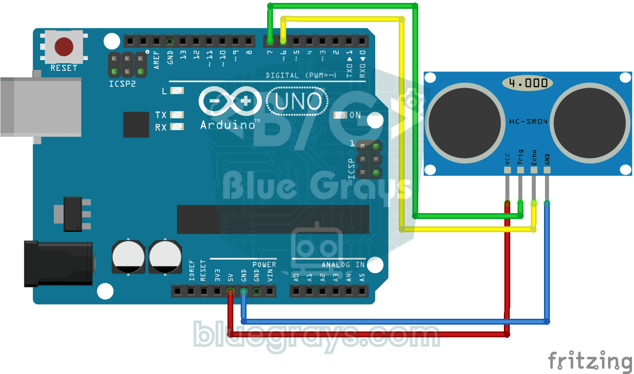
HC-SR04 Distance Measurement (Serial Display)
The HC-SR04 sensor works just like a bat finding its way in the dark: it sends out a sound you cannot hear, listens for the echo and measures how far away the object in front of it is.
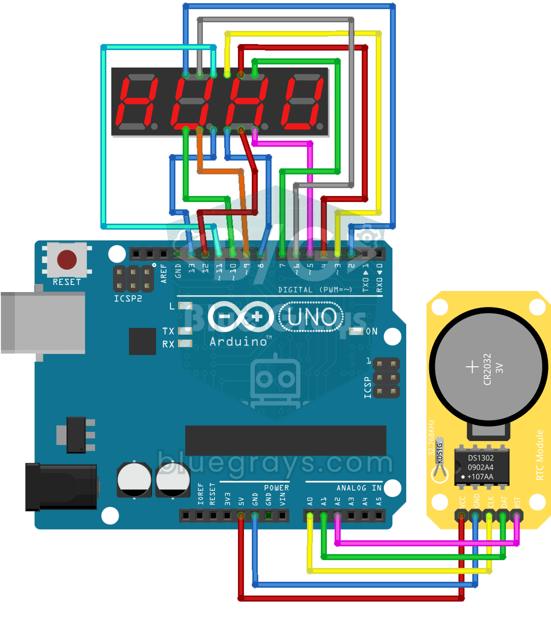
Digital Clock with 4-Digit 7-Segment Display
A four-digit glowing digital clock, much like the one on a kitchen oven. The DS1302 clock module keeps the time, and every second the Arduino reads the hours and minutes and shows them on the…
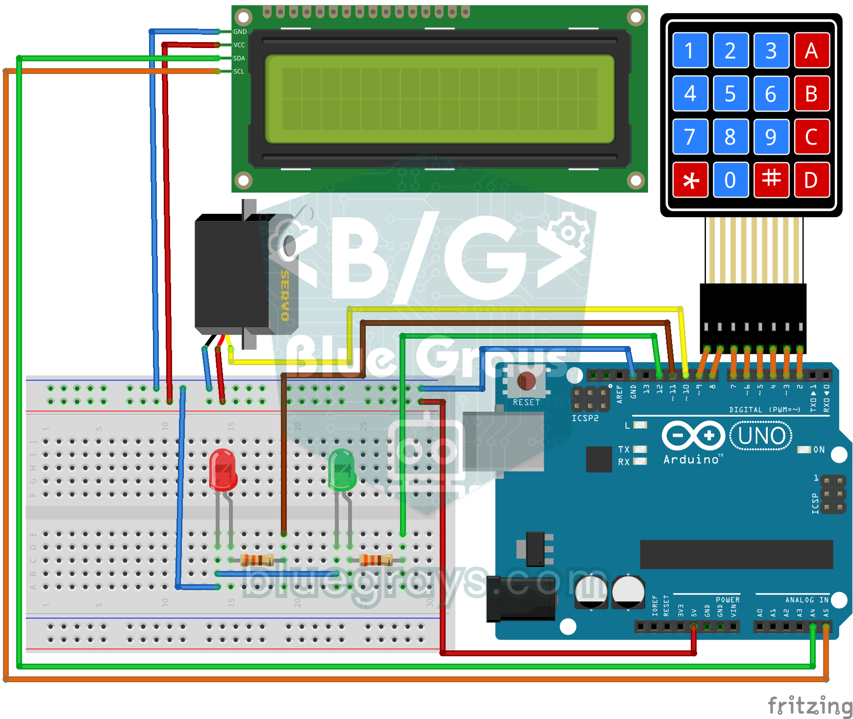
Password Lock with 4x4 Keypad and LCD
A small electronic door lock that keeps out anyone who doesn't know the code. You press the hash key and type the code on the keypad; if it is right, the screen says access granted, the green LED…

Obstacle Avoidance Robot
How about building a smart vehicle that finds its own way? The Obstacle Avoidance Robot constantly scans its surroundings thanks to the ultrasonic sensor in front of it.

Smart Electronic Safe
A small safe for your valuables that opens with a code. You type your four-digit code on the keypad; if it is right, the servo motor opens the lock, the green light comes on and the screen shows the…

Servo Circle Choreography - Animated Patterns with 32 Servos
A visual animation project driven by 32 servo motors arranged in a circle on an Arduino Mega. The servos are managed in a single array, connected to the Mega's pins 22–53, and perform four motion sequences: a chaotic jitter at random angles, a synchronized sweep, a wave travelling around the circle and a compass needle swinging left and right.