
ESP32 Blue LED Meaning: Arduino L, TX/RX and Pico Onboard LEDs
ESP32 blue LED meaning, plus the red power LED, Arduino ON, L, TX and RX and the Pico GP25 LED: a board-by-board table, blinking causes and LED_BUILTIN.
The ESP32 blue LED is, on most ESP32 DevKit V1 boards, a user LED wired to GPIO 2 and controlled entirely by your code; the red LED next to it only means the board is powered. The ON, L, TX and RX lights on an Arduino Uno and the little green LED on a Raspberry Pi Pico work the same way: each one reports either a hardware state or what your program is doing. Once you can read them, you can tell at a glance whether a board has power, whether data is flowing during an upload and whether your sketch is actually running.
In this guide we've put together a table of which pin or rail every LED on Arduino, ESP32 and Pico boards is connected to. We'll explain the real reasons behind common situations like "the ESP32 blue LED stays on", "the blue LED keeps flashing" and "the Arduino L LED blinks by itself", show which pin LED_BUILTIN points to on each board, and use code to turn the onboard LED into a status indicator for your own projects.
What are the onboard LEDs for?
The LEDs on development boards fall into three groups. Power LEDs are connected straight to a supply rail through a resistor; they stay on as long as the board has power and can't be switched off in software. Communication LEDs (TX and RX) are driven by the USB-to-serial chip and flash whenever data is exchanged with the computer. User LEDs are wired to a microcontroller pin and do only what your code tells them; the Arduino's L, the ESP32's blue LED and the Pico's green LED belong to this group. The table below summarises the most common boards:
| Board | LED | Connected to | Meaning |
|---|---|---|---|
| Arduino Uno R3 | ON (green) | 5 V rail | Board is powered |
| Arduino Uno R3 | L (yellow/orange) | D13 (through an op-amp buffer) | LED controlled by your code; the bootloader also flashes it after a reset |
| Arduino Uno R3 | TX / RX (yellow) | USB-to-serial chip (ATmega16U2) | Data exchange with the computer; flashes rapidly during uploads |
| Arduino Nano / Mega | POW or ON, L, TX, RX | 5 V, D13, USB-to-serial chip | Same meaning as on the Uno |
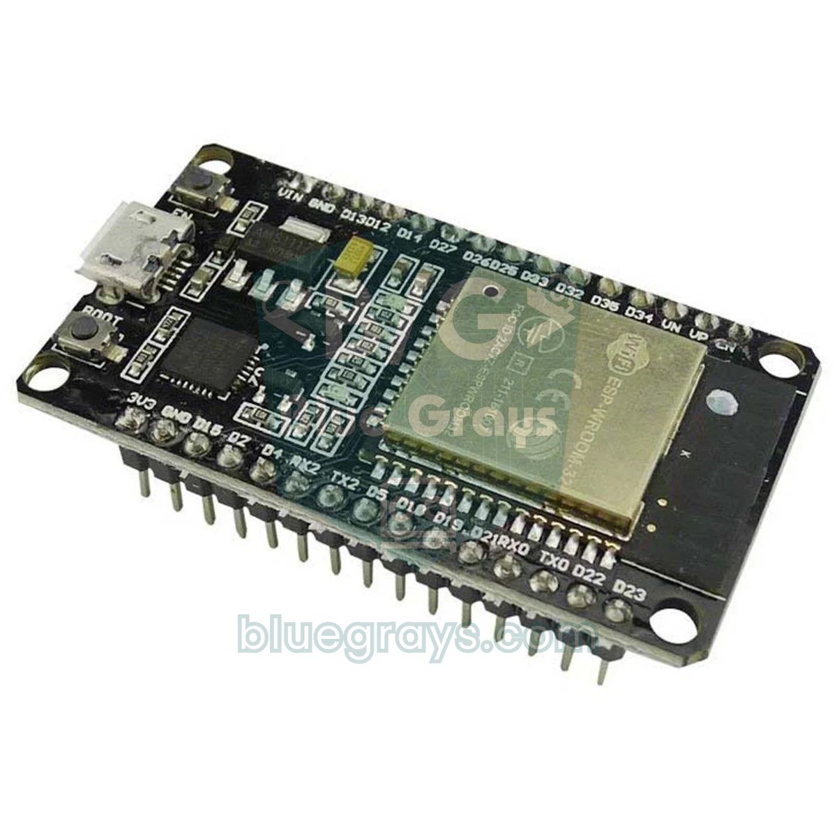
| ESP32 DevKit V1 | Red LED | 3.3 V rail | Board is powered; can't be turned off in code |
| ESP32 DevKit V1 | Blue LED | GPIO 2 | LED controlled by your code |
| ESP32-DevKitC (Espressif) | Red LED | 3.3 V rail | Power only; no user LED |
| ESP32-S3-DevKitC | RGB LED (WS2812) | GPIO 48 (38 on some revisions) | Set any colour from code |
| ESP32-CAM | Red LED / white flash | GPIO 33 / GPIO 4 | Status LED (lights on LOW) / camera flash |
| Wemos D1 mini, NodeMCU | Blue LED | GPIO 2 (D4) | User LED; lights on LOW |
| Raspberry Pi Pico | Green LED | GP25 | LED controlled by your code; no power LED |
| Raspberry Pi Pico W | Green LED | Wi-Fi chip (WL_GPIO0) | Controlled with Pin("LED") |
The Arduino Uno LEDs: ON, L, TX and RX
The ON LED is connected to the 5 V rail and lights up as soon as the board gets power from USB or the barrel jack. If it stays dark, the board has no power: the cable may be faulty, the USB port may not be supplying power, or a short circuit in your wiring has tripped the board's self-resetting fuse (polyfuse). The L LED is connected to digital pin 13; on the Uno R3 an op-amp buffer sits in between, so the LED doesn't load the pin itself. The TX and RX LEDs are driven by the ATmega16U2 USB-to-serial chip: TX flashes while you upload code or send data to the computer with Serial.print(), and RX flashes when data comes in from the computer. One important detail: on the Uno R3 these two LEDs only show USB traffic, so they don't flash when you talk to a Bluetooth module wired to pins 0 and 1.
Why does the Arduino L LED blink on its own?
- The factory Blink sketch: Most new Uno and Nano boards ship with the Blink example loaded for testing, so L blinks once a second. It stops as soon as you upload your own code.
- The bootloader's start-up flashes: When you press reset, plug in USB or open the Serial Monitor, the board restarts and the bootloader flashes L a few times quickly before your code runs.
- L glowing dimly or staying on: If your code doesn't use D13, the pin floats as an input, and because the input of the Uno R3's op-amp buffer is left floating too, L can glow faintly or fully. It's not a fault.
- Flickering with an SPI module attached: D13 is the SPI clock (SCK) line. L flickers while an RFID RC522, SD card or Ethernet module is working, which is also normal.
- Constant fast blinking and your code doesn't run: The board keeps resetting. A weak power supply, a short between 5 V and GND or code that causes a reset loop can all do this.
1// Uno, Nano, Mega: L LED'i D13'tedir, LED_BUILTIN = 13 / the L LED is on D13, LED_BUILTIN = 13
2void setup() {
3  pinMode(LED_BUILTIN, OUTPUT);
4}
5
6void loop() {
7  digitalWrite(LED_BUILTIN, HIGH);   // L yanar / L on
8  delay(1000);
9  digitalWrite(LED_BUILTIN, LOW);    // L söner / L off
10  delay(1000);
11}What do the red and blue LEDs on the ESP32 mean?
The red LED on the ESP32 DevKit V1 and similar boards is connected to the 3.3 V rail coming out of the regulator. It lights up when the board is powered from USB or the VIN pin and can't be turned off by any code. If it doesn't light at all, the board has no power; if it flickers or glows dimly, the supply is too weak. The blue LED is a user LED on GPIO 2: it lights when the pin is HIGH and goes off when it's LOW. Not every ESP32 board has one; Espressif's own ESP32-DevKitC has only a power LED, and ESP32-S3 and ESP32-C3 boards usually carry an addressable RGB LED instead of a single-colour one.
For most people asking why the ESP32 blue LED stays on, the reason is simple: the sketch on the board has set GPIO 2 HIGH and left it there, or a circuit connected to GPIO 2 is pulling the pin up. On new boards, a blue LED that blinks by itself usually comes from a Blink-style test program the seller loaded. If your code doesn't touch the LED and it still flashes fast and irregularly, the board is most likely restarting over and over: open the Serial Monitor at 115200 baud and look for a message like "Brownout detector was triggered" or "Guru Meditation Error". If the blue LED never lights, your board may have no user LED, or your code is driving a different pin.
Turning the ESP32 blue LED into a Wi-Fi status indicator
The most useful job for an onboard LED is telling you what state a device without a screen is in. The code below flashes the blue LED five times a second while the ESP32 is trying to join Wi-Fi, and gives a short "heartbeat" every two seconds once it's connected. Even with the device mounted on a wall, you can see from across the room whether it's on the network and whether the program has frozen. Because the code doesn't use delay(), you can still add other work to loop():
1#include <WiFi.h>
2
3const char* ssid = "AgAdi";          // Wi-Fi adın / your Wi-Fi name
4const char* password = "Sifre123";   // Wi-Fi şifren / your Wi-Fi password
5const int LED_PIN = 2;               // DevKit V1 mavi LED / blue LED on DevKit V1
6
7void setup() {
8  pinMode(LED_PIN, OUTPUT);
9  WiFi.mode(WIFI_STA);
10  WiFi.begin(ssid, password);
11}
12
13void loop() {
14  unsigned long t = millis();
15  if (WiFi.status() == WL_CONNECTED) {
16    digitalWrite(LED_PIN, (t % 2000) < 80);   // bağlı: 2 sn'de bir kısa çakma / connected: short flash every 2 s
17  } else {
18    digitalWrite(LED_PIN, (t % 200) < 100);   // bağlanıyor: hızlı yanıp sönme / connecting: fast blink
19  }
20}
The trick here is millis() % period: millis() returns the milliseconds since start-up, and the modulo turns that number into a counter that cycles between 0 and the period. The LED is on while the counter is below a set value and off above it; when connected, for example, the LED is lit only for the first 80 ms of each 2000 ms period. We explain the difference between delay() and millis() in detail in Arduino millis() vs delay(); if the board never connects, work through the checklist in ESP32 Not Connecting to Wi-Fi.
The RGB LED on ESP32-S3 and ESP32-C3 boards
On newer Espressif boards the user LED is usually an addressable WS2812-type RGB LED. On the ESP32-S3-DevKitC it's connected to GPIO 48 (GPIO 38 on some revisions of the board), and on the ESP32-C3-DevKitM to GPIO 8. You can't set its colour with digitalWrite(), because it takes colour data as a precisely timed bit stream. The ESP32 Arduino core provides a ready-made function for this: rgbLedWrite() in the 3.x versions and neopixelWrite() in 2.x. The code below compiles on both and cycles the LED through red, green and blue. Cheap ESP32-C3 SuperMini boards, on the other hand, have a single blue LED on GPIO 8 that lights on LOW instead of an RGB LED.
1// ESP32-S3-DevKitC dahili RGB LED (WS2812): GPIO 48, bazı sürümlerde 38 / onboard RGB LED: GPIO 48 (38 on some revisions)
2const uint8_t RGB_PIN = 48;
3
4void setColor(uint8_t r, uint8_t g, uint8_t b) {
5#if ESP_ARDUINO_VERSION_MAJOR >= 3
6  rgbLedWrite(RGB_PIN, r, g, b);      // ESP32 çekirdeği 3.x / ESP32 core 3.x
7#else
8  neopixelWrite(RGB_PIN, r, g, b);    // ESP32 çekirdeği 2.x / ESP32 core 2.x
9#endif
10}
11
12void setup() {
13}
14
15void loop() {
16  setColor(40, 0, 0);  delay(500);    // kırmızı / red
17  setColor(0, 40, 0);  delay(500);    // yeşil / green
18  setColor(0, 0, 40);  delay(500);    // mavi / blue
19  setColor(0, 0, 0);   delay(500);    // kapalı / off
20}
The onboard LED on the Raspberry Pi Pico and Pico W
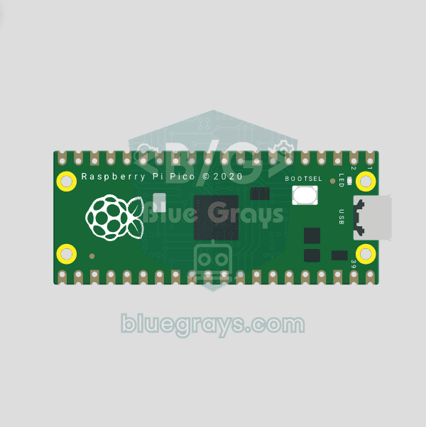
The Raspberry Pi Pico has a single green LED next to the USB socket, connected to pin GP25. The Pico has no power LED, so with no program running it looks completely dead even when plugged into USB, and first-time users often think the board is broken. On the Pico W and Pico 2 W, the LED isn't connected to the microcontroller at all but to a pin on the Wi-Fi chip, and GP25 is used to talk to the wireless chip. That's why Pin(25) won't light the LED on a Pico W; in MicroPython you have to write Pin("LED"). Recent MicroPython versions accept this on the plain Pico too, so you can write one piece of code for both boards:
1from machine import Pin, Timer
2
3led = Pin("LED", Pin.OUT)    # Pico, Pico W, Pico 2 ve Pico 2 W'de çalışır / works on all Pico boards
4# Çok eski Pico yazılımında / on very old Pico firmware: led = Pin(25, Pin.OUT)
5
6timer = Timer()
7timer.init(freq=2, mode=Timer.PERIODIC, callback=lambda t: led.toggle())   # saniyede bir yanıp sönme / one blink per second
Always flash the MicroPython build made for the Pico W onto a Pico W; the plain Pico firmware doesn't know about the Wi-Fi chip, so it can't reach the LED either. If you program the Pico from the Arduino IDE (with Earle Philhower's Raspberry Pi Pico/RP2040 core), LED_BUILTIN points to the right LED on both boards. A Pico plugged in while holding BOOTSEL lights no LED at all; if it shows up on your computer as a drive called RPI-RP2, the board is fine. To get to know the board, see What Is the Raspberry Pi Pico?.
What is LED_BUILTIN, and which pin is it on each board?
LED_BUILTIN is a constant written in the board definition file that holds the pin number of that board's user LED. If you use LED_BUILTIN in your code instead of 13 or 2, the same sketch lights the right LED on different boards. Watch out for two things: the board selected in the Arduino IDE must match the one in your hand, and some generic board definitions don't have the constant at all. On the ESP32, for example, with ESP32 Dev Module selected the compiler may complain "'LED_BUILTIN' was not declared in this scope"; in that case pick the DOIT ESP32 DEVKIT V1 board or add const int LED_PIN = 2; at the top of your code.
| Board | LED_BUILTIN | Note |
|---|---|---|
| Arduino Uno, Nano, Mega, Leonardo, Uno R4 | 13 | HIGH turns it on |
| Wemos D1 mini, NodeMCU (ESP8266) | 2 | LOW turns it on (inverted) |
| ESP32 (with DOIT ESP32 DEVKIT V1 selected) | 2 | HIGH turns it on |
| ESP32 Dev Module | May not be defined | Define it yourself: const int LED_PIN = 2; |
| ESP32-S3-DevKitC | RGB_BUILTIN (GPIO 48) | Use rgbLedWrite() or neopixelWrite() for colour |
| Raspberry Pi Pico (Arduino core) | 25 | HIGH turns it on |
| Raspberry Pi Pico W (Arduino core) | Special virtual pin | Just write LED_BUILTIN |
What is each LED telling you? Symptom table
| Symptom | Likely meaning | What to do |
|---|---|---|
| Arduino L blinks once a second | The factory Blink sketch is loaded | Normal; stops when you upload your own code |
| L flashes quickly a few times after reset | The bootloader is starting, then your code runs | Normal |
| L flashes fast non-stop, code doesn't run | The board keeps resetting | Check the power supply and for shorts, re-upload the code |
| L glows dimly or stays on by itself | D13 is floating, the op-amp input is open | Normal; set D13 to OUTPUT and LOW if you like |
| ON LED doesn't light | No power, faulty cable or tripped fuse | Try another cable and port, remove the short, wait a few minutes |
| TX/RX never flash during upload | Wrong port, driver or board selection | Select the right port and board, install the CH340 driver |
| ESP32 blue LED stays on | The sketch left GPIO 2 HIGH | Check GPIO 2 in your code |
| ESP32 blue LED flashes fast and irregularly | The board keeps restarting, or a test program is loaded | Check the Serial Monitor for errors, improve the power supply |
| ESP32 blue LED never lights | No user LED on the board, or the code drives another pin | Check the pin number or connect an external LED |
| ESP32 red LED flickers | Not enough power (voltage dips when Wi-Fi transmits) | Use a good cable and a 5 V adapter rated for at least 1 A |
| No LED lights on the Pico | The Pico has no power LED and no program is running | Normal; check whether the RPI-RP2 drive appears with BOOTSEL |
Using the onboard LED in your projects
- Error codes: Flash the LED twice if a sensor isn't found and three times if there's no Wi-Fi, then pause; you'll know what's wrong without opening the Serial Monitor.
- Heartbeat: Give a short flash every few seconds while the program is healthy; if the LED stops, you know the code is stuck somewhere.
- Event notification: Flash the LED once when an MQTT message or web request arrives; it makes debugging ESP32 web servers much easier.
- Breathing effect: Fade the onboard LED in and out with PWM on the ESP32 and Pico; on the Uno this doesn't work because D13 has no PWM. Details in What Is PWM?.
- Battery projects: On a device that uses deep sleep, always switch the onboard LED off before sleeping; ESP32 Deep Sleep shows how to bring the current down to the µA range.
- Moving to an external LED: For a brighter or different-coloured indicator, add an LED and resistor as shown in What Is an LED?.
Onboard LEDs are the first and cheapest debugging tool in electronics: they answer "is there power?", "is data flowing?" and "is the program running?" in seconds. If you want to take the first step, the Arduino LED Blink, ESP32 Onboard LED and Raspberry Pi Pico Onboard LED projects in the BlueGrays app walk you through the wiring diagrams and code.
Frequently asked questions
What does the blue LED on the ESP32 mean?
On the ESP32 DevKit V1 and similar boards, the blue LED is a user LED connected to GPIO 2, and only the code you upload turns it on or off. The red LED is the one that shows the board is powered. Not every ESP32 board has a blue LED; Espressif's DevKitC only has a power LED.
Why is the blue LED on my ESP32 always on?
The most common reason is a sketch on the board that sets GPIO 2 HIGH. A module connected to GPIO 2 can also pull the pin up and light the LED. Set GPIO 2 LOW in your code or move the circuit to another pin; a lit blue LED on its own isn't a fault.
Why is my ESP32 blue light flashing?
If your sketch doesn't blink GPIO 2, a fast, irregular flash usually means the board is stuck in a restart loop, often because of a weak power supply or a crash. Open the Serial Monitor at 115200 baud and look for brownout or Guru Meditation messages. A steady blink on a brand-new board is usually the seller's test program.
Which pin is LED_BUILTIN on the ESP32?
In the DOIT ESP32 DEVKIT V1 board definition, LED_BUILTIN is GPIO 2. With ESP32 Dev Module selected the constant may not exist and the compiler throws an error; writing const int LED_PIN = 2; in your code fixes it. On ESP32-S3 boards, RGB_BUILTIN is used for the RGB LED.
Why doesn't the onboard LED work on my Raspberry Pi Pico W?
On the Pico W the LED is wired to the Wi-Fi chip rather than the microcontroller, so it can't be controlled with Pin(25). In MicroPython, write Pin("LED", Pin.OUT) and make sure you've flashed the MicroPython firmware built for the Pico W.
Why does the Arduino L LED blink by itself?
New boards usually ship with the Blink sketch preloaded, so L blinks once a second. A few quick flashes after a reset come from the bootloader. If D13 isn't used, L can glow dimly, and with an SPI module attached it can flicker; all of this is normal.
Projects to build after reading this
See all projects
ESP32 Built-in LED Blink
Blinking the built-in blue LED on the ESP32 DevKit V1. No external components required! The first project you should try when you buy an ESP32. GPIO 2 is connected to the built-in LED.
Raspberry Pi Pico Onboard LED Blink (Pico and Pico W)
The opening project of the Raspberry Pi Pico series! We blink the Pico's green built-in LED to confirm the board works, the classic "Hello World" first experiment. No external parts needed, just the Pico and a USB cable. The code is written in MicroPython, the language officially supported by the Raspberry Pi Foundation.

LED Blink
The very first hello of electronics: switching a single LED on and off. The Arduino turns the LED on and off at short intervals, so the light blinks quickly.

LED Blink with ESP32
Teaches basic GPIO output usage with ESP32. We achieve a blinking effect by turning an LED on and off from a digital pin. ESP32 version of the classic blink project on Arduino UNO; the basic blink commands in the Arduino environment are the same, but the ESP32's pin layout and 3.3 V GPIO levels differ from those of the Arduino UNO.
Raspberry Pi Pico: Controlling an External LED (Breadboard)
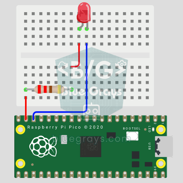
The next step after the Pico's built-in LED: connect an external LED on a breadboard and control it through pin GP14. You'll learn how to use any of the Pico's GPIO pins as an output, the LED's polarity (long leg = anode/+, short leg = cathode/–) and why a current-limiting resistor (220Ω) is a must. Without the resistor, too much current flows through the LED and it can burn out.

LED Control with a Push Button (Push)
Just like a doorbell: the light stays on as long as you press, and goes off when you let go.

ESP32 LED Control with Push Button (Push)
The LED lights up when the button is pressed and turns off when released. Shows how the ESP32's digital input pin and internal pull-up resistor are used. The INPUT_PULLUP mode eliminates the need for an external resistor.

ESP32 Traffic Light
Real traffic light simulation with 3 LEDs red-yellow-green. Timings close to real traffic logic: red long, yellow short, green long. Classic example of sequential GPIO control.