
ESP32 Touch Pins: touchRead, Threshold, Interrupt and Slider
ESP32 touch pin guide: the T0–T9 pin table, touchRead values and thresholds, foil buttons and sliders, touchAttachInterrupt and waking from deep sleep by touch.
ESP32 touch pins are special GPIOs wired to capacitive touch sensors built into the chip. The classic ESP32 has 10 of them (T0–T9), and they detect a touch on a wire, a piece of aluminium foil or copper tape without any extra module. A single function does the job: touchRead(). When your finger gets close to the pad it adds a small capacitance to the circuit, and the ESP32 hands you that change as a number. That lets you build a touch switch, a light dimmer, a slider or a hidden open button without a mechanical push button.
In this guide we'll first look at which GPIO is wired to which touch channel and which ones to stay away from. Then we'll read touchRead values, pick the right threshold and write a robust touch button with auto-calibration and hysteresis. You'll also learn to make pads from foil and copper tape, set an LED's brightness with a three-pad slider, use interrupts with touchAttachInterrupt and wake the ESP32 from deep sleep with a touch. The final sections cover humidity and noise problems, how the ESP32-S3 differs and a short MicroPython example.
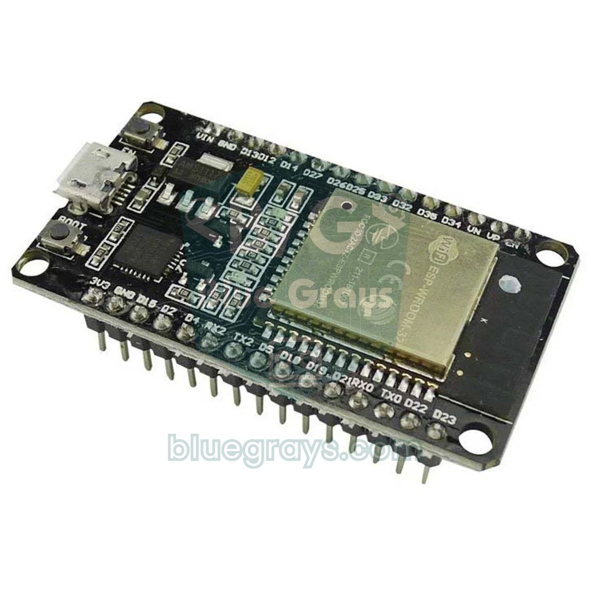
How do ESP32 touch pins work?
Each touch pin is connected to a measuring circuit inside the chip. This circuit keeps charging and discharging the pin and counts how many charge-discharge cycles complete in a fixed time. The wire and pad on the pin behave like a small capacitor. When you bring your finger close, your body adds a few picofarads to that capacitor, charging and discharging slow down, and fewer cycles complete in the same time. That's why on the classic ESP32 the touchRead value drops when you touch. With a short wire you'll usually see 40–80 when idle; when you touch it with a finger the value falls to around 10–25. These numbers depend on wire length, pad size, the board and the surroundings, so never hard-code a threshold from memory: measure it on your own setup.
| Feature | Classic ESP32 | ESP32-S2 / ESP32-S3 |
|---|---|---|
| Number of touch channels | 10 (T0–T9) | 14 (T1–T14) |
| Value when touched | Drops | Rises |
| Typical idle value | 40–80 | Thousands to tens of thousands |
| touchRead return type | uint16_t | uint32_t |
| Interrupt threshold | Absolute value, fires below it | Increase over the idle value |
| Deep sleep wake-up | Several pads | One pad |
ESP32 touch pin table (T0–T9)
The touch channels are wired only to specific GPIOs; if you use touchRead on any other pin you won't get a meaningful value. The Arduino core defines ready-made constants such as T0 and T1 for these channels, so writing touchRead(T0) in your code is the same as touchRead(4). Some of these pins are strapping pins that decide how the board starts up at boot; they work as touch pins, but they shouldn't be your first choice.
| Channel | GPIO | Usage note |
|---|---|---|
| T0 | GPIO 4 | Safe, first choice |
| T1 | GPIO 0 | Wired to the BOOT button, not broken out on 30-pin boards; avoid |
| T2 | GPIO 2 | Wired to the onboard LED, strapping pin; values may wander |
| T3 | GPIO 15 | Strapping pin (affects boot messages); use with care |
| T4 | GPIO 13 | Safe |
| T5 | GPIO 12 | Strapping pin (flash voltage); the board won't boot if it's held high at start-up |
| T6 | GPIO 14 | Safe, outputs a short PWM signal at boot |
| T7 | GPIO 27 | Safe |
| T8 | GPIO 33 | Safe |
| T9 | GPIO 32 | Safe |
Making pads: wire, aluminium foil and copper tape
Any conductive surface works as a touch pad. The simplest is the bare end of a jumper wire plugged into the pin. For a more comfortable surface you can use a 2×2 cm piece of aluminium foil or self-adhesive copper tape; copper tape also takes solder, so it's better for permanent projects. You can stick the pad to cardboard, the inside of a plastic box or the back of a piece of wood. A touch is also detected through 1–3 mm of plastic, acrylic or glass; the drop in value just gets smaller, so you need to measure the threshold again. Keep the wire from the pad to the ESP32 short: wires longer than 20–30 cm turn into antennas, and touching the wire itself triggers too.
| Pad material | Suggested size | Pros | Watch out |
|---|---|---|---|
| Jumper wire end | Wire tip | No preparation needed | Low sensitivity, for testing |
| Aluminium foil | 2×2 to 3×3 cm | Cheap, available everywhere | Won't take solder, attach the wire with tape or a clip |
| Copper tape | 1.5×1.5 to 3×3 cm | Takes solder, cuts cleanly | If the adhesive isn't conductive, solder the wire to the top |
| Perfboard or PCB pad | 1–2 cm diameter | Permanent and neat | A GND area around it reduces noise |
| Metal object (screw, door handle) | Depends on the object | Can make a hidden button | Large metal lowers the idle value a lot |
Reading touchRead values and setting a threshold
The first job is to see the real numbers on your own setup. The sketch below reads GPIO 4 (T0) and GPIO 27 (T7) eight times each and prints the average. If you open the Serial Plotter from the Tools menu in the Arduino IDE, you can watch both lines live and see how the values drop when you touch.
1// ESP32 dokunmatik değer okuma / ESP32 touch value reading
2// GPIO 4 = T0, GPIO 27 = T7
3
4void setup() {
5  Serial.begin(115200);
6  delay(500);
7}
8
9void loop() {
10  uint32_t t0 = 0, t7 = 0;
11  for (int i = 0; i < 8; i++) {      // 8 ölçümün ortalaması / average of 8 readings
12    t0 += touchRead(T0);
13    t7 += touchRead(T7);
14  }
15  Serial.print("T0:");
16  Serial.print(t0 / 8);
17  Serial.print(" T7:");
18  Serial.println(t7 / 8);            // Seri Çizici için / for the Serial Plotter
19  delay(100);
20}
While you watch the values, note three situations: the pad idle, a finger on the pad and a finger 1–2 cm above the pad. For example, if you read 62 idle, 14 when touched and 45 when approaching, a safe threshold is about 60 percent of the idle value, so around 37. Put the threshold too close to the idle value and it fires as a finger approaches; put it too low and you'll miss light touches.
| Situation | Example value | Comment |
|---|---|---|
| Idle, short wire and 2×2 cm foil | 55–70 | Reference value |
| Finger 1–2 cm away | 40–50 | Should not trigger |
| Finger touching | 10–20 | Definite touch |
| Touch through 1 mm of plastic | 25–35 | Raise the threshold a little |
| Long, dangling wire | Unstable, 30–70 | Shorten the wire, average the readings |
Self-calibrating touch button
Instead of hard-coding a threshold, it's far more reliable to measure the pad's idle value when the board starts and calculate the threshold from it. The sketch below averages 50 readings at start-up, treats a 40 percent drop as a touch and toggles the LED. It treats the pad as released when the value climbs back above 80 percent of the idle value. Using two separate thresholds is called hysteresis; it stops repeated triggering when the value jitters right at the limit. If you're curious about the mechanical side of buttons, see the how to wire a button article.
1// Otomatik kalibrasyonlu dokunmatik buton / self-calibrating touch button
2// GPIO 4 (T0) dokunma pedi, GPIO 2 kart üstü LED
3// GPIO 4 (T0) touch pad, GPIO 2 onboard LED
4
5const uint8_t DOKUNMA_PIN = T0;   // GPIO 4
6const uint8_t LED_PIN = 2;
7
8uint32_t bosDeger = 0;            // dokunulmamış değer / untouched value
9uint32_t basEsik, birakEsik;      // histerezisli eşikler / thresholds with hysteresis
10bool basili = false;
11bool ledDurum = false;
12
13uint32_t ortalamaOku(uint8_t pin, int adet) {
14  uint32_t toplam = 0;
15  for (int i = 0; i < adet; i++) {
16    toplam += touchRead(pin);
17    delay(2);
18  }
19  return toplam / adet;
20}
21
22void setup() {
23  Serial.begin(115200);
24  pinMode(LED_PIN, OUTPUT);
25  delay(300);                                  // açılışta pede dokunma / do not touch at boot
26  bosDeger = ortalamaOku(DOKUNMA_PIN, 50);
27  basEsik = bosDeger * 60 / 100;               // %40 düşüş = dokunma / 40% drop = touch
28  birakEsik = bosDeger * 80 / 100;             // %20 altına dönünce bırakıldı / released
29  Serial.printf("Bos: %u  Bas: %u  Birak: %u\n", bosDeger, basEsik, birakEsik);
30}
31
32void loop() {
33  uint32_t deger = ortalamaOku(DOKUNMA_PIN, 4);
34
35  if (!basili && deger < basEsik) {            // yeni dokunma / new touch
36    basili = true;
37    ledDurum = !ledDurum;
38    digitalWrite(LED_PIN, ledDurum);
39    Serial.println("Dokunuldu / touched");
40  } else if (basili && deger > birakEsik) {    // parmak çekildi / finger lifted
41    basili = false;
42  }
43  delay(20);
44}| Part of the code | Job |
|---|---|
| ortalamaOku() | Averages several readings to smooth out random spikes |
| bosDeger | The untouched value measured at start-up; restarting the board refreshes the calibration when conditions change |
| basEsik = 60% | A new touch is counted when the value falls below this |
| birakEsik = 80% | The finger counts as lifted when the value rises above this |
| basili variable | Stops the LED from toggling again and again while the finger stays |
Touch interrupts with touchAttachInterrupt
Instead of calling touchRead all the time, you can let the touch hardware measure in the background and call a function when the value drops below a threshold. That's what touchAttachInterrupt(pin, function, threshold) does. On the classic ESP32 the interrupt fires when the measured value falls below the threshold, and it keeps firing on every measurement cycle while the finger stays on the pad. So the interrupt function should only set a flag, and the real work should happen in loop() with a time check. We covered the general rules of interrupts in the Arduino interrupt article.
1// touchAttachInterrupt ile dokunma kesmesi / touch interrupt
2// GPIO 27 (T7) pedi; eşik touchRead ile ölçülerek seçilmeli
3// GPIO 27 (T7) pad; pick the threshold from your touchRead values
4
5const uint8_t PED = T7;            // GPIO 27
6const uint16_t ESIK = 40;          // ESP32: değer bunun ALTINA inince tetikler / fires below this
7volatile bool dokunuldu = false;
8
9void IRAM_ATTR dokunmaKesmesi() {
10  dokunuldu = true;                // kesmede yalnız bayrak / only set a flag in the ISR
11}
12
13void setup() {
14  Serial.begin(115200);
15  touchAttachInterrupt(PED, dokunmaKesmesi, ESIK);
16}
17
18void loop() {
19  static unsigned long sonDokunma = 0;
20  if (dokunuldu) {
21    dokunuldu = false;
22    // Parmak durdukça kesme tekrar tekrar gelir; 300 ms'de bir say
23    // The ISR repeats while the finger stays; count once per 300 ms
24    if (millis() - sonDokunma > 300) {
25      sonDokunma = millis();
26      Serial.printf("Dokunma! deger: %u\n", touchRead(PED));
27    }
28  }
29}
In this example the threshold is 40; that suits a pad that reads around 60 idle, otherwise change it according to the numbers from the reading sketch earlier. The IRAM_ATTR attribute on the interrupt function places it in fast memory; it's recommended for interrupt functions on the ESP32. To turn the interrupt off, call touchDetachInterrupt(pin). On the classic ESP32 you can also call touchInterruptSetThresholdDirection(false) so the interrupt fires when the value rises above the threshold; that's handy for catching the moment the finger lifts.
Three-pad touch slider
Three pads in a row are enough to find where your finger is. When your finger is between two pads, both values drop; by looking at how much each pad dropped you calculate the position with a weighted average. If you cut the pads as interlocking zigzag or chevron shapes instead of plain squares, your finger touches at least two pads at every position and the slider feels much smoother. Three strips of copper tape 1.5 cm wide with 1–2 mm gaps between them are a good start.
| Part | ESP32 pin | Note |
|---|---|---|
| Pad A (left) | GPIO 13 (T4) | Position 0 |
| Pad B (middle) | GPIO 14 (T6) | Position 500 |
| Pad C (right) | GPIO 33 (T8) | Position 1000 |
| LED | GPIO 26 | With a 220 Ω resistor, short leg to GND |
1// Üç pedli dokunmatik kaydırıcı ile LED parlaklığı / 3-pad touch slider dims an LED
2// Pedler: GPIO 13 (T4), GPIO 14 (T6), GPIO 33 (T8); LED: GPIO 26
3// Pads: GPIO 13 (T4), GPIO 14 (T6), GPIO 33 (T8); LED: GPIO 26
4
5const uint8_t pedler[3] = {T4, T6, T8};
6const uint8_t LED_PIN = 26;
7uint32_t bos[3];                   // her pedin boştaki değeri / idle value of each pad
8int parlaklik = 0;
9
10uint32_t oku(uint8_t pin) {
11  uint32_t t = 0;
12  for (int i = 0; i < 4; i++) t += touchRead(pin);
13  return t / 4;
14}
15
16void setup() {
17  Serial.begin(115200);
18  delay(300);
19  for (int p = 0; p < 3; p++) {
20    uint32_t t = 0;
21    for (int i = 0; i < 32; i++) t += touchRead(pedler[p]);
22    bos[p] = t / 32;
23  }
24}
25
26void loop() {
27  long fark[3];
28  long toplam = 0;
29  for (int p = 0; p < 3; p++) {
30    fark[p] = (long)bos[p] - (long)oku(pedler[p]);   // dokununca değer düşer / value drops on touch
31    if (fark[p] < 0) fark[p] = 0;
32    toplam += fark[p];
33  }
34
35  // Toplam düşüş boştaki değerin %25'ini geçerse parmak var
36  // A finger is present if the total drop exceeds 25% of an idle value
37  if (toplam > (long)bos[1] / 4) {
38    // Ağırlıklı ortalama: ped A = 0, ped B = 500, ped C = 1000
39    // Weighted average: pad A = 0, pad B = 500, pad C = 1000
40    long konum = (fark[1] * 500L + fark[2] * 1000L) / toplam;
41    parlaklik = map(konum, 0, 1000, 0, 255);
42    analogWrite(LED_PIN, parlaklik);
43    Serial.printf("Konum: %ld  Parlaklik: %d\n", konum, parlaklik);
44  }
45  delay(30);
46}
At start-up the sketch saves each pad's idle value, then calculates the drops in every loop. If the total drop is large enough, a finger is on the slider and the position is found between 0 and 1000. We convert that value to 0–255 with map() and send it to the LED with analogWrite(). analogWrite() works in both the 2.x and 3.x versions of the ESP32 Arduino core. You'll find how PWM works in the what is PWM article.
Waking from deep sleep by touch
In a battery project you can put the ESP32 into deep sleep and wake it only when someone touches the pad. In this mode the cores are off, but the touch measuring circuit keeps running at low power. The touchSleepWakeUpEnable(pin, threshold) function sets the threshold and enables touch wake-up in one go. On the classic ESP32 you can use several pads as wake-up sources; on the ESP32-S2 and S3 only one pad is allowed. After waking, esp_sleep_get_touchpad_wakeup_status() tells you which pad woke the board. We covered deep sleep details and current figures in the ESP32 deep sleep article.
1// Dokunarak deep sleep'ten uyanma / wake from deep sleep by touch
2// GPIO 27 (T7) pedi / GPIO 27 (T7) pad
3
4#if CONFIG_IDF_TARGET_ESP32
5  #define ESIK 40      // ESP32: değer bunun altına inerse uyanır / wakes below this value
6#else
7  #define ESIK 5000    // ESP32-S2/S3: boştaki değere göre artış / rise above the baseline
8#endif
9
10RTC_DATA_ATTR int uyanmaSayisi = 0;   // uykuda korunur / kept during deep sleep
11
12void setup() {
13  Serial.begin(115200);
14  delay(500);
15  uyanmaSayisi++;
16
17  if (esp_sleep_get_wakeup_cause() == ESP_SLEEP_WAKEUP_TOUCHPAD) {
18    Serial.printf("Dokunmayla uyandi, ped: %d\n", (int)esp_sleep_get_touchpad_wakeup_status());
19  } else {
20    Serial.println("Ilk acilis ya da baska neden / first boot or other cause");
21  }
22  Serial.printf("Uyanma sayisi: %d\n", uyanmaSayisi);
23
24  // Burada ölçüm yap, veri gönder... / take readings, send data here...
25  delay(2000);
26
27  touchSleepWakeUpEnable(T7, ESIK);   // T7 pedini uyandırma kaynağı yap / enable T7 as wake source
28  Serial.println("Uyuyorum / going to sleep");
29  Serial.flush();
30  esp_deep_sleep_start();
31}
32
33void loop() {
34}
After waking, the code starts again from setup(), because RAM is cleared in deep sleep. To keep the wake-up count we put RTC_DATA_ATTR in front of the variable; such variables live in the small RTC memory that's kept during sleep. Because touch measurement continues while asleep, deep sleep current is slightly higher than with timer wake-up; keep that in mind when you estimate battery life. The #if block in the code lets the same program compile with the right threshold on the ESP32-S2 and S3 too.
ESP32 touch pins with MicroPython
If you've flashed MicroPython onto your ESP32, you do the same thing with the TouchPad class in the machine module. Its read() method returns the same value as touchRead() in Arduino; on the classic ESP32 it still drops when touched. For wake-up you use esp32.wake_on_touch(True) and the pad's config(threshold) method.
1# ESP32 MicroPython dokunmatik pin / ESP32 MicroPython touch pin
2from machine import Pin, TouchPad
3import time
4
5ped = TouchPad(Pin(4))       # GPIO 4 = T0
6led = Pin(2, Pin.OUT)        # kart üstü LED / onboard LED
7
8bos = sum(ped.read() for _ in range(20)) // 20   # dokunulmamış değer / idle value
9esik = bos * 6 // 10
10basili = False
11
12while True:
13    deger = ped.read()
14    if not basili and deger < esik:
15        basili = True
16        led.value(not led.value())   # her dokunuşta LED'i değiştir / toggle on every touch
17        print("dokunuldu", deger)
18    elif basili and deger > bos * 8 // 10:
19        basili = False
20    time.sleep_ms(30)
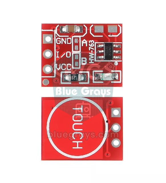
The Raspberry Pi Pico has no built-in capacitive touch sensor. If you want a touch button with a Pico or an Arduino Uno, the easiest solution is a ready-made TTP223 module; it detects the touch on its own and gives you an ordinary digital signal.
Humidity, water and noise problems
Capacitive sensing detects water as well as fingers. A drop of water or heavy humidity on the pad increases the capacitance, the value drops and the button can trigger by itself. In bathroom, kitchen or outdoor projects, place the pad behind a surface that doesn't hold water, choose a slightly lower threshold and require the touch to last at least 50–100 ms. Long wires, nearby relays and motors and a poor USB power supply also make the values wander. The table below sums up the most common problems and their fixes.
| Problem | Likely cause | Fix |
|---|---|---|
| Triggers by itself | Threshold too close to the idle value | Lower the threshold to 60% of idle, add hysteresis |
| Values keep fluctuating | Long or dangling wire, noisy power | Shorten the wire, average 4–8 readings, use a good USB cable |
| Sensitivity changed when unplugged from the computer | The ground reference changed | Calibrate on the final setup, with the battery or adapter |
| Triggers in humidity or with a water drop | Water increases capacitance | Put the pad behind a cover, require a minimum touch time |
| A pin never changes | A non-touch GPIO was used | Check the pin table; GPIO 34–39 are not touch pins |
| The board won't boot | The pad and wire on GPIO 12 disturb booting | Move the pad to GPIO 4, 13, 27, 32 or 33 |
Touch pins on the ESP32-S3 and other models
The ESP32-S2 and ESP32-S3 use second-generation touch hardware and differ from the classic ESP32 in three important ways. First, the channels are on GPIO 1–14 and there are 14 of them; T1 is GPIO 1 and T14 is GPIO 14. Second, the values are much larger and rise when touched; a pad that reads about 20,000 idle can go above 40,000 when touched. Third, the threshold in touchAttachInterrupt and touchSleepWakeUpEnable isn't an absolute value but an increase over the idle value. On the S3 you can also use touchInterruptGetLastStatus(pin) to find out whether the pad is still pressed. The ESP32-C3 and ESP32-C6 have no touch sensor at all. If you write code for more than one model, separate them with CONFIG_IDF_TARGET_ESP32 as in the wake-up example.
Project ideas with touch pins
- Desk lamp: an invisible on/off switch made of copper tape stuck behind a wooden cover, with a long touch to adjust brightness.
- Slider dimmer: change the brightness and colour of a WS2812B LED strip with a three-pad slider.
- Battery-powered doorbell or note device: the ESP32 waits in deep sleep, wakes when the pad is touched and sends a notification over Wi-Fi.
- Fruit piano: a toy with wires to bananas and apples that plays a different note for each fruit; a buzzer can make the sound.
- Hidden code panel: a lock that opens when four pads hidden inside a box are touched in the right order.
The ESP32's touch pins give your project a touch interface with a few centimetres of foil and a few lines of code. In the BlueGrays app you'll find projects such as ESP32 LED blinking, controlling an LED with a button, LED brightness with PWM and deep sleep, each with a step-by-step circuit diagram and code; swap the buttons for the touch pads in this guide to build your own version.
Frequently asked questions
How many touch pins does the ESP32 have?
The classic ESP32 has 10 capacitive touch channels: T0–T9, which are GPIO 4, 0, 2, 15, 13, 12, 14, 27, 33 and 32. The ESP32-S2 and ESP32-S3 have 14 channels on GPIO 1–14. The ESP32-C3 and C6 have no touch sensor.
What should the ESP32 touchRead value be?
On the classic ESP32 with a short wire you usually read 40–80 when idle and 10–25 when touched. The exact number depends on the wire, pad size and surroundings. Measuring on your own setup and choosing about 60 percent of the idle value as the threshold is a good start.
How do I set the ESP32 touch threshold?
First measure the pad's idle and touched values with touchRead. On the classic ESP32 put the threshold between them, usually at 60 percent of the idle value. The most robust method is to measure the idle value at start-up, calculate the threshold in code and add hysteresis.
Can an ESP32 touch pin wake it from deep sleep?
Yes. Use touchSleepWakeUpEnable(pin, threshold) to make the pad a wake-up source, then call esp_deep_sleep_start(); the board restarts when the pad is touched. The classic ESP32 supports several pads, the ESP32-S2 and S3 support one.
Why does my ESP32 touch pin trigger by itself?
Usually the threshold is too close to the idle value, the pad wire is long or there's humidity. Lower the threshold, average several readings, add hysteresis and shorten the wire. It also matters to calibrate with the power supply the board will finally use.
Why does ESP32-S3 touchRead increase when touched?
The ESP32-S2 and S3 use second-generation touch hardware in which the measured value rises with capacitance. So on the S3 the value goes up when touched and is in the tens of thousands. The interrupt and wake-up threshold is also an increase over the idle value, not an absolute number.
Projects to build after reading this
See all projects
LED Blink with ESP32
Teaches basic GPIO output usage with ESP32. We achieve a blinking effect by turning an LED on and off from a digital pin. ESP32 version of the classic blink project on Arduino UNO; the basic blink commands in the Arduino environment are the same, but the ESP32's pin layout and 3.3 V GPIO levels differ from those of the Arduino UNO.

ESP32 LED Control with Pushbutton (Toggle)
Each time the button is pressed the state of the LED changes: if it is on it turns off, if it is off it turns on. Classic toggle pattern. With debounce we clean up the mechanical noise of the pushbutton to ensure a single toggle with a single press.

ESP32 Built-in LED Blink
Blinking the built-in blue LED on the ESP32 DevKit V1. No external components required! The first project you should try when you buy an ESP32. GPIO 2 is connected to the built-in LED.

ESP32 LED Fade with PWM
Smoothly changing the brightness of the LED from 0 to max, from max to 0. We control PWM with analogWrite() as in Arduino - the same syntax as ESP32 Arduino Core 3.0+ works without problems. Pin definition + pinMode + analogWrite is enough.

ESP32 RGB LED Control
Unlimited color generation with a single RGB LED instead of 3 separate LEDs. As in Arduino, we make a rainbow transition by setting the R/G/B values with analogWrite(). Color theory (such as red+green=yellow) is seen practically.

ESP32 Deep Sleep — Battery Saving (OLED + RTC RAM Counter)
The ESP32's Deep Sleep mode reduces current consumption to ~10 µA by shutting down the CPU and most peripherals, making it critical for battery-powered IoT devices. In this project, we use three different wake-up sources: a timer (15 seconds), an external pin (EXT0 — button GPIO 33), and touch (T0/GPIO 4). Variables marked with RTC_DATA_ATTR are preserved during deep sleep—the boot counter, timer wake counter, and button wake counter are continuously tracked. On each wake-up, the SSD1306 OLED

ESP32 Color Mixer Light (3 Potentiometers + RGB LED + OLED)
A smart color-mixing lamp that lets you mix any color you want by turning three potentiometers with the ESP32! As you turn the red, green, and blue potentiometers, the common-cathode RGB LED changes color in real time. The SSD1306 OLED display shows real-time values for each color in the 0–255 range, visual fill bars, and the HEX web color code (such as #FF8040). A mini professional color studio—teaches RGB color theory, ADC analog reading, brightness control via PWM, and I2C display design all

ESP32 Smart Lighting (PIR + LDR + Relay + OLED)
Turn your hallway, bathroom, or pantry into smart lighting with ESP32! Using a PIR motion sensor, LDR light sensor, and a relay module, we build the classic "light turns on when motion is detected in the dark" scenario — if the environment is already bright, motion does NOT trigger the light, saving energy during the day. The light stays on for 30 seconds; if motion continues, the timer resets and the light stays on longer. The SSD1306 OLED shows large-font status (ON / DAYTIME / WAITING), a cou