
TTP223 Touch Sensor with Arduino: Modes, Wiring and a Touch Lamp
How to use the TTP223 capacitive touch sensor: A/B jumpers for momentary or toggle mode, an Arduino touch lamp, sensing through plastic, ESP32 and Pico code.
The TTP223 touch sensor is a cheap single-key capacitive touch module that replaces a mechanical push button by detecting your finger through a change in capacitance. It has only three pins (VCC, GND and I/O): when you touch it, the output goes HIGH, and when you take your finger away it drops back to LOW. That simplicity means you read it on an Arduino with digitalRead() just like a button, and because it runs on 2–5.5 V it also connects directly to an ESP32 or a Raspberry Pi Pico. With no moving parts it doesn't wear out or click, and it can be hidden behind a thin layer of plastic, glass or wood.
In this guide you'll learn step by step what happens inside the TTP223, how to use the A and B solder jumpers on the board to choose momentary or toggle mode and an active-high or active-low output, how to build an Arduino touch lamp that switches with a short touch and dims with a long one, how to make the sensor work behind a panel, how to use several keys, how it compares with the ESP32's built-in touch pins, and how to use it on the Pico with MicroPython.
What is the TTP223 touch sensor and how does it work?
The copper pad on the module and the board's ground (GND) area form a tiny capacitor of a few picofarads. When your finger approaches the pad, your body is added to that capacitor and the total capacitance rises by a few picofarads. The roughly 1 MHz sensor oscillator inside the TTP223 sees this rise as a change in frequency, compares the result with a reference value it keeps, and switches the output if the difference is large enough. The parallel-plate capacitor formula C = ε·A/d applies here too: the larger the pad area (A) and the thinner the material between finger and pad (d), the stronger the detection.
The chip sets its reference value by itself. The moment you apply power, it measures its surroundings for about 0.5 seconds and ignores touches during that time. After that, as long as nobody touches it, it recalibrates itself roughly every 4 seconds, so slow changes such as temperature and humidity are compensated over time. This is why the sensor treats whatever is around the pad at power-up as "untouched": if your finger is on the pad when it powers up, it won't see you at all.
| Feature | Value |
|---|---|
| Chip | TTP223-BA6 (6-pin SOT-23 package) |
| Supply voltage | 2.0–5.5 V |
| Chip current (3 V, without LED) | Typically 1.5 µA, max 3 µA |
| Response time | Up to ~220 ms in low-power mode, ~60 ms in fast mode |
| Output type | CMOS (push-pull); the HIGH level equals VCC |
| Output current (at 3 V) | Sources about 4 mA, sinks 8 mA |
| Power-on calibration | About 0.5 s (don't touch during this time) |
| Sensitivity adjustment | 0–50 pF capacitor (Cs) between pad and GND |
| Operating temperature | -20 to +70 °C |
| Module pins | VCC, I/O (SIG or OUT), GND |
In the TTP223-BA6 version used on these modules some options are fixed inside the package: the chip always runs in low-power mode, and the 100-second "maximum on time" limit found in other packages is disabled. In low-power mode the chip draws only a few microamps, but it can take up to about 220 ms to respond to the first touch. Once a touch is detected it stays in fast mode for about 12 seconds and responds much more quickly to the next touches. You won't notice this delay in a lamp or a doorbell, but keep it in mind if you're building a game controller that needs fast reactions.
TTP223 pinout and wiring
| TTP223 pin | Arduino Uno | ESP32 | Raspberry Pi Pico |
|---|---|---|---|
| VCC | 5V | 3V3 | 3V3(OUT) (pin 36) |
| GND | GND | GND | GND (pin 38) |
| I/O (SIG) | D2 | GPIO 26 | GP15 (pin 20) |
Since the output pin actively drives the signal HIGH and LOW, you don't need INPUT_PULLUP or an external resistor on the Arduino; simply setting the pin as INPUT is enough. There's no contact bounce like with mechanical buttons, because the chip only changes its output once the touch is stable. Still, if you want your code to count one touch as a single event, use the edge-detection logic we explain in How to Connect a Button.
Choosing the mode with the A and B solder jumpers
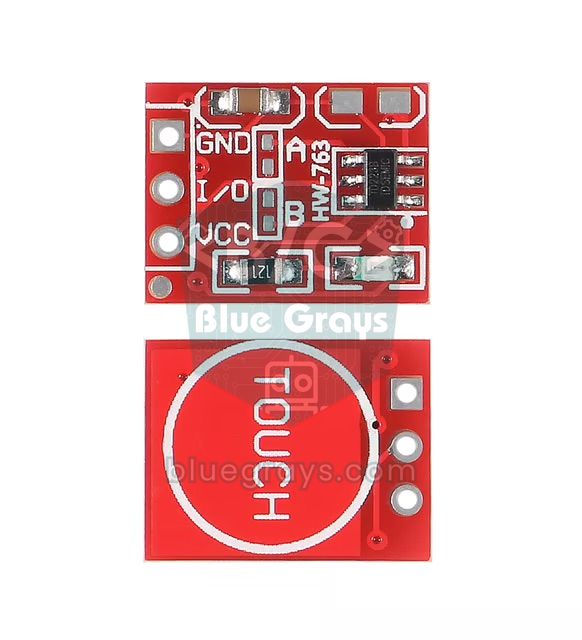
Next to the chip on the module there are two small pairs of solder pads marked A and B. They're connected to two option pins of the chip: on most modules A selects whether the output is active high or active low (AHLB), and B selects whether the sensor works in momentary or toggle mode (TOG). Inside the chip these pins are pulled to GND through a resistor, so with the pads open the option is "0"; bridge the two pads with a blob of solder and the option becomes "1". After changing a jumper, the safest approach is to remove and reapply power. If the markings on your board are different, you can easily confirm the mode with the LED in the first test sketch.
| A | B | Mode | When touched | Output at power-up |
|---|---|---|---|---|
| Open | Open | Momentary, active high (factory default) | HIGH for as long as you touch | LOW |
| Bridged | Open | Momentary, active low | LOW for as long as you touch | HIGH |
| Open | Bridged | Toggle (latching), active high | State flips on every touch | LOW |
| Bridged | Bridged | Toggle (latching), active low | State flips on every touch | HIGH |
First test with Arduino: reading a touch
- Connect the module's VCC pin to the Arduino's 5V pin, GND to GND and the I/O pin to D2.
- Upload the sketch below and open the Serial Monitor at 9600 baud.
- After the board starts, wait about a second without touching the pad; the chip calibrates itself during this time.
- Touch the pad with your finger: the Arduino's built-in LED on pin 13 (and, on most modules, the board's own LED) should light up and the touch count in the Serial Monitor should go up by one.
- The LED stays on for as long as your finger is on the pad, while the counter only goes up once for each new touch.
1const int TOUCH_PIN = 2;    // TTP223 I/O (SIG) pini / TTP223 I/O (SIG) pin
2const int LED_PIN = 13;     // Uno'nun dahili LED'i / Uno onboard LED
3
4bool lastState = false;
5unsigned long touchCount = 0;
6
7void setup() {
8  Serial.begin(9600);
9  pinMode(TOUCH_PIN, INPUT);   // çıkış push-pull, pull-up gerekmez / push-pull output, no pull-up needed
10  pinMode(LED_PIN, OUTPUT);
11  delay(600);                  // açılış kalibrasyonu bitsin (~0,5 s) / let power-on calibration finish (~0.5 s)
12}
13
14void loop() {
15  bool state = digitalRead(TOUCH_PIN) == HIGH;   // dokunurken true / true while touched
16  digitalWrite(LED_PIN, state ? HIGH : LOW);
17
18  if (state && !lastState) {   // LOW -> HIGH: yeni dokunuş / new touch
19    touchCount++;
20    Serial.print("Dokunus / Touch: ");
21    Serial.println(touchCount);
22  }
23  lastState = state;
24}
The most important part of the code is edge detection. The previous reading is stored in the lastState variable; if the new reading is HIGH and the previous one was LOW, that's a new touch. Without this check the counter would go up on every pass of the loop while your finger stays on the pad, which means thousands of times per second. The 600 ms wait in setup() makes sure the chip has finished calibrating when the Arduino and the module are powered at the same time. We chose D2 because it's one of the Uno's interrupt pins; if you like, you can also catch the touch with an interrupt using attachInterrupt(digitalPinToInterrupt(2), function, RISING).
Project: an Arduino touch lamp
Now let's build a real touch lamp: a short touch switches the lamp on and off, holding your finger on the pad while it's on slowly dims the light, and the next long touch brightens it again. Since the brightness is set with PWM, we connect the lamp to D9, one of the Uno's PWM pins. For testing, an LED and a 220 Ω resistor on D9 are enough (use the LED resistor calculator for the right value). If you're using a 12 V LED strip, put a logic-level MOSFET such as the IRLZ44N in between; see Using a MOSFET with Arduino for details.
1const int TOUCH_PIN = 2;                // TTP223 I/O (fabrika ayarı: anlık, aktif yüksek) / factory default: momentary, active high
2const int LAMP_PIN = 9;                 // PWM pini: LED ya da MOSFET kapısı / PWM pin: LED or MOSFET gate
3const unsigned long LONG_PRESS = 600;   // uzun dokunuş eşiği (ms) / long-touch threshold (ms)
4
5bool lampOn = false;
6bool lastTouch = false;
7bool dimming = false;
8int brightness = 255;                   // son parlaklık (10-255) / last brightness (10-255)
9int step = 5;                           // kısma yönü ve adımı / dimming direction and step
10unsigned long touchStart = 0;
11unsigned long lastStep = 0;
12
13void setup() {
14  pinMode(TOUCH_PIN, INPUT);
15  pinMode(LAMP_PIN, OUTPUT);
16  delay(600);                           // TTP223 kalibrasyonu bitsin / let the TTP223 finish calibrating
17}
18
19void loop() {
20  bool touch = digitalRead(TOUCH_PIN) == HIGH;
21  unsigned long now = millis();
22
23  if (touch && !lastTouch) {            // dokunuş başladı / touch started
24    touchStart = now;
25    dimming = false;
26  }
27
28  if (touch && lampOn && now - touchStart > LONG_PRESS) {   // lamba açıkken uzun dokunuş / long touch while the lamp is on
29    if (!dimming) {
30      dimming = true;
31      step = -step;                     // her uzun dokunuşta yön değişir / direction flips on every long touch
32    }
33    if (now - lastStep >= 20) {         // 20 ms'de bir adım / one step every 20 ms
34      lastStep = now;
35      brightness += step;
36      if (brightness <= 10 || brightness >= 255) {
37        brightness = constrain(brightness, 10, 255);
38        step = -step;                   // uca gelince geri dön / bounce back at the ends
39      }
40      analogWrite(LAMP_PIN, brightness);
41    }
42  }
43
44  if (!touch && lastTouch && !dimming) {   // kısa dokunuş bitti: aç/kapa / short touch ended: toggle
45    lampOn = !lampOn;
46    analogWrite(LAMP_PIN, lampOn ? brightness : 0);
47  }
48
49  lastTouch = touch;
50}| Code part | What it does |
|---|---|
| touchStart | Records the moment the touch started using millis() |
| LONG_PRESS = 600 | Touches longer than 600 ms count as a dimming command |
| dimming | Set when dimming happened during this touch, so the lamp doesn't switch off when you lift your finger |
| step | Changes sign on every long touch, so the light dims one time and brightens the next |
| constrain(brightness, 10, 255) | Keeps the brightness in a range where the lamp never goes fully dark |
| Toggle on release | The decision is made when the finger lifts, so short and long touches can be told apart |
Notice that there's no delay() anywhere in the code: all the timing is done with millis(), so the loop keeps running and never misses a touch. You can read more about this technique in millis() vs delay(). Because the last brightness stays in the brightness variable, the light comes back at the level you last set when you switch the lamp off and on again, just like the touch desk lamps you find in shops.
Sensing through thin materials
The TTP223's most popular feature is that it can work from inside a box with no holes. Plastic, acrylic, glass, wood, paper and fabric let the electric field through; the material between pad and finger acts like the dielectric of a capacitor. As the material gets thicker, d in the formula grows and the capacitance between finger and pad falls; doubling the thickness roughly halves that capacitance. Glass has a higher dielectric constant than most plastics, so glass of the same thickness usually gives better results. In practice the module usually works fine behind a 1–3 mm plastic, acrylic or glass panel; with thicker panels you'll need a bigger pad, and you should always test with your own material.
- Don't leave an air gap: Air has a dielectric constant of 1, and even a 1 mm gap seriously reduces sensitivity. Stick the module firmly to the panel, pad side facing it, with thin double-sided tape or glue.
- Make the pad bigger: For a larger touch area, cut an electrode from copper tape or aluminium foil, gently scrape the protective coating off one corner of the pad and solder the electrode to it with a very short wire. The longer the wire, the more capacitance it adds and the less stable the sensor becomes.
- Avoid metal: Metal panels, materials with metal content and metallic paints collect the electric field on themselves; the sensor either detects nothing or triggers by itself.
- Turn down excessive sensitivity: If the sensor triggers before your finger gets close, add a small 5–20 pF ceramic capacitor (Cs) between the pad and GND; the larger the value, the lower the sensitivity, with 50 pF as the upper limit. You can decode the marking on the capacitor (e.g. 100 = 10 pF, 220 = 22 pF) with the capacitor code tool.
- Mount first, then power up: Because the chip takes its surroundings as the reference at power-up, apply power only after the panel and lid are in place. If you fit the panel while it's powered, the chip may treat it as a permanent touch; in that case simply remove and reapply power.
Using several touch keys
Each TTP223 monitors its own pad independently; if you want four keys, connect four modules to four separate digital pins, with the modules sharing VCC and GND. If the keys are very close together, your finger may also affect the neighbouring pad; leave at least 1–2 cm between pads and keep the modules away from motor or relay wires. The sketch below uses four TTP223s and a passive buzzer to make a small touch piano: whichever key you touch plays its note, and the sound stops when you lift your finger.
1const int TOUCH_PINS[] = {2, 3, 4, 5};          // dört TTP223 I/O pini / four TTP223 I/O pins
2const int NOTES[]      = {262, 294, 330, 349};  // Do, Re, Mi, Fa (Hz) / C4, D4, E4, F4 (Hz)
3const int KEY_COUNT    = 4;
4const int BUZZER_PIN   = 8;                     // pasif buzzer / passive buzzer
5
6int currentNote = 0;
7
8void setup() {
9  for (int i = 0; i < KEY_COUNT; i++) {
10    pinMode(TOUCH_PINS[i], INPUT);
11  }
12  pinMode(BUZZER_PIN, OUTPUT);
13  delay(600);                                   // sensörlerin kalibrasyonu / sensor calibration
14}
15
16void loop() {
17  int note = 0;
18  for (int i = 0; i < KEY_COUNT; i++) {
19    if (digitalRead(TOUCH_PINS[i]) == HIGH) {   // ilk dokunulan tuş çalar / the first touched key plays
20      note = NOTES[i];
21      break;
22    }
23  }
24  if (note != currentNote) {                    // yalnızca nota değişince güncelle / update only when the note changes
25    currentNote = note;
26    if (note > 0) tone(BUZZER_PIN, note);
27    else noTone(BUZZER_PIN);
28  }
29}
Since tone() can only play one note at a time, the code picks the first key that's touched and only updates the note when it changes, so the sound doesn't crackle. On the Uno, tone() uses Timer2, so analogWrite doesn't work on pins 3 and 11 while the buzzer is playing; that's no problem here because the piano only uses D3 as an input. As the number of keys grows, it's neater to switch to multi-channel chips instead of one module per key: the TTP224 provides four keys with four separate outputs, the TTP229 reads 8 or 16 keys over a two-wire serial interface, and the MPR121 monitors 12 electrodes over I2C.
ESP32: TTP223 or the built-in touch pins?
The classic ESP32 has a capacitive touch sensor built in, and 10 pins (T0–T9) can be used as touch keys without any module: GPIO 4, 0, 2, 15, 13, 12, 14, 27, 33 and 32, in that order. The touchRead() function returns a raw number; on the classic ESP32 this number falls when you touch the pin, while on the ESP32-S2 and S3 it rises. The ESP32-C3 has no touch sensor at all. For a detailed look at the built-in pins see ESP32 touch pins; the table below compares the two approaches.
| Feature | TTP223 module | ESP32 built-in touch |
|---|---|---|
| Extra part | Needed (1 key per module) | Not needed; a wire or copper pad on the pin is enough |
| Output | Ready-made digital HIGH/LOW | Raw number; you choose the threshold |
| Calibration | Done by the chip itself | You measure and set a threshold in code |
| Which boards? | All of them (Uno, Nano, ESP, Pico) | Only the ESP32, ESP32-S2 and ESP32-S3 |
| Number of keys | As many as you have modules | 10 on the ESP32, 14 on the S2 and S3 |
| Wake from deep sleep | Via ext0/ext1 on an RTC GPIO | With touchSleepWakeUpEnable() |
| Long wires and humidity | Stable, because the pad sits on the module | Readings drift as wires get longer and the threshold stops working |
1const int TTP223_PIN = 26;   // TTP223 I/O, modül 3,3 V ile beslenir / module powered from 3.3 V
2const int TOUCH_GPIO = 4;    // dahili dokunmatik T0 / built-in touch pad T0
3const int LED_PIN = 2;       // çoğu DevKit'te dahili LED / onboard LED on most DevKits
4int threshold = 0;
5
6void setup() {
7  Serial.begin(115200);
8  pinMode(TTP223_PIN, INPUT);
9  pinMode(LED_PIN, OUTPUT);
10  delay(600);                                  // dokunmadan bekle / wait without touching
11  threshold = touchRead(TOUCH_GPIO) * 0.7;     // dokunulmamış değerin %70'i / 70% of the untouched value
12}
13
14void loop() {
15  int raw = touchRead(TOUCH_GPIO);             // klasik ESP32'de dokununca düşer / drops when touched on the classic ESP32
16  bool builtIn = raw < threshold;
17  bool module = digitalRead(TTP223_PIN) == HIGH;
18  digitalWrite(LED_PIN, (builtIn || module) ? HIGH : LOW);
19  Serial.printf("ham/raw: %d  esik/threshold: %d  T0: %d  TTP223: %d\n", raw, threshold, builtIn, module);
20  delay(100);
21}
At startup this sketch measures the untouched T0 value and uses 70% of it as the threshold; watch the raw value in the Serial Monitor (115200 baud) to tune the ratio for your own wiring. If you're using an ESP32-S3, the value rises when touched, so reverse the comparison (for example threshold = measured value × 1.3 and raw > threshold). Another reason we connected the TTP223 to GPIO 26 is that it's an RTC GPIO: with esp_sleep_enable_ext0_wakeup(GPIO_NUM_26, 1) you can put the ESP32 into deep sleep and wake it with a touch. Since the TTP223 draws only a few microamps, the two make a great pair for battery-powered projects; see ESP32 deep sleep for details.
TTP223 with the Raspberry Pi Pico (MicroPython)
The Pico's RP2040 chip has no touch sensor, so the TTP223 is the easiest way to add a touch key to a Pico. Power the module from the 3V3(OUT) pin (physical pin 36) and connect the I/O pin to GP15 (physical pin 20). The MicroPython code below toggles the board's built-in LED on every touch. Because it catches the touch with an interrupt (IRQ), no touch is missed even while the main loop is busy with other work. If you don't know yet how to install MicroPython on the Pico, start with What Is the Raspberry Pi Pico?.
1from machine import Pin
2import time
3
4touch = Pin(15, Pin.IN)            # TTP223 I/O -> GP15 (fiziksel pin 20) / physical pin 20
5led = Pin("LED", Pin.OUT)          # dahili LED (Pico ve Pico W) / onboard LED (Pico and Pico W)
6last = 0
7
8def on_touch(pin):
9    global last
10    now = time.ticks_ms()
11    if time.ticks_diff(now, last) > 250:   # bir dokunuşu bir kez say / count each touch once
12        led.toggle()
13        last = now
14
15time.sleep_ms(600)                 # TTP223 açılış kalibrasyonu / TTP223 power-on calibration
16touch.irq(trigger=Pin.IRQ_RISING, handler=on_touch)
17
18while True:
19    print("Dokunma / Touch:", touch.value(), " LED:", led.value())
20    time.sleep(1)
In current MicroPython versions the name Pin("LED") selects the built-in LED on both the Pico and the Pico W. If you've bridged jumper B and put the module in toggle mode, you don't even need the interrupt: writing led.value(touch.value()) in the loop is enough, because the chip itself now keeps the on/off state. Although the chip's output doesn't bounce, the 250 ms lockout in the code stops short noise pulses on long wires from toggling the LED twice.
TTP223 project ideas
- Touch night light: Add an LDR so the lamp only responds to touch when it's dark.
- Colour-changing lamp: Change the colour of a WS2812B NeoPixel ring with every touch and set the brightness with a long touch.
- Hidden code lock: Place four TTP223s behind an acrylic panel; touching the keys in the right order makes a servo motor open the lock.
- Doorbell with no holes: Stick the sensor inside a plastic box; a touch makes a DFPlayer Mini play a chime.
- Touch socket switch: Switch a desk lamp or a fan on and off with a relay module.
- Battery-powered remote: Keep an ESP32 in deep sleep; when you touch the TTP223 it wakes up and sends a command with ESP-NOW.
Common mistakes and how to fix them
| Symptom | Likely cause | Fix |
|---|---|---|
| No response to touch | A finger was on the pad at power-up, or the panel is too thick | Take your hand away and power-cycle; use a thinner panel or a larger pad |
| Triggers by itself | Too sensitive, metal near the pad, noisy power adapter | Add 5–20 pF between pad and GND, move metal away, put 100 nF across VCC–GND |
| Stays as if touched all the time | The panel or lid was fitted while powered | Mount first, then apply power |
| Counter goes up several times per touch | The code reads the level, not the edge | Store the previous state and count only on the LOW→HIGH transition |
| First touch is detected with a delay | The chip is in low-power mode (~220 ms) | That's normal; following touches are detected faster |
| ESP32 or Pico pin damaged | The module was powered from 5 V | Always power the module from the 3V3 pin |
| In toggle mode the lamp starts on at power-up | Jumper A selects active low | Choose the power-up state with jumper A or invert the logic in code |
The TTP223 is the easiest way to add a modern touch interface to your projects with a very cheap module: it replaces the mechanical button, works behind panels with no holes and gets along with every microcontroller. First try reading it with the factory settings, then practise edge detection and long-touch logic with the lamp and piano examples. In the BlueGrays app you'll find step-by-step circuit diagrams and code for lighting an LED with a button, an on/off toggle LED, ESP32 and Pico button projects and switching a mains bulb, and you can turn all of them into touch projects by fitting a TTP223 in place of the button.
Frequently asked questions
What voltage does the TTP223 work with?
The TTP223 chip works from 2.0 to 5.5 V; on an Arduino Uno it's powered from 5 V, and on an ESP32 or Raspberry Pi Pico from 3.3 V. Because the output's HIGH level equals the supply voltage, always power the module with the logic voltage of the board it's connected to.
What are the A and B pads on the TTP223 for?
A and B are option jumpers that you close with solder. On most modules jumper A makes the output active low (LOW when touched), and jumper B puts the sensor into toggle mode, where the output flips with each touch and stays that way. With both open, the module is in momentary mode and outputs HIGH for as long as you touch it.
Does the TTP223 work through glass or plastic?
Yes, it works through plastic, acrylic, glass, wood and paper as long as they contain no metal. In practice panels 1–3 mm thick are usually fine; thicker panels need a pad enlarged with copper tape. Remember to stick the module to the panel without leaving an air gap.
Why does my TTP223 trigger by itself?
The most common causes are too much sensitivity, metal parts near the pad, long electrode wires and a noisy power supply. Adding a 5–20 pF capacitor between the pad and GND lowers the sensitivity. Putting a 100 nF capacitor across VCC and GND and using a good-quality adapter usually solves the problem too.
How do I switch a mains lamp with a TTP223?
The TTP223 output can only supply a few milliamps, so it can't drive a lamp or a relay coil directly. Connect the sensor to an Arduino and let the Arduino drive a relay module; the relay can only switch on and off, not dim. Keep the mains wiring in a closed enclosure and never stick the pad onto a surface connected to mains voltage.
Do I need a TTP223 for touch on the ESP32?
No; the classic ESP32's 10 touch pins can be used directly with touchRead(). However, you have to set the threshold in software, and readings drift on long wires. If you want a ready-made, stable digital output, or you're using a board without touch pins such as the ESP32-C3, the TTP223 is more practical.
Projects to build after reading this
See all projects
Toggle an LED with a Button (On/Off)
Press the button once and the light comes on, press it again and it goes off, just like the light switch in your room. The Arduino notices every press and flips the LED to the opposite state, waiting

LED Control with a Push Button (Push)
Just like a doorbell: the light stays on as long as you press, and goes off when you let go. The Arduino keeps listening to the button; while it's pressed the LED is on, and the moment you lift your f

ESP32 LED Control with Pushbutton (Toggle)
Each time the button is pressed the state of the LED changes: if it is on it turns off, if it is off it turns on. Classic toggle pattern. With debounce we clean up the mechanical noise of the pushbutton to ensure a single toggle with a single press.
Raspberry Pi Pico Button Toggle LED
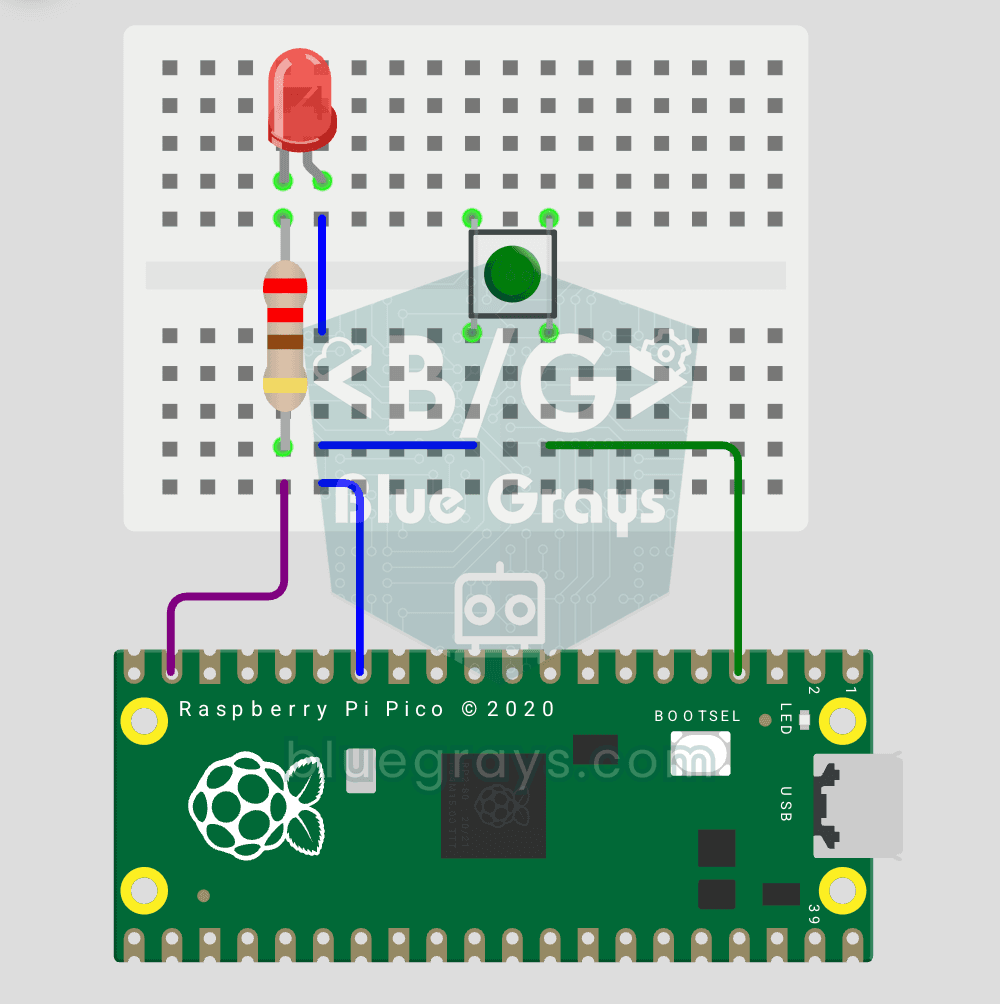
Button + LED — next level! Unlike the basic button project, there is no need to hold the button. Press and release → LED on. Press and release again → LED off (toggle). Same circuit (LED GP14, Button GP2), but big code difference. Learn edge detection (capturing the 1→0 falling moment), state tracking, debounce (mechanical bounce filter). MicroPython's led.toggle() swaps state in one line. Foundation of all interactive button projects (mode switcher, IRQ, double-click).
Lighting 220V Bulb with Button (On-Off)
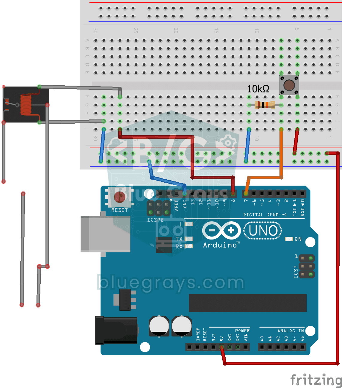
Want to switch a real household bulb on and off with a tiny button? Each time you press the button, the Arduino flips a relay and the bulb lights up; press again and it goes off. The relay is a go-bet
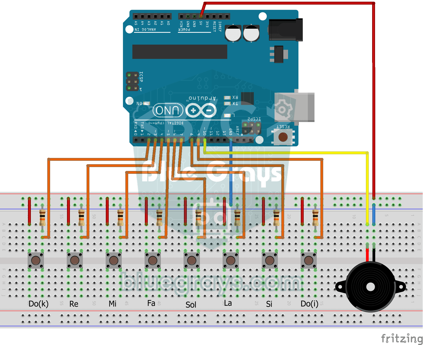
Simple Piano with Buzzer and Button
Build your own little piano with eight buttons. Each button is one note, from low to high: do, re, mi, fa, sol, la, ti and high do. The note plays through the buzzer as long as you hold the button and

ESP32 LED Fade with PWM
Smoothly changing the brightness of the LED from 0 to max, from max to 0. We control PWM with analogWrite() as in Arduino - the same syntax as ESP32 Arduino Core 3.0+ works without problems. Pin definition + pinMode + analogWrite is enough.

Smart Stair and Corridor Lighting
Step onto the stairs or into the hallway and the lights come on one step at a time in the direction you are walking. There is a distance sensor at each end; whichever one you pass, the eight LEDs ligh