
How to Use Fritzing: Breadboard Diagram Tutorial for Beginners
How do you use Fritzing? Install it, add parts, load .fzpz parts for ESP32 and Pico, use breadboard and schematic views, and export 300 dpi PNG files.
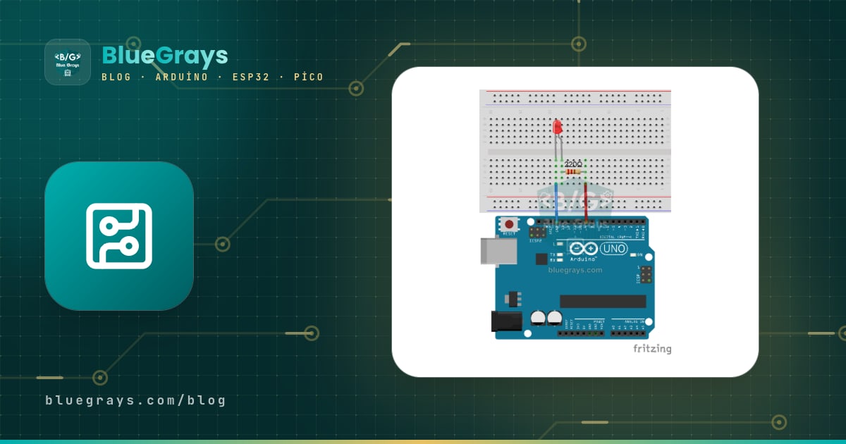
The short answer to "how do you use Fritzing": Fritzing is an open-source circuit design program where you draw your circuit by drag and drop as if you were building it on a real breadboard, then carry the same drawing over to schematic and PCB views. You pull parts from the Parts window on the right, join pins with wires, then export the drawing as PNG, SVG or PDF for your project report, presentation or poster. Most of the colourful breadboard drawings you see online in the Arduino world are made with Fritzing.
This guide starts with installing Fritzing and then walks you step by step through drawing an LED and button circuit with an Arduino Uno. You'll also learn how to load a .fzpz part file for boards missing from the library, such as the ESP32 and Raspberry Pi Pico, how to tidy a messy schematic, how to get a print-quality high-resolution image, and the rules for clean-looking drawings in a science fair report or poster.
What is Fritzing and how does it work?
Fritzing is a project started at the University of Applied Sciences Potsdam in Germany so that designers and students could document electronic prototypes easily. The program's key idea is keeping the same circuit in sync across different views. When you connect an LED to pin 9 of the Arduino in breadboard view, that connection also appears in schematic and PCB views as a dashed ratsnest line. So you make the connection once, and in the other views you only decide how to route it.
| View | What it shows | Best use |
|---|---|---|
| Breadboard | A realistic drawing of boards, parts and wires | Explaining the setup to beginners; images for reports and posters |
| Schematic | Standard circuit symbols and connection lines | Showing the logic of the circuit; technical explanation to a teacher or jury |
| PCB | Printed circuit board layout, copper traces and holes | Permanent board design, producing Gerber files |
| Simulator (1.0 and later) | Voltage and current values in simple DC circuits | Checking circuits with resistors, LEDs and batteries; it does not run Arduino code |
Installing Fritzing (Windows, macOS, Linux)
- Download the package for your operating system from the download page of the official Fritzing site. Current compiled releases are offered for a small fee that supports development; the source code is open.
- Windows: Run the installer, or unzip the package into a short folder (e.g. C:\Fritzing) and start Fritzing.exe. Avoid long folder paths and paths with special characters.
- macOS: Open the .dmg file and drag Fritzing into the Applications folder. If a security warning appears on first launch, right-click the app and choose Open.
- Linux: Give the AppImage file execute permission (chmod +x) and double-click to start it; on some distributions the program can also be installed from the package manager.
- On first launch, wait a few seconds while the parts database is prepared, then start a new drawing with New Sketch from the welcome screen.
- Menus are given by their English names in this post; you can change the interface language in the Preferences window, and the change applies after a restart.
Getting to know the interface
| Area | What it does |
|---|---|
| Tabs (Welcome, Breadboard, Schematic, PCB) | Let you switch between views |
| Parts | Parts library split into categories; use the magnifier icon to search |
| Inspector | Properties of the selected part: resistor value, LED colour, board model, breadboard size |
| Bottom toolbar | Buttons for rotate, flip, adding notes, autorouting and exporting |
| Status bar | Zoom level, and how many connections are not yet routed in schematic or PCB |
| Undo History | A list of everything you've done; go back to an earlier step with one click |
Your first circuit: drawing an LED and button with Arduino Uno
The fastest way to learn is to draw a real circuit. As an example we'll use an LED with a 220 Ω resistor and a push button: the LED lights when you press the button. You can check the resistor value with the LED resistor calculator; for a red LED with about a 2 V drop on a 5 V supply, aiming for 15 mA gives (5 − 2) / 0.015 = 200 Ω, and the next standard value up, 220 Ω, keeps the current at about 13.6 mA. The table below shows which pins the same circuit uses on three boards; the connection logic is the same whichever board you use in Fritzing.
| Connection | Arduino Uno | ESP32 | Raspberry Pi Pico |
|---|---|---|---|
| LED anode (through 220 Ω resistor) | D9 | GPIO 25 | GP15 |
| LED cathode | GND | GND | GND |
| One leg of the button | D2 | GPIO 26 | GP14 |
| Opposite leg of the button | GND | GND | GND |
- In the Parts window on the right, click the magnifier icon, type Arduino Uno and drag the Arduino Uno (Rev3) part next to the breadboard.
- From the CORE category, drop a Red LED, a Resistor and a Pushbutton onto the breadboard. To rotate a part, select it and press Ctrl+R (Cmd+R on macOS), or right-click and choose Rotate.
- Select the resistor and type 220Ω in the resistance field in the Inspector; the colour bands automatically become red-red-brown. If you like, compare with the resistor colour code tool.
- The bent leg of the LED drawing is the anode (+). Put the anode in the same row as one end of the resistor and the cathode on the breadboard's GND rail.
- Seat the button across the channel in the middle of the breadboard; that way opposite legs land in different rows and the button really works like a switch.
- To draw a wire, click the Arduino's D9 pin, drag, and release in the row where the other end of the resistor sits. In the same way, wire D2 to one leg of the button, and wire the opposite leg of the button and the Arduino's GND pin to the breadboard's GND rail.
- Make sure the wire ends are green; a red end means the wire isn't seated in any pin.
- Save the drawing with File > Save as a .fzz file. This file keeps the whole project in a single package, including the custom parts you used.
After finishing the drawing, build the real circuit and test it with the code below. The pin numbers in Fritzing and in the code must match; that's how you prove the drawing in your report is correct. If you use an ESP32, just set LED_PIN to 25 and BUTTON_PIN to 26.
1// Fritzing'de çizdiğin devreyi test et / Test the circuit you drew in Fritzing
2const int LED_PIN = 9;     // LED, 220 ohm üzerinden D9'a (ESP32: 25) / LED to D9 via 220 ohm (ESP32: 25)
3const int BUTTON_PIN = 2;  // buton D2 ile GND arasında (ESP32: 26) / button between D2 and GND (ESP32: 26)
4
5bool lastPressed = false;
6
7void setup() {
8  pinMode(LED_PIN, OUTPUT);
9  pinMode(BUTTON_PIN, INPUT_PULLUP);  // dahili pull-up direnci / internal pull-up resistor
10  Serial.begin(115200);
11}
12
13void loop() {
14  bool pressed = (digitalRead(BUTTON_PIN) == LOW);  // basılıyken LOW okunur / reads LOW while pressed
15  digitalWrite(LED_PIN, pressed ? HIGH : LOW);
16  if (pressed != lastPressed) {                       // durum değişti mi? / did the state change?
17    Serial.println(pressed ? "Buton basildi / Button pressed" : "Buton birakildi / Button released");
18    lastPressed = pressed;
19  }
20  delay(10);                                          // basit debounce / simple debounce
21}
We didn't add an external resistor for the button, because INPUT_PULLUP enables the Arduino Uno's internal resistor of roughly 20–50 kΩ; the pin reads HIGH when the button is released and LOW when pressed, since it's pulled to GND. That's why in the Fritzing drawing one leg of the button goes straight to GND. If you want the details, see the post on pull-up and pull-down resistors.
If you drew the same circuit with a Raspberry Pi Pico, the LED is on GP15 and the button on GP14. The MicroPython test code looks like this:
1from machine import Pin
2import time
3
4led = Pin(15, Pin.OUT)                   # LED 220 ohm üzerinden GP15'e / LED to GP15 via 220 ohm
5button = Pin(14, Pin.IN, Pin.PULL_UP)    # buton GP14 ile GND arasında / button between GP14 and GND
6
7while True:
8    led.value(1 if button.value() == 0 else 0)   # basılıyken yak / on while pressed
9    time.sleep_ms(10)                            # basit debounce / simple debounce
Loading missing parts: .fzpz for ESP32 and Raspberry Pi Pico
Fritzing's core library is rich in Arduino boards, sensors and basic parts, but it doesn't include every development board; in older versions in particular the ESP32 DevKit or Raspberry Pi Pico may be missing. In that case you load the part from outside as a package with a .fzpz extension. This package is a compressed file containing the part's breadboard, schematic and PCB drawings (SVG) and its pin definitions. Raspberry Pi publishes an official Fritzing part for the Pico; manufacturers such as Adafruit and SparkFun also share parts for their own modules. For the ESP32, 30-pin and 38-pin DevKit boards have separate parts; count the pins on your board and choose the right file. For basic information about the boards, see What is ESP32.
- Download the part file from a trusted source; if it came inside a .zip, extract the archive first and take out the .fzpz file.
- In Fritzing, click the menu button in the Parts window and choose Import.... Alternatively, you can open the .fzpz file directly with File > Open.
- The imported part appears in the MINE bin (my parts); drag it into breadboard view from there.
- Hover the mouse over a few pins of the board; the tooltip shows the pin name (e.g. GPIO25 or GP15). Compare these names with the labels on the real board.
- Switch to schematic view and make sure the part's symbol has come through too; some community parts have a proper drawing only in breadboard view.
- When you close the program and it asks whether to save the MINE bin, confirm; that way the part stays in your library the next time you open it.
| Extension | Contents | When to use |
|---|---|---|
| .fzz | Project package: the drawing and the custom parts used in it | Always use this for sharing and submitting |
| .fz | Drawing file only (XML), without custom parts | May show a missing-part warning when opened on another computer |
| .fzpz | Package for a single part (SVG drawings and pin definition) | Added to the library with Import |
| .fzbz | Parts bin package: several parts | For sharing the same set of parts across a class |
Schematic view: from messy lines to a readable diagram
When you finish drawing in breadboard view and switch to the Schematic tab, you'll see the parts piled on top of each other with dashed lines between them. These dashed lines are connections you made on the breadboard but haven't yet drawn in the schematic. First drag the parts into a sensible layout: Arduino in the middle, inputs (button, sensor) on the left, outputs (LED, buzzer) on the right. Then double-click a ratsnest line to create a real trace, or drag from a pin to draw one yourself. The status bar at the bottom shows how many connections are still unrouted; the schematic isn't complete until that number reaches zero. The Routing > Autoroute command does the job automatically, but the result is usually messy, so drawing by hand looks much cleaner for small circuits.
Exporting as PNG, SVG and PDF
| Format | Where to use it | Tip |
|---|---|---|
| PNG | Word or Google Docs report, presentation slide | Choose 300 dpi; it prints sharp on an A4 page |
| SVG | Poster, banner, large print | It's a vector, so it scales to any size with no quality loss |
| Printing and file submission | Gives a clean output for schematic view | |
| JPG | If there's no other option | Compression blurs wire edges, so prefer PNG |
| List of parts (BOM) | The bill of materials for your report | Gives all the parts used as an HTML table |
| Extended Gerber | PCB manufacturing | Only meaningful in PCB view |
- Switch to the tab of the view you want to export; Fritzing only saves the view that is currently open.
- Use View > Fit in Window to fit the whole circuit on screen and delete unused parts; even a single forgotten part widens the edges of the image.
- Choose File > Export > as Image > PNG... and give the file a name without special characters (e.g. led-button-breadboard.png).
- Enter 300 dpi as the resolution. If you'll only share it on screen, 150 dpi is enough; 600 dpi needlessly enlarges the file.
- For a poster, save an SVG from the same menu; for the parts list, choose File > Export > List of parts (Bill of Materials) and add the resulting table to your report.
Tips for clean drawings in project reports and posters
- Standardise wire colours: use red for 5 V, orange for 3.3 V, black for GND, and yellow, green or blue for signals. Right-click a wire and use the Wire Color menu to change its colour.
- Bend wires at 90-degree angles: when you grab a wire in the middle and drag, a bend point is created; neat corners instead of diagonal wires greatly improve readability. You can delete an unnecessary bend point by double-clicking it.
- Don't route wires over parts: a wire that falls over the labels on a board or module stops the reader from seeing the pin name.
- Add labels and notes: right-click a part and use Show part label to make a resistor's value or a sensor's name visible, and write short explanations with Edit > Add Note.
- Choose the breadboard size to suit the circuit: picking a half-size breadboard from the Inspector for small circuits avoids leaving needless empty space in the image. For the internal connections of a real breadboard, see how to use a breadboard.
- Provide the breadboard and the schematic together: if your report has the breadboard image on top and the schematic and pin table below, both a beginner and a technical jury will understand your circuit. For report layout see writing a TÜBİTAK project report, and for presenting see science fair project presentation.
- Think about scale on a poster: on a 70×100 cm poster the circuit should be printed at least 30 cm wide; for that, use SVG or export the PNG at 300 dpi with a width of at least 3500 pixels.
Fritzing vs Tinkercad vs Wokwi
| Feature | Fritzing | Tinkercad Circuits | Wokwi |
|---|---|---|---|
| How it runs | Program installed on your computer | In the browser, account required | In the browser |
| Breadboard drawing | Very realistic, wide parts support | Yes, limited parts | Yes, plain look |
| Schematic and PCB | Both available | Schematic yes, PCB no | No |
| Arduino code simulation | No | Yes (Arduino Uno and micro:bit) | Yes |
| ESP32 and Pico | With an extra .fzpz part | No | Yes |
| Best at | Reports, posters, PCBs | First Arduino lessons at school | Trying code without hardware |
In practice these tools complement each other rather than compete: you try the code in Wokwi or Tinkercad, then prepare a clean image of the working circuit with Fritzing. When you want to make your circuit permanent, you can use Fritzing's PCB view or PCB design with EasyEDA.
Common mistakes and how to fix them
| Problem | Cause | Fix |
|---|---|---|
| Wire end is red | The wire isn't seated in a pin or hole | Drag the end onto the pin and wait for it to turn green |
| Connection missing in the schematic | The part's leg isn't seated in a breadboard hole | In breadboard view, move the part slightly and place it again |
| Part missing or a grey box in an opened file | A custom part was moved with the .fz file or isn't in the library | Save the project as .fzz and import the missing .fzpz file |
| PNG is blurry | Low resolution or JPG was chosen | Choose PNG and 300 dpi, and don't compress the image when adding it to the report |
| Lots of empty space around the circuit in the image | A forgotten part or note in the drawing area | Check with Fit in Window and delete the extras |
| The program has slowed down | A very large breadboard and hundreds of wires | Delete unneeded parts, or split the circuit into sections and draw them separately |
After drawing a few circuits with Fritzing, placing parts and arranging wires becomes a matter of minutes. For practice, start with simple circuits: draw projects such as lighting an LED, a traffic light and button-controlled LED in Fritzing first, then build them on a real breadboard. In the BlueGrays app you can find each of these projects for Arduino, ESP32 and Raspberry Pi Pico with a step-by-step circuit diagram and ready code, and compare your own drawing with those diagrams.
Frequently asked questions
Is Fritzing free?
Fritzing is an open-source project and its source code is available to everyone. The current compiled releases on the official site are downloaded for a small fee to support development. In the package repositories of some Linux distributions the program can be found for free.
How do you add an ESP32 to Fritzing?
Download the .fzpz part file for your ESP32 DevKit board and import it with Import... from the menu in the Parts window. The part appears in the MINE bin and you drag it onto the breadboard from there. 30-pin and 38-pin boards differ, so choose the part with the same pin count as your board.
Can you simulate circuits in Fritzing?
Newer versions include a built-in simulator that shows voltage and current in simple DC circuits made of parts such as resistors, LEDs, batteries and potentiometers. However, Fritzing does not run Arduino code. For simulation with code, you need to use Wokwi or Tinkercad Circuits.
How do you save a Fritzing drawing as an image?
Switch to the tab of the view you want to save and choose PNG, SVG, JPG or PDF from File > Export > as Image. A 300 dpi PNG gives the best result for a report and SVG for a poster. Fritzing only exports the view that is currently open.
Why do parts disappear when a Fritzing file is opened on another computer?
Parts you import from outside are stored only in your own library. If you save the project in .fzz format, these parts are packaged inside the file and appear on the other computer too. Opening a file saved with a much newer version in an older version can also cause missing parts.
Can you design and manufacture a PCB with Fritzing?
Yes. In PCB view you place the parts on the board and draw the copper traces by hand or with Autoroute. Then you can export Extended Gerber files from File > Export > for Production and send them to a PCB manufacturer. For complex multilayer boards, KiCad or EasyEDA are more suitable tools.
Projects to build after reading this
See all projects
LED Blink
The very first hello of electronics: switching a single LED on and off. The Arduino turns the LED on and off at short intervals, so the light blinks quickly.

Traffic Light
A tiny copy of the traffic light you see on the road every day. Red stays on for two seconds, yellow flashes for a moment, green stays on for two seconds, then it goes back to red through yellow…

LED Control with a Push Button (Push)
Just like a doorbell: the light stays on as long as you press, and goes off when you let go.

Toggle an LED with a Button (On/Off)
Press the button once and the light comes on, press it again and it goes off, just like the light switch in your room.

Night Light with Ldr
A little night light that turns on by itself when it gets dark and goes off when morning comes.

LED Blink with ESP32
Teaches basic GPIO output usage with ESP32. We achieve a blinking effect by turning an LED on and off from a digital pin. ESP32 version of the classic blink project on Arduino UNO; the basic blink commands in the Arduino environment are the same, but the ESP32's pin layout and 3.3 V GPIO levels differ from those of the Arduino UNO.

ESP32 LED Control with Push Button (Push)
The LED lights up when the button is pressed and turns off when released. Shows how the ESP32's digital input pin and internal pull-up resistor are used. The INPUT_PULLUP mode eliminates the need for an external resistor.
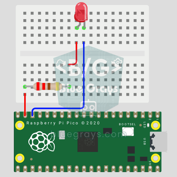
Raspberry Pi Pico: Controlling an External LED (Breadboard)
The next step after the Pico's built-in LED: connect an external LED on a breadboard and control it through pin GP14. You'll learn how to use any of the Pico's GPIO pins as an output, the LED's polarity (long leg = anode/+, short leg = cathode/–) and why a current-limiting resistor (220Ω) is a must. Without the resistor, too much current flows through the LED and it can burn out.