
Wokwi Simulator Tutorial: Run ESP32, Arduino and Pico Online
Wokwi simulator for ESP32, Arduino and Pico: wiring with diagram.json, Wi-Fi, MicroPython, the logic analyzer, the VS Code extension and how it beats Tinkercad.

The Wokwi simulator is a free electronics simulator that lets you run ESP32, Arduino and Raspberry Pi Pico projects in your browser without buying a single part. You write your code, place LEDs, buttons, displays and sensors next to the virtual board and press the green play button: the code compiles, the LED lights up, text appears on the OLED and the Serial Monitor starts scrolling. Its biggest difference from Tinkercad is support for the ESP32 and Pico; you can even take the ESP32 onto the real internet through a virtual Wi-Fi network and run MicroPython on the Pico.
In this guide you'll start by opening your first project on wokwi.com, then learn to wire parts with the mouse and with the diagram.json file, add libraries, try Wi-Fi and internet time on an ESP32, run MicroPython on a Pico, measure a PWM signal with the logic analyzer and use the same simulation inside VS Code. At the end you'll see which sensors are supported, where the simulation differs from a real circuit and how to share your project.
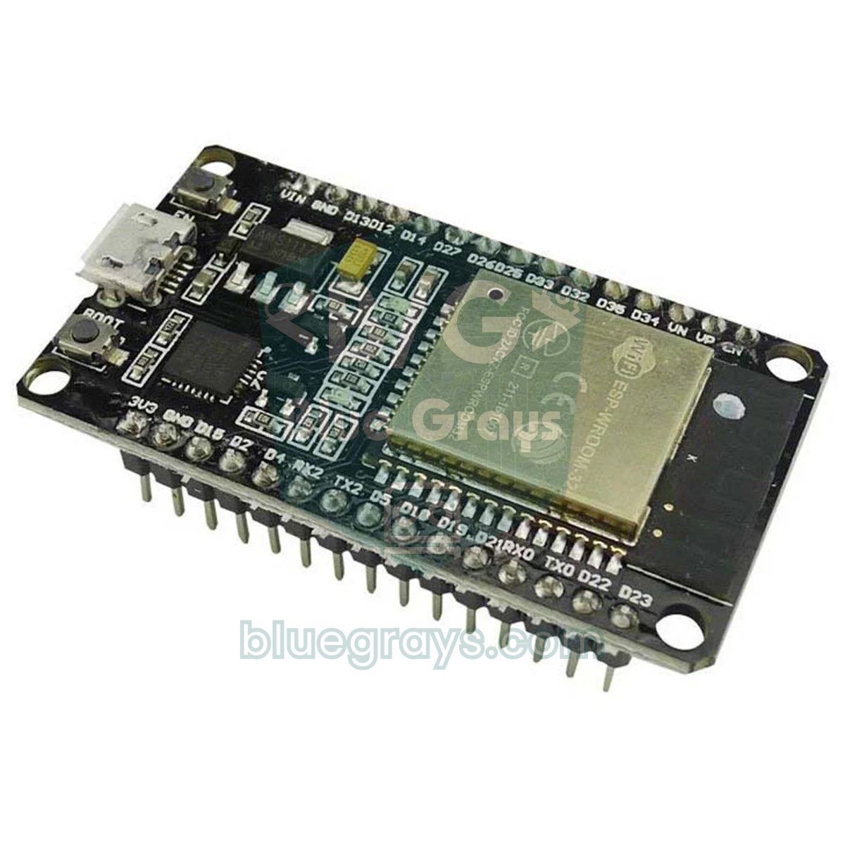
What is Wokwi and how does it work?
Wokwi compiles your code in the cloud with real compilers and hands the resulting machine code to a processor emulator running in your browser. So in an Arduino Uno simulation the ATmega328P instructions are executed one by one, and the same approach applies to the ESP32 and RP2040. That's why hardware features such as millis(), interrupts, timers, PWM, I2C and SPI behave as they do on the real board, and real libraries run without changes. Wokwi doesn't calculate the currents and voltages in your circuit; it models the digital levels of the pins and the values fed to the analog inputs. This design makes it a powerful tool for trying out embedded software rather than electronics fundamentals.
| Feature | Wokwi |
|---|---|
| Where it runs | Browser (wokwi.com) and VS Code extension |
| Boards | Arduino Uno, Nano, Mega; ESP32, ESP32-S3, ESP32-C3; Raspberry Pi Pico and Pico W |
| Languages | Arduino C++, MicroPython, CircuitPython (Pico), ESP-IDF |
| Libraries | Most libraries in the Arduino Library Manager (libraries.txt) |
| Network | Virtual Wi-Fi for ESP32 and Pico W: Wokwi-GUEST |
| Measurement tool | 8-channel logic analyzer; no electrical measurements |
| Account | Not needed to try it, sign in to save a project |
| Price | Basic use is free; extra features are on a paid plan |
Which boards does Wokwi support?
Every part in Wokwi has a type name, which you'll see in the diagram.json file. The table below shows the Wokwi equivalents of the three platforms this blog focuses on. In older projects you may also see wokwi-esp32-devkit-v1 for the ESP32; both simulate the same ESP32 chip, only the board's pin layout differs.
| Board | Wokwi type name | Language options | Note |
|---|---|---|---|
| Arduino Uno | wokwi-arduino-uno | Arduino C++ | ATmega328P, 5 V logic, fastest simulation |
| Arduino Nano | wokwi-arduino-nano | Arduino C++ | Same chip as the Uno, smaller board |
| Arduino Mega | wokwi-arduino-mega | Arduino C++ | 8 KB SRAM, projects with many pins |
| ESP32 DevKit | board-esp32-devkit-c-v4 | Arduino C++, MicroPython, ESP-IDF | Wi-Fi yes, Bluetooth no |
| ESP32-S3 / ESP32-C3 | board-esp32-s3-devkitc-1 / board-esp32-c3-devkitm-1 | Arduino C++, MicroPython, ESP-IDF | Newer ESP32 families |
| Raspberry Pi Pico | wokwi-pi-pico | MicroPython, CircuitPython, Arduino C++ | RP2040, 3.3 V logic |
| Raspberry Pi Pico W | board-pi-pico-w | MicroPython, Arduino C++ | With Wi-Fi |
Your first Wokwi project in the browser, step by step
- Open wokwi.com in your browser. The home page has Arduino, ESP32 and Raspberry Pi Pico sections; pick one to see ready-made templates and example projects.
- For a blank start, choose the Arduino Uno template under Arduino. The screen splits in two: the code editor (sketch.ino) on the left and the diagram area where the circuit is drawn on the right.
- Press the blue + button above the right-hand area and type LED in the search box. The part you choose drops near the board; drag it with the mouse to where you want it.
- Add a Resistor and a Pushbutton the same way. Clicking a part opens a small panel where you can change its colour or value; set the resistor to 220 Ω.
- To draw a wire, click the end of a pin, then click the pin it should connect to. Click an empty spot in between to bend the wire's path. Click a wire to change its colour or delete it with the Delete key.
- Type your code on the left or paste the example below, then press the green play button. The first build takes a few seconds; then the simulation starts and, if you use Serial.begin, the Serial Monitor opens at the bottom.
- While the simulation runs, click the button with the mouse. Press the square button to stop. To keep the project, press Save; the first time you'll be asked to sign in and your project gets a permanent link.
First circuit: toggle an LED with a button
You can build the classic first experiment, a button and an LED, with the same logic on all three boards. The LED's long leg (anode, A in Wokwi) goes through the resistor to the output pin and the short leg (cathode, C) goes to GND. One side of the button connects to the input pin and the other to GND; the code turns on the internal pull-up resistor. To calculate the LED resistor for your own circuit you can use the LED resistor calculator.
| Connection | Arduino Uno | ESP32 | Raspberry Pi Pico |
|---|---|---|---|
| LED anode (A), through a 220 Ω resistor | D13 | GPIO 18 | GP14 |
| LED cathode (C) | GND | GND | GND |
| Button leg 1 | D2 | GPIO 4 | GP2 |
| Button leg 2 | GND | GND | GND |
| Logic level | 5 V | 3.3 V | 3.3 V |
1// Wokwi ilk proje: buton ile LED aç/kapat / Wokwi first project: toggle an LED with a button
2const int LED_PIN = 13;     // ESP32'de 18 / 18 on ESP32
3const int BUTON_PIN = 2;    // ESP32'de 4, diğer uç GND / 4 on ESP32, other leg to GND
4
5bool ledDurum = false;           // LED durumu / LED state
6bool oncekiOkuma = HIGH;         // önceki buton okuması / previous button reading
7unsigned long sonDegisim = 0;    // son kabul edilen değişim / last accepted change
8
9void setup() {
10  pinMode(LED_PIN, OUTPUT);
11  pinMode(BUTON_PIN, INPUT_PULLUP);   // dahili pull-up: basılınca LOW / internal pull-up: LOW when pressed
12  Serial.begin(115200);
13  Serial.println("Wokwi hazir / ready");
14}
15
16void loop() {
17  bool okuma = digitalRead(BUTON_PIN);
18  if (okuma != oncekiOkuma && millis() - sonDegisim > 50) {   // 50 ms debounce
19    sonDegisim = millis();
20    oncekiOkuma = okuma;
21    if (okuma == LOW) {                                       // basıldı / pressed
22      ledDurum = !ledDurum;
23      digitalWrite(LED_PIN, ledDurum ? HIGH : LOW);
24      Serial.print("LED: ");
25      Serial.println(ledDurum ? "ACIK / ON" : "KAPALI / OFF");
26    }
27  }
28}
The Wokwi button bounces like a real one: on a single press the contact opens and closes for a few milliseconds. That's why the code waits 50 ms; delete it and you'll sometimes see the LED toggle twice. It's a nice detail that makes what you learn in the simulation useful in a real circuit too. You'll find the timing logic explained in detail in the millis vs delay article.
diagram.json: wiring parts with a file
Everything you draw with the mouse is actually written to the project's diagram.json file. You can open it from the tabs above the code editor, edit it by hand or copy it into another project. The file has three important sections: parts (the parts, their types, positions and settings), connections (the wires) and the optional dependencies. Here is the diagram.json file for the Uno circuit above:
1{
2  "version": 1,
3  "author": "BlueGrays",
4  "editor": "wokwi",
5  "parts": [
6    { "type": "wokwi-arduino-uno", "id": "uno", "top": 0, "left": 0, "attrs": {} },
7    { "type": "wokwi-led", "id": "led1", "top": -96, "left": 172, "attrs": { "color": "red" } },
8    { "type": "wokwi-resistor", "id": "r1", "top": -24, "left": 120, "rotate": 90, "attrs": { "value": "220" } },
9    { "type": "wokwi-pushbutton", "id": "btn1", "top": -110, "left": 260, "attrs": { "color": "green", "bounce": "1" } }
10  ],
11  "connections": [
12    [ "uno:13", "r1:1", "green", [] ],
13    [ "r1:2", "led1:A", "green", [] ],
14    [ "led1:C", "uno:GND.1", "black", [] ],
15    [ "uno:2", "btn1:1.l", "blue", [] ],
16    [ "btn1:2.l", "uno:GND.2", "black", [] ]
17  ],
18  "dependencies": {}
19}| Field | What does it do? | Example |
|---|---|---|
| type | The part's type | wokwi-led, wokwi-dht22, board-ssd1306 |
| id | The part's name; wires use this name | led1, uno, esp |
| top / left / rotate | Position on screen (pixels) and rotation angle | "rotate": 90 |
| attrs | Part-specific settings | "color": "red", "value": "220" |
| connections | Each wire: [start pin, end pin, colour, path] | ["uno:13", "r1:1", "green", []] |
| Pin name format | part-id:pin-name | uno:GND.1, esp:18, pico:GP14, btn1:1.l |
The easiest way to learn pin names is to hover over a pin in the diagram area; Wokwi shows the pin's name in a small label. The button's four legs are named 1.l, 2.l, 1.r, 2.r: legs with the same number are connected inside, and pressing joins 1 and 2. Set the button's bounce attribute to "0" to switch bouncing off; give its key attribute a value such as "1" and you can press it from the keyboard too. In large circuits, editing diagram.json by hand is much faster than drawing dozens of wires one by one.
Adding libraries: libraries.txt
To install an Arduino library in Wokwi, open the Library Manager tab above the code editor, press the + button and search for the library's name. The library you pick is added as a line to the project's libraries.txt file and installed automatically in the cloud during the build. You can also write the file by hand; each line holds one library, named as it appears in the Arduino Library Manager:
1# Wokwi Library List
2Adafruit SSD1306
3Adafruit GFX Library
4DHT sensor library
5Adafruit NeoPixelInteracting with sensors: changing values during the simulation
The most instructive thing about Wokwi is that you can set sensor values with the mouse. While the simulation runs, click the DHT22 to open temperature and humidity sliders; click the HC-SR04 to pick a distance between 2 and 400 cm. The PIR sensor has a button that simulates motion, the potentiometer has a knob you can turn and the LDR module has a light intensity (lux) slider. This lets you test a condition like "turn on the fan when the temperature passes 30 °C" in seconds and verify the thresholds in your code without owning the real sensor.
Wi-Fi simulation with the ESP32
The ESP32 in Wokwi connects to a virtual access point called Wokwi-GUEST. This network has no password and runs on channel 6; specifying the channel speeds up the connection. The network reaches the real internet through Wokwi's gateway: you can get the time from NTP, send HTTP requests to a server or publish data to an MQTT broker. The code below connects the ESP32, prints its IP address and fetches the Istanbul time from the internet.
1#include <WiFi.h>
2#include <time.h>
3
4void setup() {
5  Serial.begin(115200);
6  WiFi.begin("Wokwi-GUEST", "", 6);          // Wokwi sanal ağı: şifresiz, kanal 6 / Wokwi virtual network: open, channel 6
7  Serial.print("Baglaniyor / Connecting");
8  while (WiFi.status() != WL_CONNECTED) {
9    delay(250);
10    Serial.print(".");
11  }
12  Serial.println();
13  Serial.print("IP: ");
14  Serial.println(WiFi.localIP());
15  configTime(3 * 3600, 0, "pool.ntp.org");   // UTC+3 İstanbul, yaz saati yok / UTC+3 Istanbul, no DST
16}
17
18void loop() {
19  struct tm zaman;                            // saat bilgisi / time info
20  if (getLocalTime(&zaman)) {
21    Serial.printf("%02d:%02d:%02d\n", zaman.tm_hour, zaman.tm_min, zaman.tm_sec);
22  } else {
23    Serial.println("Saat alinamadi / Time not ready");
24  }
25  delay(1000);
26}
When you use this code on a real ESP32, just type your network name and password; you can remove the channel parameter. On the free tier the ESP32 can connect out to the internet, but the browser on your computer can't reach a web server running inside the ESP32 directly. For that you need the port forwarding in the VS Code extension or the private gateway on the paid plan. For NTP and time zone details see ESP32 NTP time, and for connection problems on a real board see ESP32 won't connect to Wi-Fi.
Raspberry Pi Pico and MicroPython support
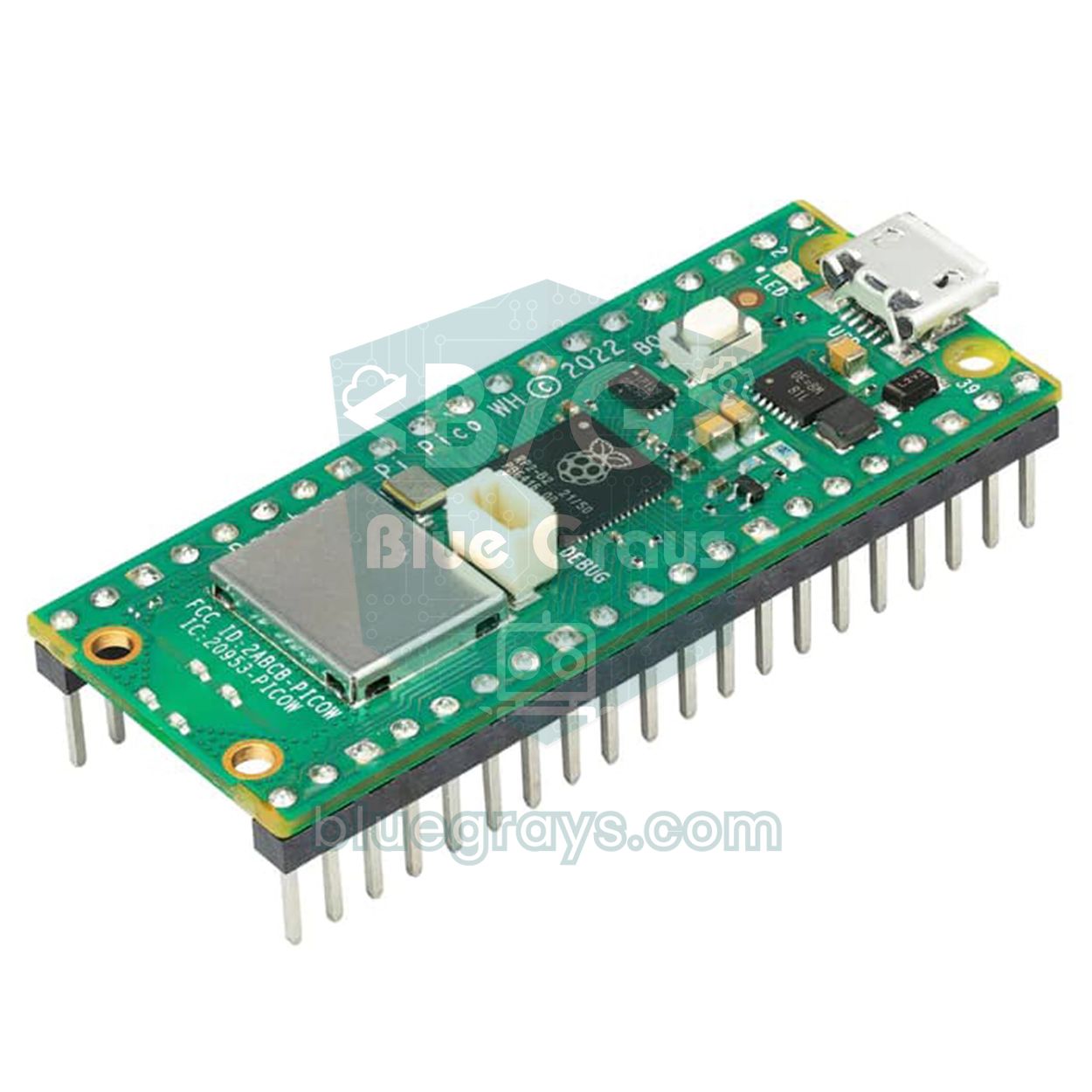
When you choose the MicroPython template for the Pico on the home page, the project opens with a main.py file. Press play and the MicroPython interpreter loads, main.py runs and you see the print output in the console below. When the program ends, the same console drops into the REPL, where you can type commands and experiment instantly. If you need extra modules such as the SSD1306 driver, create a new file from the file menu and paste the module's contents. The same applies to the ESP32: just choose the MicroPython template in the ESP32 section.
1from machine import Pin, ADC
2import time
3
4led = Pin(14, Pin.OUT)                  # LED + 220 ohm direnç / LED + 220 ohm resistor
5buton = Pin(2, Pin.IN, Pin.PULL_UP)     # diğer uç GND / other leg to GND
6pot = ADC(26)                           # potansiyometre orta ucu GP26 / pot wiper on GP26
7
8durum = False
9onceki = 1
10son = time.ticks_ms()                   # son pot yazdırma zamanı / last pot print time
11while True:
12    okuma = buton.value()
13    if okuma == 0 and onceki == 1:      # yeni basış / new press
14        durum = not durum
15        led.value(durum)
16        print("LED:", "ACIK" if durum else "KAPALI")
17        time.sleep_ms(50)               # debounce
18    onceki = okuma
19    if time.ticks_diff(time.ticks_ms(), son) >= 500:
20        son = time.ticks_ms()
21        gerilim = pot.read_u16() * 3.3 / 65535   # 16 bit okuma -> volt / 16-bit reading -> volts
22        print("Pot: {:.2f} V".format(gerilim))
23    time.sleep_ms(10)
In the code the LED is on GP14, the button on GP2 and the potentiometer wiper on GP26 (ADC0); the potentiometer's outer legs go to 3V3 and GND. The Pico's ADC is 12-bit, but MicroPython's read_u16() returns a value scaled to 0–65535. If you're new to MicroPython, the MicroPython basics article explains the Pin, ADC, PWM and timing commands one by one.
Seeing signals with the logic analyzer
Wokwi has no multimeter, but it has a far more powerful tool: the Logic Analyzer. Add it from the parts list and it records 8 digital channels (D0–D7). Connect the channels to the pins you want to measure and its GND to the board's GND. When you stop the simulation, the recording downloads as a .vcd file; open it in free programs such as PulseView or GTKWave to read the signal's frequency and pulse width, and even decode UART, I2C or SPI bytes.
1// Mantık analizörü D0 -> Uno D9, D1 -> Uno D1 (TX), GND -> GND
2// Logic analyzer D0 -> Uno D9, D1 -> Uno D1 (TX), GND -> GND
3void setup() {
4  Serial.begin(9600);
5  analogWrite(9, 64);            // %25 doluluk, yaklaşık 490 Hz / 25% duty, about 490 Hz
6}
7
8void loop() {
9  Serial.write('A');             // TX hattında çözülecek bayt / byte to decode on the TX line
10  delay(100);
11}
When you open the recording, channel D0 shows a square wave with a period of about 2.04 ms (490 Hz); the pulse stays high for a quarter of the period, about 0.51 ms. That's because analogWrite(9, 64) corresponds to a duty cycle of 64/255 ≈ 25%. On the Uno, pins 5 and 6 produce 980 Hz and the other PWM pins 490 Hz; you can verify this yourself with the analyzer. Add a UART decoder to channel D1 in PulseView and you'll read the byte 0x41 (A) every 100 ms. For how PWM works, see What is PWM?.
The Wokwi VS Code extension
For larger projects, if you'd rather use your own editor than the browser, you can install the Wokwi Simulator extension in VS Code. The extension doesn't compile your code; it simulates the firmware file you build with PlatformIO, ESP-IDF or arduino-cli. Personal use runs on a free licence that you renew at regular intervals. Setup takes these steps:
- In VS Code, search for Wokwi Simulator in the Extensions view and install it.
- Open the command palette with F1, run Wokwi: Request a New License and confirm the licence on the page that opens in your browser.
- Add a wokwi.toml file and a diagram.json file to the root of your project folder. You can copy diagram.json from a project you drew in the browser.
- Build the project as usual (Build in PlatformIO). The paths in wokwi.toml must point to the compiled .bin and .elf files.
- Press F1 and run Wokwi: Start Simulator. The simulation opens in a VS Code tab; when you change the code and rebuild, the simulation restarts.
1# wokwi.toml (PlatformIO, esp32dev ortamı / environment)
2[wokwi]
3version = 1
4firmware = ".pio/build/esp32dev/firmware.bin"
5elf = ".pio/build/esp32dev/firmware.elf"
6
7# ESP32 web sunucusunu bilgisayardan açmak: http://localhost:8180
8# Open the ESP32 web server from your computer: http://localhost:8180
9[[net.forward]]
10from = "localhost:8180"
11to = "target:80"
The net.forward section here forwards the web server on the ESP32's port 80 to port 8180 on your computer. That way you can open projects such as the ESP32 web server and WebSocket in your own browser without flashing a board. The extension also supports step-by-step debugging with GDB; add a gdbServerPort line to wokwi.toml and attach VS Code's debugger.
Differences between Wokwi and Tinkercad
Both simulators are free and run in the browser, but they answer different questions. Tinkercad calculates the circuit electrically: you can measure the current through a resistor or the voltage across an LED with a multimeter, and it supports block code. Wokwi emulates the board's processor and offers the ESP32, Pico, Wi-Fi, MicroPython and broad library support. Starting electronics fundamentals in Tinkercad and ESP32 and IoT projects in Wokwi is the most efficient path. To get to know Tinkercad in detail, see the Tinkercad Arduino simulator guide.
| Feature | Wokwi | Tinkercad Circuits |
|---|---|---|
| Boards | Uno, Nano, Mega, ESP32 family, Pico, Pico W | Arduino Uno R3, ATtiny, micro:bit |
| Electrical calculation | None; digital levels and an analog value model | Yes; multimeter and oscilloscope |
| Wi-Fi and internet | Yes, with ESP32 and Pico W | No |
| MicroPython | Yes, on Pico and ESP32 | No |
| Libraries | Most of those in the Library Manager | About eleven built-in libraries |
| Block code | No | Yes |
| Circuit file | diagram.json, editable by hand | Visual editor only |
| Measurement | Logic analyzer (.vcd) | Multimeter, oscilloscope |
| Desktop | VS Code extension | No |
Supported sensors and modules
| Group | Available in Wokwi | Missing or limited |
|---|---|---|
| Light and displays | LED, RGB LED, NeoPixel strip and ring, 16x2 and 20x4 LCD (including I2C), SSD1306 OLED, ILI9341 TFT, MAX7219 matrix, TM1637, 7-segment | E-paper and most colour OLEDs |
| Input | Button, switch, DIP switch, potentiometer, rotary encoder (KY-040), joystick, membrane keypad, IR receiver and remote | Touch screen |
| Sensors | DHT22, DS18B20, HC-SR04, PIR, MPU6050, LDR module, NTC module, HX711 and load cell, MQ-2 gas, flame, sound, tilt | DHT11 (use DHT22), colour and fingerprint sensors |
| Motion | Servo, stepper motor, A4988 driver, relay module, buzzer | DC motor and motor drivers such as the L298N |
| Communication and storage | DS1307 RTC, microSD card, 74HC595, I2C, SPI, UART | RC522 RFID, nRF24L01, HC-05, SIM800L, GPS |
| Analog circuits | Potentiometer and analog sensor modules | Real analog calculation of transistors, op-amps, capacitors |
For a part that isn't on the list you have two options. The first is to use a part that behaves similarly; for example, you test DHT11 code with the DHT22 part. The second is the Custom Chips feature: a small program you write in C is compiled to WebAssembly and added to the circuit as a new part with its own pins. This way you can model a simple I2C sensor or a module that talks over UART yourself.
Limits of the simulation: how it differs from a real circuit
- No electrical calculation: An LED wired without a resistor keeps glowing, and feeding 5 V into an ESP32 pin burns nothing. In a real circuit both cost you parts. Calculate current and voltage yourself with Ohm's law.
- Speed: The indicator in the corner of the diagram area shows the simulation's speed as a percentage of real time. ESP32 projects that use Wi-Fi or have many parts may run slower than real time; keep this in mind in code that measures durations.
- Ideal sensors: Virtual sensors are noise-free and need no calibration. A real DHT22 is off by ±0.5 °C and an HC-SR04 misreads soft surfaces; write filtering and error checks anyway.
- No power or battery: Current draw, voltage drop, regulator heating and brownouts don't show up in the simulation.
- No Bluetooth: The ESP32's BLE and classic Bluetooth features aren't simulated.
- Wiring mistakes: Real-life problems such as a loose jumper, a wrong breadboard row or a cold solder joint don't exist; a circuit that works in the simulation may not work on the first try in reality.
Sharing a project and moving it to a real board
Every project you save gets a permanent address; use the Share button to copy the link and send it to a friend, a teacher or a forum. Whoever opens the link runs the project with one click and can copy it to their own account to make changes. That makes Wokwi the fastest way to show your circuit and code together when you ask for help with "my code doesn't work". From the menu next to the Save button you can download the project as a zip file containing sketch.ino, diagram.json and libraries.txt.
- Paste the code that works in the simulation into a new sketch in the Arduino IDE, or open sketch.ino from the zip you downloaded.
- Install every library in libraries.txt from the Arduino IDE's Library Manager.
- In Wi-Fi code, replace Wokwi-GUEST with your own network name and password.
- Turn the connections in diagram.json into a pin table and build the circuit on a breadboard from that table. Don't forget to add resistors Wokwi didn't need (LED resistor, I2C pull-ups).
- Select the board and the port and upload. If something goes wrong, follow the steps in the Arduino code won't upload guide.
Project ideas to try in Wokwi
- Weather station with OLED: Show temperature and humidity on screen with an ESP32, a DHT22 and an SSD1306; change the values with the sliders. For the display code see the SSD1306 OLED display article.
- Parking sensor: Change the buzzer's beep rate with the HC-SR04 distance and test every threshold with the distance slider. Details are in the HC-SR04 distance sensor article.
- NeoPixel animations: Try colour transitions on a WS2812B ring or matrix and design the effects before thinking about the power supply for a real strip. See WS2812B NeoPixel LED.
- Home automation with MQTT: Send temperature from the virtual ESP32 to an MQTT broker. Follow the ESP32 MQTT and Home Assistant guide for the setup.
- Keypad combination lock: Build a door lock with a membrane keypad, a servo and an LCD, and watch wrong code attempts in the Serial Monitor.
- Interrupt experiments: Read the button with attachInterrupt and use the logic analyzer to see how bouncing increases the interrupt count. See Arduino interrupts.
Common mistakes and how to fix them
| Symptom | Likely cause | Fix |
|---|---|---|
| ESP32 won't join Wi-Fi, dots keep scrolling | Wrong network name or a password was entered | Use WiFi.begin("Wokwi-GUEST", "", 6); the network name is case-sensitive |
| No such file or directory error | The library isn't in libraries.txt | Add the library from the Library Manager tab |
| LED doesn't light | LED reversed (A and C swapped) or no GND wire | Connect the long leg A to the resistor and C to GND |
| One button press increments the counter twice | Button bouncing is simulated | Add debounce to the code or use "bounce": "0" while testing |
| Simulation is very slow | Continuous Serial printing with no delay in the loop | Put a short delay in loop and reduce unnecessary output |
| ImportError: no module named in MicroPython | The module file isn't in the project | Create a new file from the file menu and paste the module |
| ESP32 web server won't open in the browser | The free gateway only allows connections from inside to outside | Use net.forward in the VS Code extension |
| Project disappeared | You worked without signing in | Save with Save; on someone else's project choose Save a copy |
Wokwi is the most practical way to test an idea before buying parts, share a bug together with its circuit and safely try Wi-Fi code, especially with the ESP32 and Pico. Most projects in the BlueGrays app include a simulation video recorded while the circuit runs in Wokwi; you can watch when the LED lights up and how the display updates before you start building, then build the same project on your real board with the step-by-step circuit diagram and code.
Frequently asked questions
Is Wokwi free?
Yes, Wokwi's browser version is free for basic use: you can create, save and share projects and take an ESP32 onto the internet over virtual Wi-Fi. Extra features such as the private gateway and faster builds are on a paid plan. The VS Code extension also runs on a free licence for personal use.
How do I connect an ESP32 to Wi-Fi in Wokwi?
In your ESP32 code use Wokwi-GUEST as the network name and an empty string as the password: WiFi.begin("Wokwi-GUEST", "", 6). The last parameter, channel 6, speeds up the connection. Once connected, the ESP32 can reach the real internet over NTP, HTTP and MQTT.
Wokwi or Tinkercad: which is better?
Tinkercad is better for learning electronics fundamentals, measuring current and voltage with a multimeter and using block code. Wokwi stands out for projects that need the ESP32, Raspberry Pi Pico, Wi-Fi, MicroPython and many libraries. Many students use both.
How do I add a library in Wokwi?
Open the Library Manager tab above the code editor, press the + button, search for the library and select it. The library is added to the libraries.txt file and installed automatically during the build. You can also type the library name into the file by hand, exactly as it appears in the Arduino Library Manager.
Does Wokwi have a DHT11?
Wokwi's parts list includes the DHT22 but not the DHT11. To test code written for a DHT11, put a DHT22 part in the circuit and set the sensor type in the library to DHT22. When you move to a real board, simply set the type back to DHT11.
Can I upload Wokwi code to a real board?
Yes. Because Wokwi runs standard Arduino and MicroPython code, you can upload the same code to a real board with the Arduino IDE or Thonny. You just need to install the libraries, change the Wi-Fi network name and password and add the resistors Wokwi didn't need to the circuit.
Projects to build after reading this
See all projects
LED Blink with ESP32
Teaches basic GPIO output usage with ESP32. We achieve a blinking effect by turning an LED on and off from a digital pin. ESP32 version of the classic blink project on Arduino UNO; the basic blink commands in the Arduino environment are the same, but the ESP32's pin layout and 3.3 V GPIO levels differ from those of the Arduino UNO.

ESP32 LED Control with Push Button (Push)
The LED lights up when the button is pressed and turns off when released. Shows how the ESP32's digital input pin and internal pull-up resistor are used. The INPUT_PULLUP mode eliminates the need for an external resistor.

ESP32 LED Control with Pushbutton (Toggle)
Each time the button is pressed the state of the LED changes: if it is on it turns off, if it is off it turns on. Classic toggle pattern. With debounce we clean up the mechanical noise of the pushbutton to ensure a single toggle with a single press.

Reading Light Intensity with the ESP32 LDR Module
Real-time monitoring of the LDR module's raw ADC value and relative light percentage calculated from dark and light reference values in the Serial Monitor. This percentage is not a lux measurement. Teaches the module’s calibration logic. It is ideal to complete this before Project 10, as it is used to determine the threshold value.
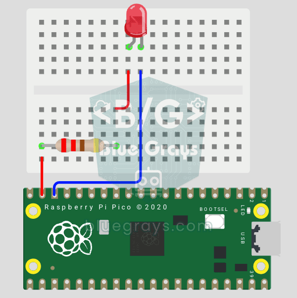
Raspberry Pi Pico: Controlling an External LED (Breadboard)
The next step after the Pico's built-in LED: connect an external LED on a breadboard and control it through pin GP14. You'll learn how to use any of the Pico's GPIO pins as an output, the LED's polarity (long leg = anode/+, short leg = cathode/–) and why a current-limiting resistor (220Ω) is a must. Without the resistor, too much current flows through the LED and it can burn out.
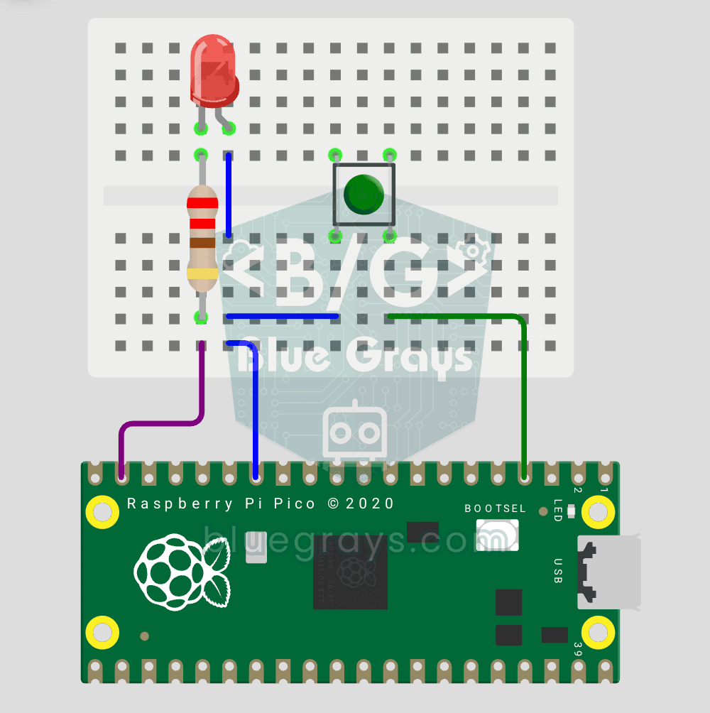
Raspberry Pi Pico Button Controlled LED (Push)
First input project with Pico — button read! LED lights while button is pressed, off when released. This is the big step after LED animations: signal input from the world to Pico. Learn Pin.IN (input mode), Pin.PULL_UP (internal pull-up resistor — standard for buttons), button.value() reading. GP14 LED, GP2 button (internal PULL_UP). Pressed = LOW (0), released = HIGH (1) — reverse logic seems confusing at first but is industry standard.

ESP32 Wi-Fi STA Connection (with LCD Screen)
In this project, we connect the ESP32 to the home Wi-Fi network in Station (STA) mode in a secure, fault-tolerant manner. We store the SSID and password in a separate secrets.h file to prevent leaking to Git, set up an auto-reconnect mechanism, and display the RSSI signal level and IP address on an I2C LCD screen. The internal LED works as a status indicator. It is a production-grade connection manager.

Real-Time Clock from the Internet via ESP32 NTP
The ESP32 connects to Wi-Fi and fetches the real time from NTP (Network Time Protocol) servers with millisecond precision. configTzTime() applies the Turkey time zone (TRT, UTC+3) automatically, and in countries with daylight saving time the DST switch is handled by a POSIX TZ string. The time is printed both to the Serial Monitor and to an optional I2C LCD.