
HLK-PM01: Power ESP32 and Arduino from 220 V Mains Safely
Get 5 V 600 mA from mains with the HLK-PM01: pinout, fuse and varistor choice, isolation distance, enclosure and safety rules for ESP32 and Arduino.

The HLK-PM01 is an isolated AC-DC converter module, smaller than a matchbox, that turns mains voltage directly into 5 V DC. Made by Hi-Link, it is rated at 3 W, so it delivers up to 600 mA at 5 V; the transformer, switching circuit, feedback and output filter are all sealed in resin inside. It has four pins: two go to the mains and two go to your circuit. It is a popular choice for powering ESP32 and Arduino projects such as smart plugs, in-wall light switches or irrigation control boxes directly from the mains, without a separate adapter.
But let's start with a warning: the input side of the HLK-PM01 works with mains voltage, which can be lethal. In this post you'll learn the module's pins, the fuse and varistor you must add, the isolation distance to keep between the mains and 5 V sides, proper enclosure, and the safety rules to follow when powering an ESP32 or Arduino from the mains. In the last section we'll also talk about when a ready-made, certified adapter is a much smarter choice than this module. If you're under 18, do any work on the mains side together with a teacher or an adult who understands electrical work.
What is the HLK-PM01 and how does it work?
The HLK-PM01 is a small switching power supply (SMPS). The mains voltage is first rectified and stored in a capacitor at about 310 V DC. A control chip inside then switches this voltage on and off at tens of kilohertz and feeds it to a tiny high-frequency transformer. The voltage on the transformer's secondary winding is rectified again and filtered, and a feedback circuit holds the output at 5 V. Thanks to the transformer there is no direct electrical connection between input and output; this is called galvanic isolation, and it is exactly what makes the 5 V side safe. Because a high-frequency transformer can be very small, the module is much smaller and lighter than classic adapters with an iron-core transformer. If you want to refresh your memory of the difference between alternating and direct current, see the difference between AC and DC current.
| Feature | Value |
|---|---|
| Input voltage | 100–240 V AC, 50/60 Hz (wide range 90–264 V AC) |
| Output voltage | 5 V DC |
| Output current | Up to 600 mA (3 W) |
| Efficiency | About 70% at full load |
| Output ripple | Typically 50–80 mV |
| No-load consumption | About 0.1 W |
| Isolation voltage | 3000 V AC (between input and output) |
| Protection | Short circuit and overcurrent (recovers by itself when the fault clears) |
| Operating temperature | About –20 to +60 °C |
| Size | 34 × 20 × 15 mm |
HLK-PM01 pinout and the model family
There are four pins underneath the module, and the labels are printed on the body: two AC, one -Vo and one +Vo. The AC pins go to the mains live (L) and neutral (N); the input has no polarity, so it makes no difference to the module which AC pin you connect the live wire to. The fuse should still always be on the live line. -Vo is the negative output, the circuit's GND; +Vo is the 5 V output. The AC pins are at one end of the module and the output pins at the opposite end. This layout is no coincidence; it is designed to keep the mains and the low-voltage side far apart, and you should preserve this separation when designing your own board. The same family also includes models with other output voltages and power ratings:
| Model | Output | Max current | Typical use |
|---|---|---|---|
| HLK-PM01 | 5 V | 600 mA (3 W) | ESP32, Arduino, 1–2 relays |
| HLK-PM03 | 3.3 V | About 900 mA (3 W) | ESP modules that need 3.3 V directly |
| HLK-PM12 | 12 V | 250 mA (3 W) | 12 V relays and small loads |
| HLK-5M05 | 5 V | 1 A (5 W) | Wi-Fi plus a few relays together |
| HLK-10M05 | 5 V | 2 A (10 W) | Short LED strips, projects with displays |
Safe connection circuit: fuse, varistor and capacitors
The HLK-PM01 works on its own, but connecting it to the mains with no protection at all is a serious mistake. If the module fails internally, or there's a sudden voltage surge such as lightning or a large motor switching, something has to limit the problem. The correct order is: the live line goes first to the fuse, then after the fuse to the varistor and the module's AC input; the other end of the varistor connects to neutral. At normal voltage a varistor is almost infinite resistance; when the voltage exceeds its limit it conducts and absorbs the surge. In a very large surge it may fail short, and that is exactly when the fuse blows and cuts the line. So never put the varistor before the fuse. It's important for the fuse to be time-delay (T type), because the moment the module is plugged in, the capacitor inside charges with a brief high current and a fast fuse could blow needlessly. On the output side, an electrolytic and a ceramic capacitor handle the sudden current spikes the ESP32 draws when Wi-Fi starts.
| Component | Recommended value | Position and job |
|---|---|---|
| Fuse | T500 mA 250 V, time-delay | First element on the live line; cuts the line on a fault |
| Varistor (MOV) | 10D471K (300 V AC) or 10D561K (350 V AC) | After the fuse, between L and N; absorbs voltage surges |
| NTC thermistor (optional) | 5D-9 (5 Ω) | In series on the live line; limits inrush current |
| Electrolytic capacitor | 220–470 µF, 10 V or 16 V, low ESR | Between +Vo and -Vo; handles current spikes and ripple |
| Ceramic capacitor | 100 nF | Between +Vo and -Vo, close to the load; filters high-frequency noise |
| TVS diode (optional) | SMBJ5.0A | Between +Vo and -Vo; clips overvoltage peaks at the output |
Isolation distance: separating mains from 5 V
The isolation inside the module withstands 3000 V, but it is very easy to ruin this protection on your own board. Electricity can jump between two conductors in two ways: through the air (clearance) and along the surface of the board (creepage). Dust, moisture and solder flux residue make surface leakage easier. The practical values to keep in mind for hobby projects are: at least 6 mm, preferably 8 mm, between the mains primary side and the 5 V secondary side; and at least 3 mm between live and neutral. On perfboard the hole pitch is 2.54 mm, so two adjacent tracks can never meet this distance.
- Separate zones: Split the board in two; on one side only the mains terminal, fuse, varistor and the module's AC pins, on the other side the 5 V circuit. Traces from the two zones must not pass under or between each other.
- Cut a slot: If you're designing a PCB, put a 1–2 mm wide milled slot between primary and secondary; the slot lengthens the creepage path.
- Cut the tracks on stripboard: If you use stripboard, leave at least three columns empty between the two zones and cut the copper tracks completely with a hobby knife or drill bit. For details see permanent circuits on perfboard.
- Don't forget the relay: The contact side of a relay module also carries mains voltage; apply the same rule to the distance between the relay terminals and the Arduino pins.
- Solder cleanly: Sharp solder spikes and flux residue shorten the distance; clean the board with isopropyl alcohol after soldering. For technique, see the how to solder guide.
- Secure the mains cable: So that it can't tear off the solder joint and touch the 5 V side when pulled, secure it with a screw terminal and a cable tie.
Connecting to Arduino, ESP32 and Raspberry Pi Pico
| HLK-PM01 pin | Arduino Uno | ESP32 DevKit | Raspberry Pi Pico |
|---|---|---|---|
| AC | Live (L) through the fuse | Live (L) through the fuse | Live (L) through the fuse |
| AC | Neutral (N) | Neutral (N) | Neutral (N) |
| +Vo | 5V pin | 5V (VIN) pin | VSYS (pin 39), through a Schottky diode |
| -Vo | GND | GND | GND (e.g. pin 38) |
On the Arduino Uno, connect the module's output to the 5V pin; the VIN pin and DC jack go through the on-board regulator and need at least 7 V, so the board would run unstably on 5 V. On ESP32 DevKit boards the 5V pin feeds the on-board 3.3 V regulator (usually an AMS1117); this regulator needs about 1.1 V of dropout and easily produces 3.3 V from a 5 V input. On the Pico, the VBUS pin is connected directly to USB's 5 V line. If you feed external power into VSYS through a Schottky diode (1N5817 or SS14), the USB and the module won't push current into each other even when both are connected. The diode's roughly 0.3 V drop is not a problem, since VSYS accepts 1.8–5.5 V. For other options see the AMS1117 3.3 V regulator post.
Step-by-step setup and first test
- Place the module and protection components on the perfboard or PCB; check once more the gap between the mains side and the 5 V side and the cut tracks.
- Connect the live wire from the screw terminal to the fuse, the fuse output to one end of the varistor and to one AC pin of the module. Connect neutral to the other end of the varistor and to the module's other AC pin.
- Solder the 470 µF electrolytic capacitor to the output, watching the polarity (long leg to the +Vo side), and add the 100 nF ceramic capacitor next to it.
- Before connecting any Arduino or ESP32, cover the mains section with the enclosure lid or an insulating barrier; only the 5 V output terminal should remain accessible.
- Plug it in and measure at the output terminal with a multimeter: with no load you should see 4.95–5.1 V. For measuring, see the multimeter guide.
- Unplug, wait for the capacitors to discharge, then connect your board. Measure the voltage again under load; it should not fall below 4.75 V.
- Run the circuit for a few hours and check the temperature of the module and enclosure. If it's too hot to touch, the load is too high or ventilation is insufficient.
Power budget: is 600 mA enough?
The module delivers 600 mA, but it isn't a good idea to push this value continuously; designing for at most 70–80% of capacity, about 450 mA average current, keeps the module cool and long-lived. Consider an example smart plug: an ESP32 draws 80–150 mA on average with Wi-Fi on, but brief 300–450 mA spikes occur at connection. A two-channel 5 V relay module needs about 70–80 mA per coil; two relays together draw about 150 mA. Add 20 mA for a 0.96-inch OLED display and you get an average of 250–320 mA, with short peaks approaching the 600 mA limit in the worst case. Although the average is comfortable, the peaks push the limit, so the 470 µF capacitor on the output is a lifesaver here. You calculate power with P = V × I: 5 V × 0.6 A = 3 W. Since efficiency is 70%, the module draws about 4.3 W from the mains and the 1.3 W in between turns into heat; the current on the mains side is only a few tens of milliamps. You can verify the calculations with the Ohm's Law calculator. If you'll add three or four relays, NeoPixel strips or servo motors, move to a more powerful model such as the 5M05 or 10M05.
Measuring the supply voltage with Arduino
You don't need any extra part to see how the power supply behaves under load. The ATmega328P on the Arduino Uno can measure its own supply voltage against the internal 1.1 V reference: the ADC reference is set to AVcc and the measured channel to the 1.1 V bandgap reference. The smaller the reading, the higher the supply; the formula is Vcc = 1.1 × 10²³ / reading. The code below energizes the relay on pin 7 and compares the voltage idle and under load. Because the internal reference can deviate up to 10% from board to board, you can compare the result once with a multimeter and correct the 1125300 constant. If your relay module is the active-low type (energizes with LOW), swap HIGH and LOW in the code.
1// HLK-PM01 çıkışını boşta ve yük altında ölçme / Measure HLK-PM01 output idle and under load
2const int RELAY_PIN = 7;               // röle modülü IN / relay module IN
3
4long readVccMillivolts() {
5  // Referans AVcc, kanal dahili 1,1 V / Reference AVcc, channel internal 1.1 V
6  ADMUX = _BV(REFS0) | _BV(MUX3) | _BV(MUX2) | _BV(MUX1);
7  delay(2);                            // referans otursun / let the reference settle
8  ADCSRA |= _BV(ADSC);                 // dönüşümü başlat / start conversion
9  while (bit_is_set(ADCSRA, ADSC));    // bitmesini bekle / wait until finished
10  uint8_t low = ADCL;                  // önce ADCL okunur / ADCL must be read first
11  uint8_t high = ADCH;
12  long raw = ((long)high << 8) | low;
13  if (raw == 0) return 0;
14  return 1125300L / raw;               // 1,1 x 1023 x 1000 / 1.1 x 1023 x 1000
15}
16
17void setup() {
18  Serial.begin(9600);
19  pinMode(RELAY_PIN, OUTPUT);
20  digitalWrite(RELAY_PIN, LOW);        // röle bırakılmış / relay released
21}
22
23void loop() {
24  long idleMv = readVccMillivolts();
25  digitalWrite(RELAY_PIN, HIGH);       // röleyi çek, yük oluştur / energize relay, add load
26  delay(300);
27  long loadMv = readVccMillivolts();
28  digitalWrite(RELAY_PIN, LOW);
29
30  Serial.print(F("Bosta / Idle: "));
31  Serial.print(idleMv);
32  Serial.print(F(" mV | Yukte / Loaded: "));
33  Serial.print(loadMv);
34  Serial.println(F(" mV"));
35
36  if (loadMv < 4750) {
37    Serial.println(F("UYARI: besleme zayif / WARNING: weak supply"));
38  }
39  delay(3000);
40}
Supply monitoring with ESP32 and Raspberry Pi Pico
On the ESP32, the most typical symptom of a weak supply is the board rebooting by itself while Wi-Fi connects and a Brownout detector was triggered message in the serial monitor. The code below prints the reason for the last reset at startup and reads the 5 V rail on GPIO 34 through a 10 kΩ + 10 kΩ voltage divider. The divider brings 5 V down to 2.5 V, because the ESP32's ADC input can't take more than 3.3 V. You can check the values with the voltage divider calculator, and for details on the problem see ESP32 brownout and Guru Meditation.
1#include <Arduino.h>
2#include "esp_system.h"
3
4const int SENSE_PIN = 34;        // 5 V hattı 10k/10k bölücüyle / 5 V rail via 10k/10k divider
5const uint32_t LOW_MV = 4700;    // uyarı eşiği / warning threshold
6
7const char* resetReasonText(esp_reset_reason_t r) {
8  switch (r) {
9    case ESP_RST_POWERON:  return "Guc verildi / Power-on";
10    case ESP_RST_BROWNOUT: return "Brownout: besleme coktu / supply dropped";
11    case ESP_RST_SW:       return "Yazilim / Software";
12    case ESP_RST_PANIC:    return "Panik / Panic";
13    case ESP_RST_INT_WDT:
14    case ESP_RST_TASK_WDT:
15    case ESP_RST_WDT:      return "Watchdog";
16    default:               return "Diger / Other";
17  }
18}
19
20void setup() {
21  Serial.begin(115200);
22  delay(500);
23  Serial.print("Reset nedeni / Reset reason: ");
24  Serial.println(resetReasonText(esp_reset_reason()));
25  analogReadResolution(12);
26}
27
28void loop() {
29  uint32_t sum = 0;
30  for (int i = 0; i < 16; i++) {
31    sum += analogReadMilliVolts(SENSE_PIN);   // kalibreli mV / calibrated mV
32  }
33  uint32_t railMv = (sum / 16) * 2;           // bölücü oranı 1/2 / divider ratio 1/2
34  Serial.printf("5V hatti / 5V rail: %lu mV\n", (unsigned long)railMv);
35  if (railMv < LOW_MV) {
36    Serial.println("UYARI: besleme dusuk / WARNING: supply low");
37  }
38  delay(1000);
39}
The Raspberry Pi Pico has a built-in divider that divides VSYS by three and is connected to channel GP29 (ADC3); so you can measure the supply voltage without any extra parts. The MicroPython code below averages 16 readings and lights the onboard LED if the voltage drops below 4.4 V. On a Pico powered from the HLK-PM01 through a Schottky diode, the normal value is around 4.6–4.8 V. This code is for the standard Pico; on the Pico W, GP29 is shared with the wireless chip, so the reading is done differently.
1from machine import ADC, Pin
2import time
3
4vsys = ADC(29)            # GP29 = VSYS / 3 (klasik Pico) / GP29 = VSYS / 3 (standard Pico)
5led = Pin(25, Pin.OUT)    # dahili LED / onboard LED
6
7while True:
8    toplam = 0
9    for _ in range(16):
10        toplam += vsys.read_u16()
11    volt = (toplam / 16) * 3.3 / 65535 * 3   # ADC değerini volta çevir / convert reading to volts
12    print("VSYS: {:.2f} V".format(volt))
13    led.value(1 if volt < 4.4 else 0)       # düşükse LED yanar / LED on when low
14    time.sleep(1)
Enclosure: what should a safe housing look like?
- Insulating, flame-retardant box: Use a UL94 V-0 rated ABS or polycarbonate project box. If you'll 3D print one, choose PETG or ASA instead of PLA; PLA starts to soften at around 60 °C.
- Earthing is a must in a metal box: A metal enclosure must be connected to the protective conductor (earth line); get help from an electrician for this. In hobby projects a plastic box is much simpler and safer.
- Secure the cable entry: The mains cable should enter the box through a cable gland or strain relief; when the cable is pulled, the box should take the strain, not the solder joint.
- Add an internal barrier: Inside the box, separate the mains compartment from the 5 V compartment with a plastic partition; a wire that works loose must not be able to cross to the other side.
- Leave ventilation: The module and relays heat up; leave air space in the box, don't squeeze the module into a tight corner, and don't cover it with hot glue.
- Only low voltage should come out: Buttons, sensor cables and the USB port may be accessible from outside; but no metal part carrying mains voltage should be touchable from outside.
- Label it: Write the warning "220 V – unplug before opening" on the box.
When should you choose a ready-made adapter?
Let's be honest: for most projects the safest and cheapest solution is a good CE-marked 5 V USB adapter. A phone charger contains the same kind of switching power supply, but its fuse, isolation distances and housing have been designed and tested by the manufacturer; you only deal with the 5 V side. The HLK-PM01 makes sense when there is already mains voltage inside the device. For example, if you're switching a lamp or an outlet with a relay, the mains cable already enters the box, and a separate adapter would mean an extra cable and an extra socket. Use these criteria when deciding:
- Choose a ready-made adapter: If you're new to electronics, if the project will sit on the desk or next to an outlet, if you need more than 600 mA, or if you can't build a proper enclosure.
- Choose a ready-made adapter: If you're making a school project, a fair stand or a device that children will use; not touching the mains side at all is the biggest safety measure.
- Choose the HLK-PM01: If the device will go into an in-wall box, a distribution box or a lamp body, and already contains a relay or solid-state relay that works with mains voltage.
- Choose the HLK-PM01: If you're building a permanent device, can design a fused and isolated board and place it in a closed enclosure, and can have the circuit checked by someone competent.
- If you need neither: In portable projects don't deal with the mains at all; an 18650 cell with a charger module or a power bank is enough.
Common mistakes and how to fix them
| Mistake | What happens? | Fix |
|---|---|---|
| Not using a fuse | If the module fails, wires heat up and there is a fire risk | Put a T500 mA time-delay fuse on the live line |
| Connecting the varistor before the fuse | When the varistor shorts, nothing is left to cut the line | Order: live → fuse → varistor and module |
| No capacitor on the output | ESP32 resets when Wi-Fi starts, brownout message appears | Add a 470 µF electrolytic and a 100 nF ceramic |
| Exceeding the 600 mA limit | Voltage drops, the module heats up and goes into protection and shuts off | Reduce the load or move to the 5M05 or 10M05 |
| Building the mains side on a breadboard | Exposed contacts, loose connections and arcing | Build the mains side only on a soldered board and in an enclosure |
| Side-by-side layout on perfboard | Surface leakage, arcing, broken isolation | Leave at least 6 mm of gap, cut the tracks |
| Connecting -Vo to earth or neutral | The isolation between input and output is lost | Keep the output completely separate from the mains |
| Uploading code while powered | Your hand and the USB cable come near mains voltage | Unplug before programming |
With the right protection and a solid enclosure, the HLK-PM01 is the most compact way to connect ESP32 and Arduino projects to the mains; but on the mains side, the rules don't bend. Develop your circuit first with a USB adapter, and build the permanent version with the module once everything works. To learn the relay side, see the relay module; for a complete application, the ESP32 smart plug; and for general power options, Arduino power supply. In the BlueGrays app you can explore switching a 220 V bulb with a button and a remote, ESP32 smart lighting and smart irrigation projects, step by step with circuit diagrams and code.
Frequently asked questions
How many amps does the HLK-PM01 deliver?
The HLK-PM01 delivers up to 600 mA at 5 V output, which is 3 W. For long life and low heat, it's good practice to keep the continuous load around 450 mA. If you need more current, look at the HLK-5M05 (5 V 1 A) or the HLK-10M05 (5 V 2 A).
Can the HLK-PM01 power an ESP32?
Yes, it powers an ESP32 easily when connected to the 5V pin of the DevKit board. Because the ESP32 draws brief 300–450 mA current spikes when Wi-Fi connects, you should add a 470 µF electrolytic and a 100 nF ceramic capacitor to the output. Without these capacitors, brownout resets are common.
Are a fuse and varistor required for the HLK-PM01?
The module technically works without them, but for a safe device both are essential. A time-delay fuse on the live line (e.g. T500 mA 250 V) cuts the line on a fault, and a varistor (such as 10D471K) absorbs voltage surges on the mains. The order must always be fuse first, then varistor.
Is the HLK-PM01 output isolated, and is it safe to touch the 5 V side?
Yes, the high-frequency transformer inside the module provides about 3000 V AC of isolation between input and output. This isolation only holds if you leave at least 6 mm of gap between the mains and 5 V sides on your own board and never connect -Vo to neutral or earth. In a solid enclosure the 5 V side can be used safely.
Is it normal for the HLK-PM01 to get warm?
Mild warmth is normal; with about 70% efficiency, more than 1 W of power turns into heat at full load. If the module is too hot to touch, the load is near the 600 mA limit or the box has no airflow. Reduce the load, add ventilation or move to a more powerful model; if it heats up even with no load, the module may be faulty or a counterfeit.
What should I use instead of the HLK-PM01 if I need 3.3 V?
You can use the HLK-PM03, which gives 3.3 V directly; it is also rated 3 W and delivers about 900 mA. The other way is to get 3.3 V from the HLK-PM01's 5 V output with a 3.3 V regulator such as the AMS1117. ESP32 DevKit boards already do this conversion on board.
Projects to build after reading this
See all projects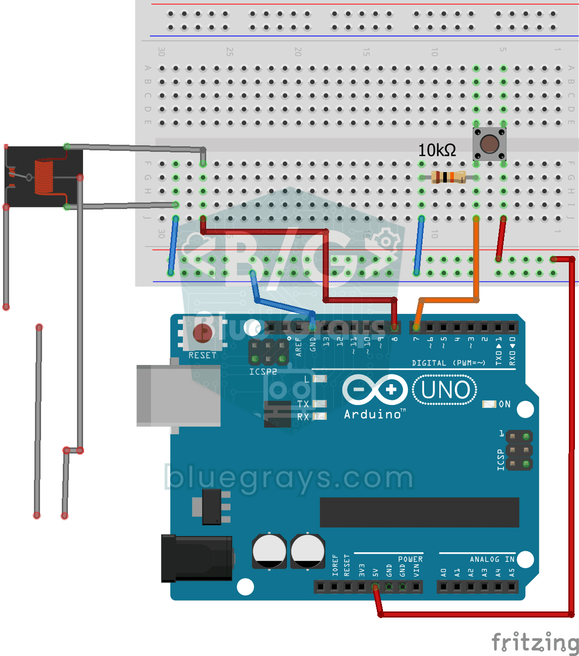
Lighting 220V Bulb with Push Button
As long as you hold the button, a real 220-volt bulb stays lit, and it goes out the moment you let go.
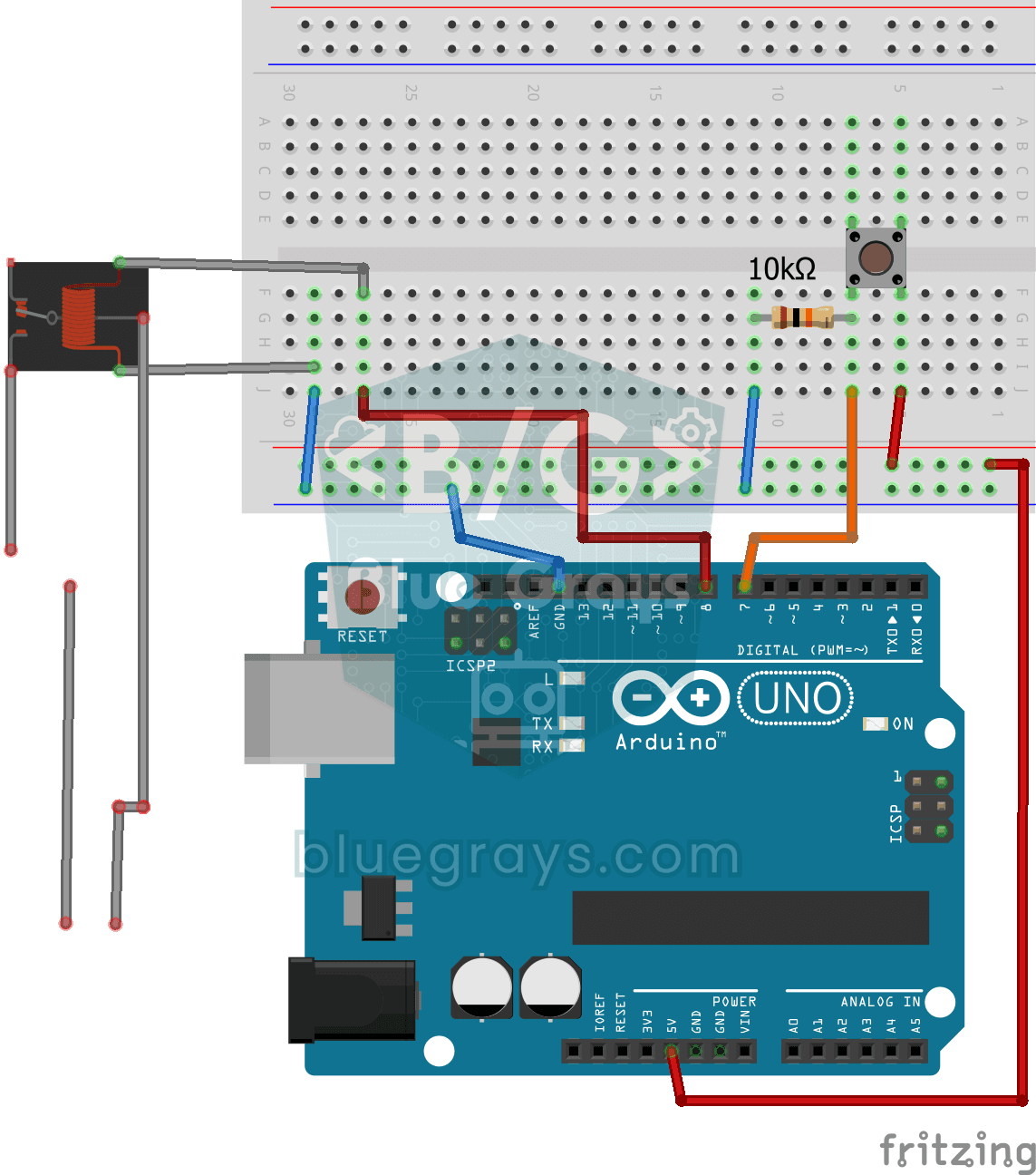
Lighting 220V Bulb with Button (On-Off)
Want to switch a real household bulb on and off with a tiny button? Each time you press the button, the Arduino flips a relay and the bulb lights up; press again and it goes off.
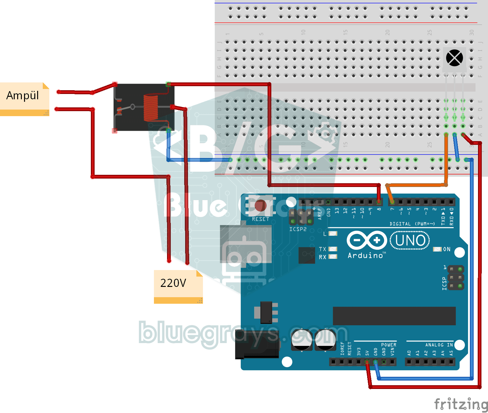
Lighting 220V Bulb with Remote Control
Switch a real light bulb in your home on and off with a TV remote, without getting up from the sofa.

ESP32 Smart Lighting (PIR + LDR + Relay + OLED)
With an ESP32, a PIR motion sensor, an LDR light sensor and a relay module, we turn your hallway, bathroom or pantry into smart lighting. If the room is already bright, the light stays off even when there is motion, so it never wastes energy during the day. The light stays on for 30 seconds, and the time extends automatically while motion continues.

Smart Stair and Corridor Lighting
Step onto the stairs or into the hallway and the lights come on one step at a time in the direction you are walking.

ESP32 Asynchronous Web Server (with IP Display on LCD)
In this project, we’re turning the ESP32 into an asynchronous web server that you can control from your phone or computer on the same Wi-Fi network. Thanks to the ESPAsyncWebServer library, the server can process multiple requests simultaneously (unlike the classic WebServer.h, which blocks on a single request). You’ll be able to open the ESP32’s IP address in a browser and click the ON/OFF buttons (the /on and /off routes) to turn the LED connected to GPIO 5 on and off.
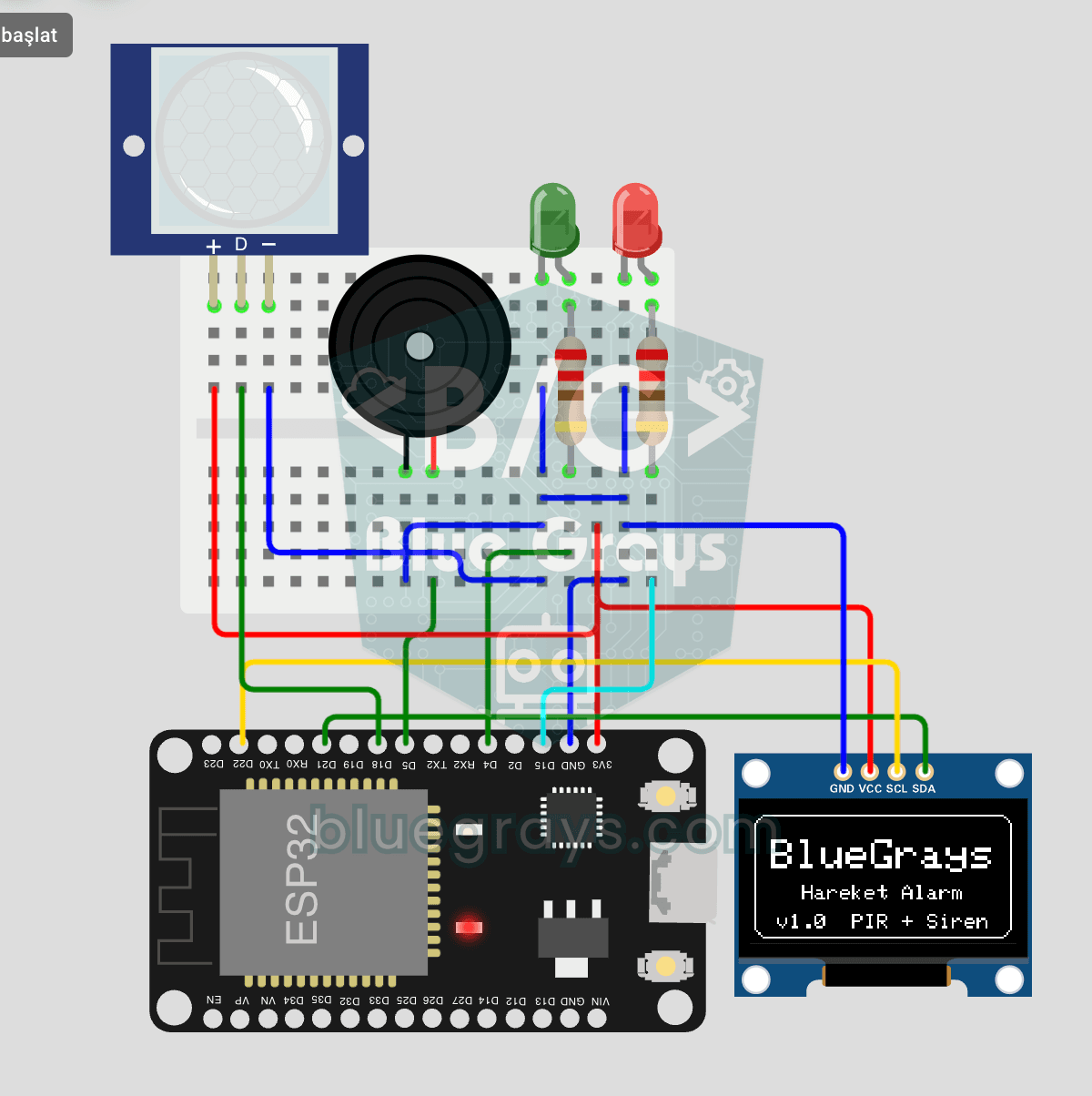
ESP32 Motion Alarm System (PIR + Buzzer + LED + Telegram)
A smart security alarm: when the PIR sensor detects motion, it sounds the buzzer, lights the LED and sends the owner an instant Telegram notification. A 30-second cooldown limits how often the alarm repeats; it does not filter out the PIR sensor's false detections. Use it at home, in a garage, a storeroom or a study.