
AC vs DC Current: Differences, Frequency and RMS Explained
AC vs DC current explained: waveform, 50 Hz frequency, 230 V RMS and 325 V peak, how adapters convert AC to DC, and switching mains loads with a relay or SSR.

The difference between AC and DC current is about how electricity flows in a circuit: in direct current (DC) the current always flows in the same direction and the voltage stays constant; in alternating current (AC) the direction of the current reverses dozens of times per second and the voltage rises and falls as a sine wave. The outlet in your home supplies AC; the battery in your pocket, your phone's battery and the 5 V Arduino gets from USB are DC. This difference isn't just theory; it directly determines which component you can connect where, which range you use on your meter and whether a circuit is safe.
In this post you'll compare the two types of current by waveform, frequency and effective value (RMS), work out why the 230 V at the outlet actually peaks at 325 V, and see step by step how a wall adapter converts AC to DC. Then you'll learn why Arduino, ESP32 and Raspberry Pi Pico run only on DC, and how to control a 230 V lamp safely with a relay or an SSR (solid-state relay).
What is direct current (DC)?
In direct current the source has a plus (+) and a minus (−) terminal, and these polarities never swap. Current leaves the plus terminal, passes through the load and returns to the minus terminal (this is the conventional current direction; the electrons actually move the opposite way). An AA battery gives about 1.5 V, an 18650 lithium cell 3.7 V nominal (4.2 V when fully charged), a USB port 5 V and a car battery about 12 V DC. If you plot voltage against time, you see a flat, horizontal line. As a battery drains, the line slowly sinks, but the direction never changes. That's why polarized parts such as LEDs, diodes, electrolytic capacitors and integrated circuits must be connected the right way round in a DC circuit.
What is alternating current (AC) and how does it work?
Alternating current is produced by generators in power plants: the voltage induced in coils rotating inside a magnetic field points one way for half the rotation and the opposite way for the other half. The result is a sine wave that starts at zero, rises to a positive peak, falls back to zero, goes to a negative peak and returns to zero. Of the two holes in the outlet, one is live and the other is neutral; the voltage of the live relative to the neutral completes a full cycle 50 times per second. The main reason AC is preferred on the grid is that a transformer can easily step the voltage up and down. Electricity is transmitted from the plant at hundreds of kilovolts, so the current is smaller for the same power and the heat loss in the cables (I²R) is reduced. The distribution transformer in your neighbourhood then steps this down to the 230 V used in homes.
| Feature | Direct current (DC) | Alternating current (AC) |
|---|---|---|
| Current direction | Always the same direction | Constantly reverses (100 times per second at 50 Hz) |
| Waveform | Flat line | Sine wave |
| Terminals | Plus (+) and minus (−) | Live (L) and neutral (N) |
| Typical source | Battery, car battery, solar panel, USB, adapter output | Mains outlet, generator, transformer output |
| Voltage conversion | Needs an electronic converter (buck, boost) | Easily done with a transformer |
| Can it be stored? | Yes, in batteries | No, it must first be converted to DC |
| Label symbol | Solid line above, dashed line below | ~ (wave symbol) |
Frequency, period and waveform
Frequency is how many full cycles a wave completes in one second, and it's measured in hertz (Hz). In Turkey and Europe the mains frequency is 50 Hz; so one full wave (period) takes T = 1 / f = 1 / 50 = 20 ms. In every period the current reverses twice and passes through zero twice, so on a 50 Hz grid the current crosses zero 100 times per second. The flicker that some cheap LED bulbs show on camera and the hum of transformers come from this 100 Hz rhythm. Besides sine waves there are also square, triangle and sawtooth waves. Arduino's PWM output, for example, is a square wave switching between 0 and 5 V, but because it never goes negative, it's a pulsed DC whose direction doesn't change. You can take a closer look at this in What is PWM.
| Region | Nominal mains voltage | Frequency |
|---|---|---|
| Turkey | 230 V | 50 Hz |
| European Union | 230 V | 50 Hz |
| United Kingdom | 230 V | 50 Hz |
| USA and Canada | 120 V | 60 Hz |
| Japan | 100 V | 50 Hz in the east, 60 Hz in the west |
RMS (effective value) and peak value
Because AC voltage constantly changes, the answer to "how many volts are at the outlet?" is really a kind of average. A simple arithmetic average comes out as zero, because the positive and negative halves cancel each other. That's why the effective value (RMS, Root Mean Square) is used: the equivalent DC voltage that heats a resistor by the same amount. For a sine wave the formula is simple: Vrms = Vpeak / √2 ≈ 0.707 × Vpeak. The 230 V at the outlet is the RMS value; the peak value is 230 × 1.414 ≈ 325 V, and the peak-to-peak difference is about 650 V. The AC range of a multimeter shows you the RMS value. Power calculations also use the RMS value: a 60 W incandescent bulb at 230 V draws I = P / V = 60 / 230 ≈ 0.26 A, and its hot resistance is R = V² / P ≈ 882 Ω. You can quickly check these calculations with the Ohm's law calculator.
1// AC sinüs dalgası ve etkin değer simülasyonu / AC sine wave and RMS simulation
2const float VPEAK = 325.0;   // şebeke tepe gerilimi / mains peak voltage
3const float FREQ = 50.0;     // şebeke frekansı (Hz) / mains frequency (Hz)
4const int N = 100;           // bir periyottaki örnek sayısı / samples per period
5float vrms = 0;
6
7void setup() {
8  Serial.begin(115200);
9  float sumSq = 0;
10  for (int i = 0; i < N; i++) {
11    float t = (float)i / (FREQ * N);              // zaman (saniye) / time (seconds)
12    float v = VPEAK * sin(2.0 * PI * FREQ * t);   // anlık gerilim / instantaneous voltage
13    sumSq += v * v;                               // karelerin toplamı / sum of squares
14  }
15  vrms = sqrt(sumSq / N);                         // karelerin ortalamasının karekökü / root mean square
16  Serial.print("Vrms = ");
17  Serial.println(vrms, 1);                        // yaklaşık 229.8 / about 229.8
18  delay(2000);
19}
20
21void loop() {
22  static int i = 0;
23  float t = (float)i / (FREQ * N);
24  float ac = VPEAK * sin(2.0 * PI * FREQ * t);
25  // Seri Çizici için etiketli değerler / labeled values for Serial Plotter
26  Serial.print("AC:");
27  Serial.print(ac, 1);
28  Serial.print(",Etkin:");
29  Serial.print(vrms, 1);
30  Serial.print(",Tepe:");
31  Serial.println(VPEAK, 1);
32  i = (i + 1) % N;
33  delay(10);   // grafiği yavaşlat / slow down the plot
34}
The code splits one 50 Hz period into 100 equal parts, computes 325 × sin(2πft) at each point, takes the square root of the mean of the squares and prints about 229.8 V to the Serial Monitor. Then, in loop(), it sends the wave itself, the RMS line and the peak line to the Serial Plotter. On the graph you can see for yourself that the sine reaches 325 V but, in terms of heating effect, is equivalent to a flat 230 V DC line. This is only a simulation; real mains voltage is never connected directly to an Arduino.
AC and DC examples from daily life
| Source / device | Current type | Typical voltage |
|---|---|---|
| Wall outlet | AC | 230 V, 50 Hz |
| Doorbell transformer output | AC | 8–12 V |
| AA / AAA battery | DC | 1.5 V |
| 18650 Li-ion cell | DC | 3.7 V nominal, 4.2 V fully charged |
| 9 V battery | DC | 9 V |
| USB port and phone charger | DC | 5 V (9–20 V with fast charging) |
| Car battery | DC | 12 V (about 14 V with the engine running) |
| Solar panel | DC | 6–40 V depending on the panel |
| Arduino Uno I/O pins | DC | 0 and 5 V |
| ESP32 and Raspberry Pi Pico pins | DC | 0 and 3.3 V |
How does an adapter convert AC to DC?
- Stepping down the voltage: In a classic adapter an iron-core transformer steps 230 V AC down to, say, 12 V AC. In modern switch-mode (SMPS) adapters this is done by a small transformer running at high frequency.
- Rectification: A bridge rectifier made of four diodes flips the negative half of the sine so the current always flows in the same direction. The output no longer reverses but still ripples at 100 Hz.
- Filtering: A large electrolytic capacitor charges at the peaks and supplies current to the load in the valleys between them, smoothing the ripple.
- Regulation: A linear regulator such as the 7805, or a switching circuit, holds the output at a constant 5 V, 9 V or 12 V even when the input voltage and the load change.
Let's try a simple calculation: the peak value of a transformer with a 12 V AC output is 12 × 1.414 ≈ 17 V. Since about 1.4 V is dropped across the two diodes in the bridge, the capacitor charges to about 15.6 V. If the load draws 0.5 A and the filter capacitor is 2200 µF, the ripple is about ΔV = I / (2 × f × C) = 0.5 / (2 × 50 × 0.0022) ≈ 2.3 V. When you feed this rippling voltage to a 7805 regulator, you get a clean 5 V at the output. Today's phone chargers, on the other hand, first rectify the mains directly to get about 325 V DC, then switch it on and off at tens of kilohertz and pass it through a small transformer; that's why they're as small and light as the palm of your hand. The HLK-PM01 AC-DC converter is a nice ready-made example; you'll find the role of the filter component in What is a capacitor.
Why does Arduino run on DC?
A microcontroller contains thousands, even millions, of transistors, and they decide between "0" and "1" relative to a constant supply voltage: on the Arduino Uno, 0 V is logic 0 and 5 V is logic 1. If the supply reversed every 10 ms, the processor would switch off and on 100 times per second, everything in RAM would be wiped and the reverse voltage would permanently damage the chip. That's why all of Arduino's power inputs require DC: 5 V from USB, regulated 5 V on the 5V pin, or 7–12 V from the DC jack and the VIN pin. The regulator on the board steps this voltage down to 5 V, and a separate regulator steps it down to 3.3 V. The ESP32 and Raspberry Pi Pico run on 3.3 V; even applying more than 3.3 V to their pins can damage them. We cover board power in detail in Arduino power supply.
Learning to read the adapter label protects you from many failures. A typical label has two lines such as INPUT: 100–240V ~ 50/60Hz 0.3A and OUTPUT: 9V 1A. The input line shows that the adapter can work on both 230 V/50 Hz and 120 V/60 Hz grids, and the output line shows the DC voltage and maximum current it will supply. The output current must be equal to or greater than what the circuit draws; a 2 A adapter doesn't force 2 A into a circuit that draws 500 mA, the circuit only draws what it needs. The small circle symbol on the label shows whether the centre pin of the plug is positive or negative; for Arduino the centre pin must be positive. In battery-powered projects you can estimate run time with the battery life calculator.
Controlling AC loads with Arduino: relay and SSR
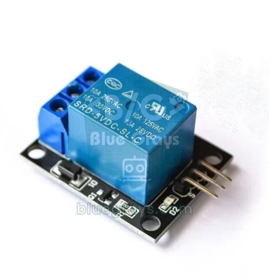
An Arduino pin can safely source only about 20 mA and produces only a 5 V DC signal; it can't drive a 230 V lamp, fan or pump directly. The solution is to use a switch that separates the low-voltage control side from the high-voltage power side. An electromechanical relay closes metal contacts mechanically when 5 V is applied to its coil; there's no electrical connection between the coil and the contacts, which is called galvanic isolation. An SSR (solid-state relay) uses an optocoupler and a triac instead of moving parts. Most AC-type SSRs have a zero-cross feature, meaning they switch the load on at the moment the voltage crosses zero, which reduces sparks and electrical noise. For details, see relay module and SSR solid-state relay.
| Feature | Electromechanical relay | AC SSR |
|---|---|---|
| Switching | Mechanical contact | Triac (semiconductor) |
| Sound | A click on every switching | Silent |
| Lifespan | About 100,000 switching operations electrically | No mechanical wear, very long |
| Load type | AC and DC (according to the label ratings) | AC only (a DC-type SSR is needed for DC) |
| Leakage when off | None | Can be a few mA |
| Heating | Very little | Heats with load current, needs a heatsink at high current |
| Typical rating | 10 A 250 V AC | 25 A, 24–380 V AC (input 3–32 V DC) |
| Connection | Arduino Uno | ESP32 | Raspberry Pi Pico |
|---|---|---|---|
| Relay module VCC | 5V | VIN (USB 5 V) | VBUS (USB 5 V) |
| Relay module GND | GND | GND | GND |
| Relay module IN | D7 | GPIO 26 | GP15 |
| Button (other end to GND) | D2 | GPIO 27 | GP14 |
1// Buton ile 230 V lambayı röleyle aç-kapat / Toggle a 230 V lamp with a relay and button
2const int BUTTON_PIN = 2;              // buton D2-GND / button D2-GND
3const int RELAY_PIN = 7;               // röle IN pini / relay IN pin
4const bool RELAY_ACTIVE_LOW = true;    // çoğu modül LOW ile çeker / most modules trigger on LOW
5
6bool relayOn = false;
7bool lastButton = HIGH;
8unsigned long lastChange = 0;
9
10void setRelay(bool on) {
11  if (RELAY_ACTIVE_LOW) {
12    digitalWrite(RELAY_PIN, on ? LOW : HIGH);
13  } else {
14    digitalWrite(RELAY_PIN, on ? HIGH : LOW);
15  }
16}
17
18void setup() {
19  Serial.begin(9600);
20  pinMode(BUTTON_PIN, INPUT_PULLUP);   // dahili pull-up direnci / internal pull-up resistor
21  pinMode(RELAY_PIN, OUTPUT);
22  setRelay(false);                     // açılışta lamba kapalı / lamp off at startup
23}
24
25void loop() {
26  bool reading = digitalRead(BUTTON_PIN);
27  if (reading != lastButton && millis() - lastChange > 50) {   // 50 ms debounce
28    lastChange = millis();
29    lastButton = reading;
30    if (reading == LOW) {              // butona basıldı / button pressed
31      relayOn = !relayOn;
32      setRelay(relayOn);
33      Serial.println(relayOn ? "Lamba ACIK / Lamp ON" : "Lamba KAPALI / Lamp OFF");
34    }
35  }
36}
Every time you press the button the relay changes state and the lamp turns on or off. The code filters out the button's mechanical bounce with a simple 50 ms debounce, so a single press isn't read as several presses. Most relay modules on the market are active low, meaning the relay pulls in when the IN pin is LOW; if your module is active high, just set RELAY_ACTIVE_LOW to false. The setRelay(false) line at the end of setup() guarantees the lamp starts off when the board powers up. You can run the same code on the ESP32 with BUTTON_PIN = 27 and RELAY_PIN = 26; only note that some 5 V relay modules may not switch reliably with a 3.3 V signal, in which case add a transistor in between or choose a 3.3 V-compatible module.
Measuring DC voltage with a Raspberry Pi Pico (MicroPython)
You can also see the steady nature of DC by measuring it. The Pico's ADC input reads DC voltage in the 0–3.3 V range; to measure higher voltages you use a voltage divider. With a 100 kΩ (R1) and a 33 kΩ (R2) resistor the division ratio is 33 / 133 ≈ 0.248; so a 9 V battery reaches the pin as about 2.23 V, and you can measure up to about 13.3 V. Connect R1 between the battery's plus terminal and GP26, R2 between GP26 and GND, and the battery's minus to the Pico's GND. The program reads the 16-bit raw value every second and calculates the input voltage by reversing the division ratio. Don't use this method for AC: the negative half-waves apply a reverse voltage to the pin and damage the ADC. If you need to monitor the mains, isolated voltage modules such as the ZMPT101B or the ACS712 current sensor are used. You can choose the resistor values for your own source with the voltage divider calculator.
1from machine import ADC
2import time
3
4adc = ADC(26)            # GP26 = ADC0
5R1 = 100000              # üst direnç (ohm) / top resistor (ohm)
6R2 = 33000               # alt direnç (ohm) / bottom resistor (ohm)
7VREF = 3.3               # ADC referans gerilimi / ADC reference voltage
8
9while True:
10    raw = adc.read_u16()                     # 0-65535 arası ham değer / raw value 0-65535
11    v_pin = raw * VREF / 65535               # pindeki gerilim / voltage at the pin
12    v_in = v_pin * (R1 + R2) / R2            # giriş gerilimi / input voltage
13    print("Pin: {:.2f} V  Giris: {:.2f} V".format(v_pin, v_in))
14    time.sleep(1)
Project ideas with AC and DC
- Remote-controlled lamp: Turn a 230 V bulb on and off from a TV remote with an IR receiver and a relay.
- Smart plug: Combine an ESP32 with a relay and control the outlet from your phone; the details are in ESP32 smart plug.
- Automatic hallway light: When the PIR sensor detects motion, switch the lamp on for a few minutes through an SSR.
- Battery voltmeter: Measure battery voltage with a voltage divider, show it on a display and give a warning at low voltage.
- Solar-powered irrigation: Charge a battery from the solar panel's DC output and run a mini water pump with a MOSFET.
- Temperature-controlled heater: Build an Arduino thermostat that switches an AC heater on and off with an SSR.
Common mistakes and how to fix them
| Mistake | Result | Fix |
|---|---|---|
| Plugging an AC-output adapter into Arduino | The board doesn't work properly, the regulator gets hot | Check the output symbol on the label, use a DC adapter |
| Using the multimeter on the wrong range | The DC range at the outlet shows near zero or a meaningless value | Choose AC (V~) at the outlet, DC on a battery |
| Ignoring the peak value | A part assumed to withstand 230 V fails at 325 V | Choose mains-side parts rated for at least 400 V |
| Connecting a bare relay coil directly to a pin | The pin is damaged by overcurrent or the coil's reverse voltage | Use a ready-made relay module or add a transistor and a flyback diode |
| Switching a DC load with an AC SSR | Once the SSR turns on it never turns off | Use a DC-type SSR or a MOSFET for DC loads |
| Not joining the GNDs of DC sources | Measurements and signals are unstable | Join all the negatives on the low-voltage side to a common GND |
| Running 230 V across a breadboard | Risk of short circuit, fire and electric shock | Keep the mains side in insulated terminals and a closed box |
Once you understand the difference between AC and DC, reading adapter labels, choosing the right power supply and controlling 230 V loads safely become much easier: the microcontroller always stays on the low-voltage DC side, and a relay or SSR builds the bridge to the mains. In the BlueGrays app you can look at projects such as switching a 220 V bulb with a button and a remote, smart hallway lighting, ESP32 smart lighting and a digital voltmeter, step by step with circuit diagrams and code, and put what you learned here into practice right away.
Frequently asked questions
What is the difference between AC and DC current?
In direct current (DC) the current always flows in the same direction and the voltage is constant; batteries, car batteries and USB are examples. In alternating current (AC) the direction of the current constantly changes and the voltage rises and falls as a sine wave. Outlets in Turkey supply 230 V, 50 Hz AC.
Is a home outlet AC or DC?
A home outlet supplies alternating current (AC). In Turkey the nominal voltage is 230 V RMS and the frequency is 50 Hz; the peak voltage reaches about 325 V. Devices such as phones, computers and Arduino use this AC after an adapter converts it to DC.
Why does a battery give DC and not AC?
The chemical reaction inside a battery pushes electrons in the same direction, from the minus terminal to the plus terminal; so the polarity stays fixed and the output is DC. AC energy can't be stored directly; even rechargeable batteries get DC from an adapter while charging.
Is AC or DC more dangerous?
Both are lethal at high voltage. At the same voltage, 50–60 Hz AC is generally considered more dangerous because it can disturb the heart rhythm and cause muscle contraction that makes you unable to let go of the wire. The 5–12 V DC in Arduino projects is considered safe to touch with dry skin.
Can I connect an AC adapter to Arduino?
No, all of Arduino's power inputs require DC: 5 V from USB, or 7–12 V from the DC jack and the VIN pin. An AC-output adapter makes the board malfunction and the regulator overheat. Check that the output symbol on the adapter label is DC and that the centre pin is positive.
Can a relay control both AC and DC loads?
An electromechanical relay can switch both AC and DC loads, but the DC rating is usually lower; a typical 5 V relay is rated 10 A at 250 V AC but 10 A at only 30 V DC. An AC-type SSR works only with AC loads; for DC loads you need a DC-type SSR or a MOSFET.
Projects to build after reading this
See all projects
LED Blink
The very first hello of electronics: switching a single LED on and off. The Arduino turns the LED on and off at short intervals, so the light blinks quickly.
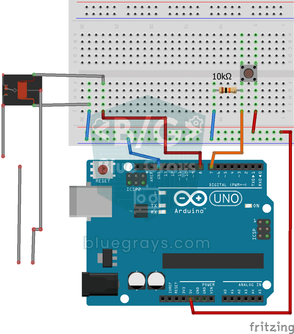
Lighting 220V Bulb with Push Button
As long as you hold the button, a real 220-volt bulb stays lit, and it goes out the moment you let go.
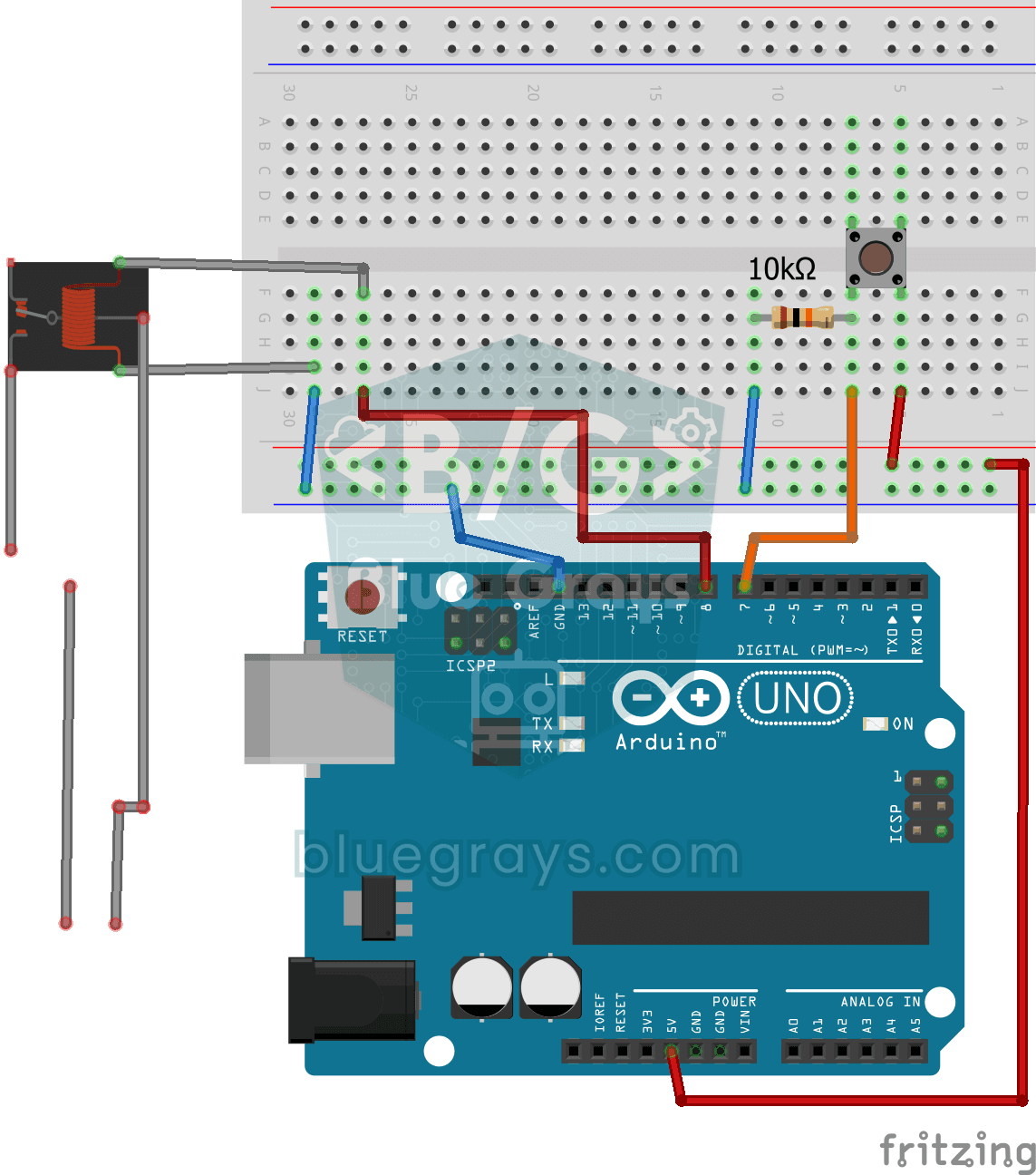
Lighting 220V Bulb with Button (On-Off)
Want to switch a real household bulb on and off with a tiny button? Each time you press the button, the Arduino flips a relay and the bulb lights up; press again and it goes off.
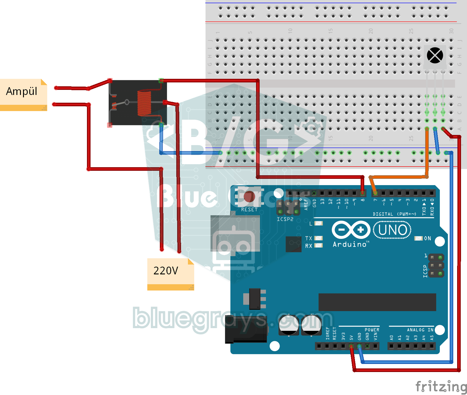
Lighting 220V Bulb with Remote Control
Switch a real light bulb in your home on and off with a TV remote, without getting up from the sofa.
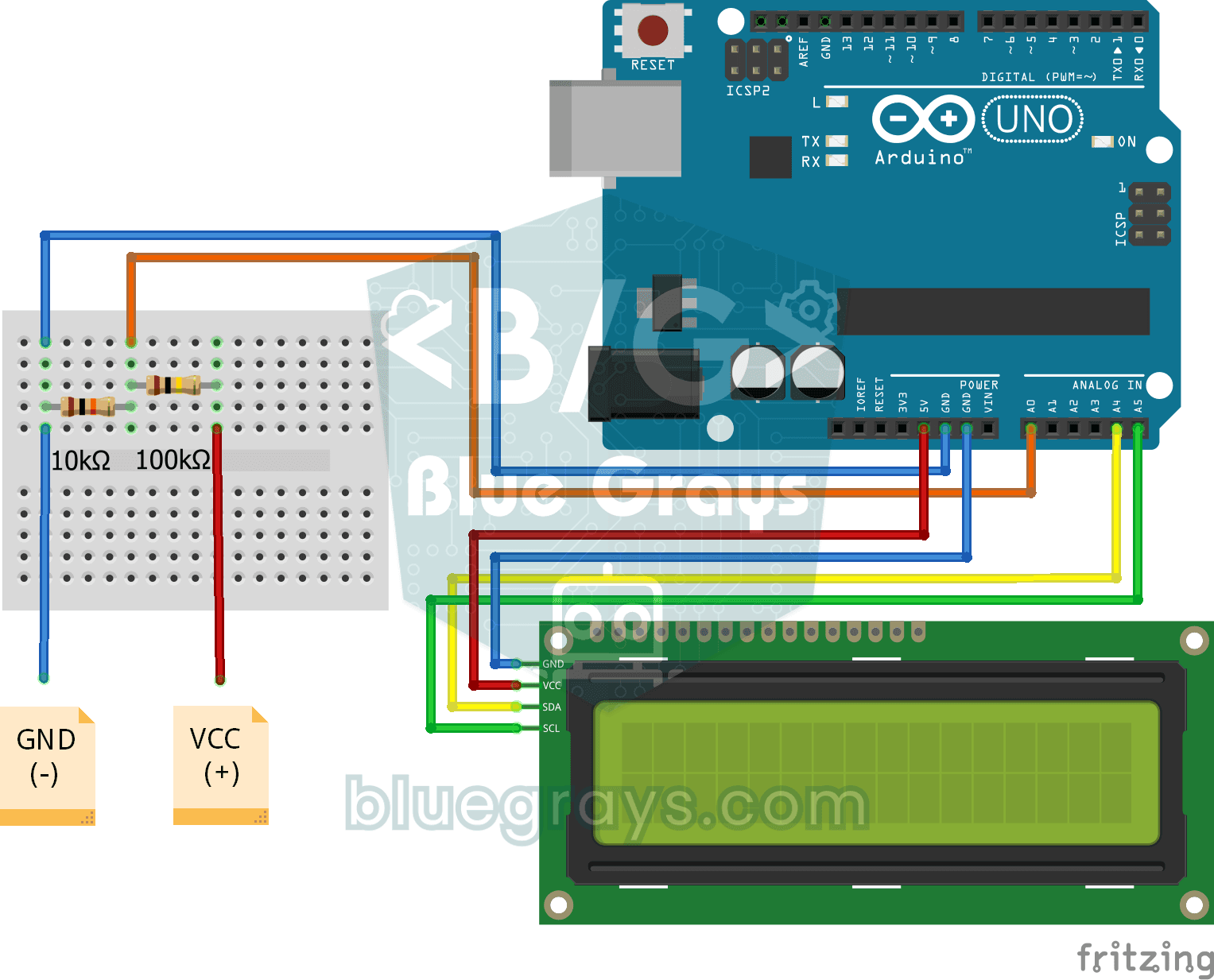
Digital Voltmeter with LCD Display
Find out how much voltage a battery or power adapter gives with a meter you built yourself.

Smart Stair and Corridor Lighting
Step onto the stairs or into the hallway and the lights come on one step at a time in the direction you are walking.

ESP32 Smart Lighting (PIR + LDR + Relay + OLED)
With an ESP32, a PIR motion sensor, an LDR light sensor and a relay module, we turn your hallway, bathroom or pantry into smart lighting. If the room is already bright, the light stays off even when there is motion, so it never wastes energy during the day. The light stays on for 30 seconds, and the time extends automatically while motion continues.

Smart Irrigation Station
A gardener that waters your plants on its own, so they don't dry out while you're on vacation.