
ESP32 Smart Plug: Relay, Web Panel and NTP Timer Tutorial
Build a Wi-Fi ESP32 smart plug: relay and HLK-PM01 wiring, on/off web panel, NTP schedule timer, load limits and 230 V safety rules, with full code.

An ESP32 smart plug turns an ordinary socket into a device you can switch on and off from your phone or computer over Wi-Fi, and that can even run by itself at set times. The idea is simple: the ESP32 joins your home network and serves a small web panel; when you press "On" in the panel, the ESP32 energizes a relay, and the relay closes the live line of the socket to power the connected device. To power the whole setup from the mains, a tiny AC-DC module called the HLK-PM01 converts 230 V to 5 V, so you don't need a separate adapter inside the enclosure.
In this guide you'll go step by step through choosing parts, calculating the power budget, wiring, writing the code with a web panel, and adding a countdown timer and a daily NTP schedule. However, this project works with 230 V mains voltage and doesn't forgive mistakes. That's why there is one main rule throughout the article: test everything at low voltage first; once the code and wiring work flawlessly, move to the mains following the enclosure and insulation rules. If you have no experience with mains wiring, do the last step under the supervision of someone who does.
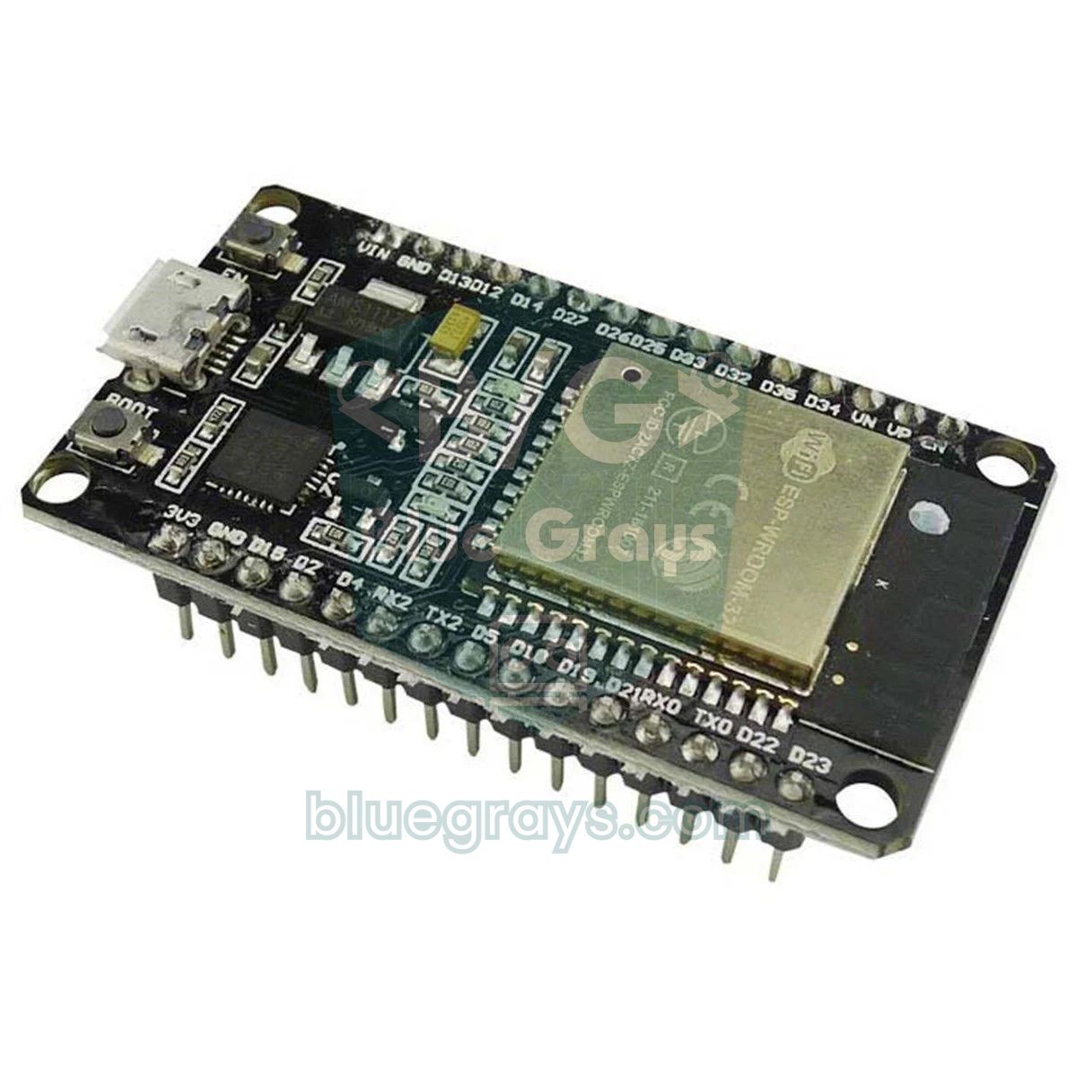
What is an ESP32 smart plug and how does it work?
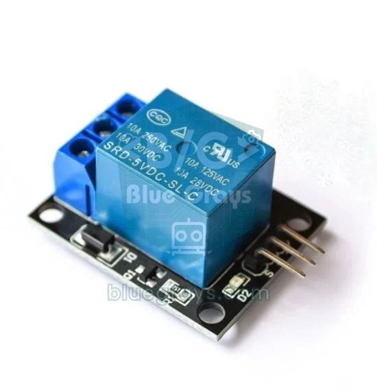
Commercial smart plugs contain the same three blocks: a Wi-Fi microcontroller, a switching element (usually a relay) and a small power supply that makes low voltage from the mains. In our version the ESP32 handles the Wi-Fi connection, the web server and the clock. The relay switches the 230 V load while keeping it electrically isolated from the ESP32's weak 3.3 V signal; when current flows through the coil, the contact inside closes and you hear it as an audible "click". The HLK-PM01 is an enclosed switching power supply with isolation between its input and output; from a 100–240 V AC input it gives 5 V DC at up to 3 W (600 mA). For its internal structure and protection circuit, see the HLK-PM01 AC-DC converter article.
| Part | Job | Key value |
|---|---|---|
| ESP32 DevKit | Wi-Fi, web panel, timer and NTP clock | 3.3 V logic, 250–350 mA peak current while transmitting Wi-Fi |
| 1-channel 5 V relay module | Opens and closes the live line of the socket | Contact: 10 A 250 V AC (SRD-05VDC-SL-C) |
| HLK-PM01 | Converts 230 V AC to 5 V DC | 5 V, 600 mA (3 W), isolated |
| Fuse and varistor | Protect the HLK-PM01 input against short circuits and overvoltage | For example a 0.5 A slow-blow fuse, a 275 V AC varistor (10D431K) |
| Push button | Manual on/off from the enclosure | GPIO 27, internal pull-up |
| Project box and earthed socket | Insulation and touch safety | Flame-retardant UL94 V-0 plastic |
Power budget: is the HLK-PM01 enough?
| Consumer | Typical current (5 V rail) | Note |
|---|---|---|
| ESP32 (Wi-Fi connected, idle) | 80–120 mA | The regulator on the board steps 5 V down to 3.3 V |
| ESP32 (Wi-Fi transmit peak) | 250–350 mA (short-lived) | Should be smoothed with a capacitor |
| Relay coil (5 V) | 70–90 mA | Only while the relay is energized |
| Status LEDs | 5–10 mA | Module and board LEDs |
| Total (worst case) | About 450 mA | HLK-PM01 limit is 600 mA |
As the table shows, a single-relay smart plug fits within the HLK-PM01's 600 mA capacity, but the margin isn't large. That's why placing an electrolytic capacitor of at least 470 µF close to the ESP32's 5V (VIN) pin, with a 100 nF ceramic capacitor next to it, prevents the voltage from sagging and the board from resetting during Wi-Fi current peaks and the moment the relay pulls in. If you use a four-channel relay and energize all of them at once, the coils alone exceed 300 mA; in that case you should choose a stronger module such as the 5 W HLK-5M05. You can quickly check current and power calculations with the Ohm's Law calculator.
Wiring diagram: ESP32, relay and HLK-PM01
| Pin | Connects to | Note |
|---|---|---|
| HLK-PM01 AC inputs | Mains L and N (after the fuse and varistor) | In the high-voltage compartment of the enclosure |
| HLK-PM01 +Vo | ESP32 5V (VIN) and relay module VCC | Disconnect the mains while uploading the program |
| HLK-PM01 -Vo | ESP32 GND and relay module GND | Common ground |
| Relay IN | ESP32 GPIO 26 | A safe pin that produces no signal at boot |
| Button | GPIO 27 and GND | INPUT_PULLUP, no external resistor needed |
| Status LED | GPIO 2 | Built into most DevKit boards |
| Relay COM | Mains live (L), after the fuse | Only the live line is switched |
| Relay NO | Live terminal of the socket | Normally open: the socket is dead when the relay releases |
| Neutral (N) and earth (PE) | Straight to the socket's N and earth terminals | Doesn't pass through the relay, continues uninterrupted |
There's a reason we chose GPIO 26 for the relay: GPIO 0, 2, 12 and 15 are boot (strapping) pins and affect how the board starts; GPIO 1 and 3 are reserved for the serial port, 6–11 for the internal flash memory, and GPIO 5 and 14 also produce short pulses at boot. GPIO 26 does none of these. GPIO 2 is fine because it only drives the board LED as an output. Using the relay's NO (normally open) terminal is also important: when the ESP32 is off, resetting or has failed, the relay releases and the socket stays dead. If you use the NC terminal, the opposite happens and in a fault the device keeps running.
Test at low voltage first
- Power the ESP32 from the USB cable only; don't connect the HLK-PM01 at this stage. Connect the relay module's VCC to the ESP32's 5V (VIN) pin, GND to GND and IN to GPIO 26.
- Connect a low-voltage load to the relay's COM and NO terminals instead of 230 V: a 12 V adapter with a short LED strip, or a 5 V-powered LED with a 220 Ω resistor, is enough.
- Upload the test code below and open the Serial Monitor at 115200 baud; the relay should click every 2 seconds and the LED should blink.
- If the relay works the wrong way round (the load goes off while the screen says "ON"), change the RELAY_ACTIVE_LOW value in the code.
- Then upload the web panel code, switch on and off from your phone and try the timer; reset the ESP32 and check that the relay starts off, and that the board doesn't freeze when Wi-Fi drops.
- Run the setup for a full day at low voltage and watch the NTP schedule switch on and off at the right times; only after that move on to the mains installation.
1// Röle testi / Relay test
2const int  RELAY_PIN = 26;          // Röle IN pini / Relay IN pin
3const bool RELAY_ACTIVE_LOW = true; // Çoğu modül LOW ile çeker / Most modules energize on LOW
4
5void relaySet(bool on) {
6  if (RELAY_ACTIVE_LOW) digitalWrite(RELAY_PIN, on ? LOW : HIGH);
7  else                  digitalWrite(RELAY_PIN, on ? HIGH : LOW);
8}
9
10void setup() {
11  Serial.begin(115200);
12  pinMode(RELAY_PIN, OUTPUT);
13  relaySet(false);                  // kapalı başla / start off
14}
15
16void loop() {
17  relaySet(true);
18  Serial.println("Role ACIK / Relay ON");
19  delay(2000);
20  relaySet(false);
21  Serial.println("Role KAPALI / Relay OFF");
22  delay(2000);
23}
The relaySet() function translates the "on" and "off" commands into the module's trigger logic. Most relay modules on the market are active-LOW: the relay pulls in when the IN pin is pulled to GND. Managing this inverted logic with a single constant (RELAY_ACTIVE_LOW) instead of thinking about it everywhere in the code prevents mistakes. There's another advantage: while the ESP32 boots or resets, the pins are inputs, and an active-LOW module with a floating IN pin doesn't energize by itself during this time. For the relay's internal structure and driver circuit, take a look at What Is a Relay Module?.
Smart plug code with a web panel
If the test worked, you can move on to the main code. The WebServer library that ships with the ESP32 Arduino core needs no extra installation and works the same in core versions 2.x and 3.x. The code serves a control panel on the home page, commands at /on, /off, /toggle and /timer?min=30, and the plug's state as JSON at /state. The panel polls /state every 2 seconds, so you also see changes made with the button on the enclosure or by the schedule on your phone. Don't forget to change the Wi-Fi name and password at the top of the code to your own network; the ESP32 connects only to 2.4 GHz networks. If you want instant updates, see ESP32 Web Server and WebSocket.
1#include <WiFi.h>
2#include <WebServer.h>
3#include <ESPmDNS.h>
4#include <time.h>
5
6const char* WIFI_SSID = "WIFI_ADI";          // Wi-Fi adın / your Wi-Fi name
7const char* WIFI_PASS = "WIFI_SIFRESI";      // Wi-Fi şifren / your Wi-Fi password
8
9const int  RELAY_PIN  = 26;                  // Röle IN / Relay IN
10const int  BUTTON_PIN = 27;                  // Yerel buton / Local button
11const int  LED_PIN    = 2;                   // Durum LED'i / Status LED
12const bool RELAY_ACTIVE_LOW = true;          // LOW tetiklemeli modül / Active-LOW module
13
14// Günlük program (gece yarısından itibaren dakika) / Daily schedule (minutes after midnight)
15int  onMinute  = 18 * 60 + 30;               // 18:30 aç / turn on
16int  offMinute = 23 * 60;                    // 23:00 kapat / turn off
17bool scheduleEnabled = true;
18
19WebServer server(80);
20bool relayOn = false;
21bool timerActive = false;
22unsigned long offAtMs = 0;
23int  lastCheckedMinute = -1;
24
25const char PAGE[] PROGMEM = R"rawliteral(
26<!DOCTYPE html><html><head><meta charset="utf-8">
27<meta name="viewport" content="width=device-width,initial-scale=1">
28<title>Akıllı Priz</title>
29<style>
30body{font-family:sans-serif;text-align:center;background:#0f172a;color:#e2e8f0}
31button{font-size:20px;margin:6px;padding:12px 22px;border:0;border-radius:10px;color:#fff}
32.on{background:#16a34a}.off{background:#dc2626}.t{background:#2563eb}
33</style></head><body>
34<h2>ESP32 Akıllı Priz</h2>
35<p id="s">...</p><p id="z"></p>
36<button class="on" onclick="go('/on')">AÇ</button>
37<button class="off" onclick="go('/off')">KAPAT</button><br>
38<button class="t" onclick="go('/timer?min=15')">15 dk</button>
39<button class="t" onclick="go('/timer?min=30')">30 dk</button>
40<button class="t" onclick="go('/timer?min=60')">60 dk</button>
41<script>
42function show(d){
43  document.getElementById('s').textContent='Priz: '+(d.on?'AÇIK':'KAPALI');
44  document.getElementById('z').textContent='Saat '+d.time+(d.left>0?' | Kalan: '+d.left+' dk':'');
45}
46function go(u){fetch(u).then(r=>r.json()).then(show);}
47setInterval(()=>go('/state'),2000);
48go('/state');
49</script></body></html>
50)rawliteral";
51
52void relaySet(bool on) {
53  relayOn = on;
54  if (RELAY_ACTIVE_LOW) digitalWrite(RELAY_PIN, on ? LOW : HIGH);
55  else                  digitalWrite(RELAY_PIN, on ? HIGH : LOW);
56  digitalWrite(LED_PIN, on ? HIGH : LOW);
57}
58
59String timeText() {
60  struct tm t;
61  if (!getLocalTime(&t, 10)) return "--:--";   // saat henüz yok / time not synced yet
62  char buf[16];
63  snprintf(buf, sizeof(buf), "%02d:%02d", t.tm_hour, t.tm_min);
64  return String(buf);
65}
66
67long minutesLeft() {
68  if (!timerActive) return 0;
69  long ms = (long)(offAtMs - millis());
70  return ms > 0 ? (ms + 59999L) / 60000L : 0;
71}
72
73void sendState() {
74  String json = "{\"on\":";
75  json += relayOn ? "true" : "false";
76  json += ",\"time\":\"";
77  json += timeText();
78  json += "\",\"left\":";
79  json += String(minutesLeft());
80  json += "}";
81  server.send(200, "application/json", json);
82}
83
84void handleOn()  { timerActive = false; relaySet(true);  sendState(); }
85void handleOff() { timerActive = false; relaySet(false); sendState(); }
86
87void handleTimer() {
88  int m = server.arg("min").toInt();
89  if (m < 1 || m > 720) {                      // 1-720 dakika / 1-720 minutes
90    server.send(400, "text/plain", "min 1-720");
91    return;
92  }
93  relaySet(true);
94  offAtMs = millis() + (unsigned long)m * 60000UL;
95  timerActive = true;
96  sendState();
97}
98
99void setup() {
100  Serial.begin(115200);
101  pinMode(RELAY_PIN, OUTPUT);
102  pinMode(LED_PIN, OUTPUT);
103  pinMode(BUTTON_PIN, INPUT_PULLUP);
104  relaySet(false);                             // güvenli başlangıç: kapalı / safe start: off
105
106  WiFi.mode(WIFI_STA);
107  WiFi.setAutoReconnect(true);
108  WiFi.begin(WIFI_SSID, WIFI_PASS);
109  unsigned long t0 = millis();
110  while (WiFi.status() != WL_CONNECTED && millis() - t0 < 20000) {
111    delay(500);
112    Serial.print(".");
113  }
114  Serial.println();
115  Serial.print("IP: ");
116  Serial.println(WiFi.localIP());
117
118  configTzTime("<+03>-3", "pool.ntp.org", "time.google.com");   // Türkiye UTC+3 / Turkey UTC+3
119
120  if (MDNS.begin("akillipriz")) {
121    Serial.println("http://akillipriz.local");
122  }
123
124  server.on("/", []() { server.send(200, "text/html; charset=utf-8", PAGE); });
125  server.on("/state", sendState);
126  server.on("/on", handleOn);
127  server.on("/off", handleOff);
128  server.on("/toggle", []() { timerActive = false; relaySet(!relayOn); sendState(); });
129  server.on("/timer", handleTimer);
130  server.begin();
131}
132
133void loop() {
134  server.handleClient();
135
136  // Yerel buton, basit debounce / Local button, simple debounce
137  static bool lastBtn = HIGH;
138  static unsigned long lastChange = 0;
139  bool btn = digitalRead(BUTTON_PIN);
140  if (btn != lastBtn && millis() - lastChange > 50) {
141    lastChange = millis();
142    lastBtn = btn;
143    if (btn == LOW) {                          // basıldı / pressed
144      timerActive = false;
145      relaySet(!relayOn);
146    }
147  }
148
149  // Geri sayım zamanlayıcısı / Countdown timer
150  if (timerActive && (long)(millis() - offAtMs) >= 0) {
151    timerActive = false;
152    relaySet(false);
153  }
154
155  // NTP saatine göre günlük program / Daily schedule from NTP time
156  static unsigned long lastTick = 0;
157  if (millis() - lastTick >= 1000) {
158    lastTick = millis();
159    struct tm t;
160    if (scheduleEnabled && getLocalTime(&t, 0)) {
161      int nowMin = t.tm_hour * 60 + t.tm_min;
162      if (nowMin != lastCheckedMinute) {      // her dakika bir kez / once per minute
163        lastCheckedMinute = nowMin;
164        if (nowMin == onMinute)  relaySet(true);
165        if (nowMin == offMinute) { timerActive = false; relaySet(false); }
166      }
167    }
168  }
169}| Code part | What it does |
|---|---|
| relaySet(bool on) | Updates the relay, the status LED and the relayOn variable together |
| server.on("/timer", ...) | With a parameter like ?min=30 it turns the plug on and switches it off when the time is up (1–720 minutes) |
| minutesLeft() | Calculates the remaining timer time in minutes, rounding up |
| (long)(millis() - offAtMs) >= 0 | A time comparison that survives the millis() rollover (about 49.7 days) |
| configTzTime("<+03>-3", ...) | Gets the time from NTP servers and converts it to Turkey time (UTC+3) |
| lastCheckedMinute | Makes sure the schedule check runs only once per minute; it doesn't override a command you gave manually |
| MDNS.begin("akillipriz") | Lets you reach the panel at http://akillipriz.local instead of the IP |
Automatic operation with a timer and NTP
The ESP32 has no battery-backed clock; it doesn't know the time of day when it powers on. The configTzTime() call starts the SNTP client in the background, gets UTC time from servers such as pool.ntp.org and converts it to local time according to the time zone string you give. Once the time is received, the ESP32 keeps counting with its own timer and re-syncs hourly by default. Because Turkey hasn't used daylight saving time since 2016, the "<+03>-3" string is enough; in POSIX format the sign is written inverted, so UTC+3 appears as -3. For details, see ESP32 Internet Time with NTP.
The code has two kinds of automatic operation. The first is the countdown timer: the "30 min" button in the panel turns the plug on and switches it off when the time is up; it's ideal for devices you don't want to leave on by mistake, such as a charger, an aquarium air pump or a room fan. The second is the daily schedule: every day the plug turns on at onMinute and off at offMinute. Because the schedule only acts at the moment the minute changes and exactly at that minute, a lamp you switch off manually at 20:00, for example, stays off until the next switch-on time. For the same reason, schedules that cross midnight, such as on at 22:00 and off at 06:00, also work without problems.
| Setting | Example value | Result |
|---|---|---|
| onMinute | 18 * 60 + 30 | Turns on every day at 18:30 |
| offMinute | 23 * 60 | Turns off every day at 23:00 |
| onMinute and offMinute | 7 * 60 and 21 * 60 | Aquarium or plant lamp is on from 07:00 to 21:00 |
| scheduleEnabled | false | Daily schedule disabled; only the panel, button and countdown work |
| configTzTime time zone | "CET-1CEST,M3.5.0,M10.5.0/3" | Central European time, including daylight saving changes |
Load limit: what can you plug in?
You find a device's current with the formula I = P / V: at 230 V a 1000 W device draws 1000 / 230 ≈ 4.3 A. The "10A 250VAC" printed on the relay doesn't mean the module can carry 10 A continuously; the PCB tracks, screw terminals and the relay itself on cheap modules heat up at this current. Also, motor and compressor devices draw several times their running current at start-up, and the contacts arc on every switching. As a safe practical limit, keep the continuous load below 2–3 A (about 500–700 W). For the details of power calculation, see Electrical Power Calculation.
| Device | Typical power | Current (230 V) | For this plug |
|---|---|---|---|
| LED bulb | 9–12 W | 0.04–0.05 A | Suitable |
| Router / modem | 10–15 W | 0.04–0.07 A | Suitable (ideal for remote restarts) |
| Phone and laptop charger | 20–65 W | 0.09–0.28 A | Suitable |
| Desk fan | 40–60 W | 0.17–0.26 A | Suitable (inductive load, the contact wears faster) |
| Aquarium heater | 100–200 W | 0.43–0.87 A | Suitable |
| Coffee machine | 1000–1500 W | 4.3–6.5 A | Not recommended |
| Kettle, iron, electric heater | 2000–2400 W | 8.7–10.4 A | Absolutely not |
Enclosure and mains safety
- Switch the live, not the neutral: The relay is always connected to the live (L) line. If you switch the neutral, there's still live voltage inside the device even when the plug is off, and the shock hazard remains.
- Uninterrupted earth line: The earth terminal of the earthed socket connects directly to the incoming earth conductor; it doesn't pass through the relay or the circuit board.
- Separate the compartments: Keep the cables carrying 230 V, the relay contacts and the HLK-PM01 input on one side of the enclosure, and the ESP32 and 5 V wiring on the other. Leave at least 6 mm of clearance between the two zones, and add a plastic divider if needed.
- Proper wire and terminals: On the mains side use at least 1.5 mm² stranded wire with ferrules on the ends and solid terminals. Jumper wires and breadboards must never be on the mains side.
- Fuses: Put a fuse smaller than the relay's limit (for example 5 A) on the load line, and a separate small-value fuse on the HLK-PM01 input.
- Enclosure: Choose a flame-retardant (UL94 V-0) plastic project box; if you use a metal box, it must be earthed. Secure the incoming cable with a cable gland or clamp so that it can't pull free of the terminals when tugged.
- Program updates: Don't plug in a USB cable or open the lid while the box is connected to the mains. To upload code wirelessly, you can add the ESP32 OTA update method.
- First power-up: Before connecting to the mains for the first time, check the wiring for short circuits with a multimeter; do the first test on a line protected by a residual-current device (RCD), with a small LED bulb.
Project ideas and upgrades
- Connect it to home automation: Add the plug to your other smart devices and automation scenarios with MQTT and Home Assistant.
- Control it from outside the home: Add a Telegram bot to switch the plug on and off from anywhere without opening a port on your modem.
- Get the password out of the code: Enter the Wi-Fi details from your phone at first boot with WiFiManager; you don't need to re-upload the code when the network changes.
- Thermostat plug: Add a DHT11 or a DS18B20 and run a heater or fan according to temperature.
- Silent switching: If you don't want the click and contact wear, use a solid-state relay (SSR) for resistive loads.
- Motion-activated plug: Build a setup with a PIR sensor that turns the lamp on when you enter the room and off after 5 minutes without motion.
- Pico W version: If you want to try the same idea with MicroPython, start with the Pico W web server article.
Common mistakes and how to fix them
| Symptom | Likely cause | Fix |
|---|---|---|
| Relay never releases | A 5 V-powered active-LOW module doesn't switch off fully with 3.3 V HIGH | Separate JD-VCC or use a 3.3 V-triggered module |
| ESP32 resets when the relay pulls in | Voltage drop (brownout) or noise from contact arcing | Add 470 µF and 100 nF capacitors to the 5V rail, shorten the wires |
| Panel won't open | Phone is on a different network, the IP changed or the ESP32 couldn't join Wi-Fi | Check the IP in the Serial Monitor, assign a fixed IP |
| Time shows "--:--" | The NTP server couldn't be reached | Check the internet connection and DNS, add a second server |
| Schedule runs 3 hours off | No time zone set, UTC is used | Write the correct time zone string with configTzTime |
| Relay pulses briefly at boot | A boot pin such as GPIO 0, 2, 12 or 15 was chosen, or the module is active-HIGH | Use a safe pin like GPIO 26, check the module type |
| Relay and terminals get hot | The load is bigger than the module can handle | Reduce the load below 2–3 A, use a contactor for large loads |
The ESP32 smart plug is a very instructive project because it combines Wi-Fi, a web server, time management and power electronics in one build. If you go forward in the right order and with patience, you end up with a device that resembles commercial products but is completely under your control. In the BlueGrays app you can improve this plug further by working step by step through ESP32 web server, NTP clock, mDNS and relay lighting projects with circuit diagrams and ready-made code.
Frequently asked questions
Is it safe to build a smart plug with an ESP32?
The low-voltage side (ESP32, relay coil and code) is completely safe; the real risk is on the 230 V side. The basic rules are to switch the live line with the relay, leave the earth line uninterrupted, use fuses and put everything in a flame-retardant closed enclosure. If you have no experience, test with a 12 V load first and have the mains connection checked by someone who knows.
Can the HLK-PM01 power the ESP32 and the relay at the same time?
Yes, it's enough for a single-relay circuit. The HLK-PM01 gives 600 mA at 5 V; the ESP32 draws 80–120 mA on average and around 300 mA at Wi-Fi peaks, and the relay coil draws 70–90 mA. Add a 470 µF capacitor to the 5 V rail to smooth voltage ripple; if you'll use several relays, choose a 5 W module such as the HLK-5M05.
Can an ESP32 drive a 5 V relay module?
Most modules with a transistor driver are triggered without problems by the ESP32's 3.3 V output; the coil is powered from 5 V and only a few milliamps are drawn from the ESP32 pin. On optocoupler, active-LOW modules, however, the 3.3 V HIGH level may not release the relay fully. In that case remove the JD-VCC jumper and connect VCC to 3V3 and JD-VCC to 5 V.
What does a smart plug do when the power goes out and comes back?
For safety, the code in this article starts the relay off at every boot. If you want it to remember its last state, you can write the state to flash with the Preferences library and restore it in setup(). The NTP time is re-acquired within a few seconds once the internet is back, and the daily schedule carries on where it left off.
Can I control the smart plug over the internet from outside my home?
The web panel of this code can be reached only from your local home network. For remote control, using a service such as a Telegram bot, MQTT, Blynk or Firebase is both easier and safer than opening a port on your modem. Because the ESP32 connects to these services itself, you haven't opened a door into your home network from outside.
How many watts can I plug into an ESP32 smart plug?
Even though hobby relay modules say 10 A, it's safe to keep the continuous load below 2–3 A, roughly 500–700 W at 230 V. Lamps, chargers, routers, fans and aquarium equipment are suitable. High-power devices such as kettles, irons, electric heaters and air conditioners must not be plugged into this project.
Projects to build after reading this
See all projects
LED Blink with ESP32
Teaches basic GPIO output usage with ESP32. We achieve a blinking effect by turning an LED on and off from a digital pin. ESP32 version of the classic blink project on Arduino UNO; the basic blink commands in the Arduino environment are the same, but the ESP32's pin layout and 3.3 V GPIO levels differ from those of the Arduino UNO.

ESP32 Asynchronous Web Server (with IP Display on LCD)
In this project, we’re turning the ESP32 into an asynchronous web server that you can control from your phone or computer on the same Wi-Fi network. Thanks to the ESPAsyncWebServer library, the server can process multiple requests simultaneously (unlike the classic WebServer.h, which blocks on a single request). You’ll be able to open the ESP32’s IP address in a browser and click the ON/OFF buttons (the /on and /off routes) to turn the LED connected to GPIO 5 on and off.

Real-Time Clock from the Internet via ESP32 NTP
The ESP32 connects to Wi-Fi and fetches the real time from NTP (Network Time Protocol) servers with millisecond precision. configTzTime() applies the Turkey time zone (TRT, UTC+3) automatically, and in countries with daylight saving time the DST switch is handled by a POSIX TZ string. The time is printed both to the Serial Monitor and to an optional I2C LCD.

ESP32 Wi-Fi STA Connection (with LCD Screen)
In this project, we connect the ESP32 to the home Wi-Fi network in Station (STA) mode in a secure, fault-tolerant manner. We store the SSID and password in a separate secrets.h file to prevent leaking to Git, set up an auto-reconnect mechanism, and display the RSSI signal level and IP address on an I2C LCD screen. The internal LED works as a status indicator. It is a production-grade connection manager.

ESP32 WebSocket Counter (2 Buttons + LCD + Real-Time Web)
In this project, two buttons wired to the ESP32 (GPIO 5 counts up, GPIO 4 counts down) change a counter. The value updates instantly both on a 16x2 I2C LCD and, through the WebSocket support of ESPAsyncWebServer, in every connected browser without reloading the page. Instead of HTTP polling a single persistent connection is used, and the ESP32 sends the new value to everyone with ws.textAll().

ESP32 mDNS: Accessing the Device via bluegrays-esp.local (with LCD Screen)
In this project we add an mDNS (Multicast DNS) service to the ESP32, so you reach it by a readable host name like bluegrays-esp.local instead of an IP address. Even if the IP assigned by DHCP changes, the device always answers to the same name. A small web server on the board lets you control the LED from your browser at http://bluegrays-esp.local/.

ESP32 Smart Lighting (PIR + LDR + Relay + OLED)
With an ESP32, a PIR motion sensor, an LDR light sensor and a relay module, we turn your hallway, bathroom or pantry into smart lighting. If the room is already bright, the light stays off even when there is motion, so it never wastes energy during the day. The light stays on for 30 seconds, and the time extends automatically while motion continues.
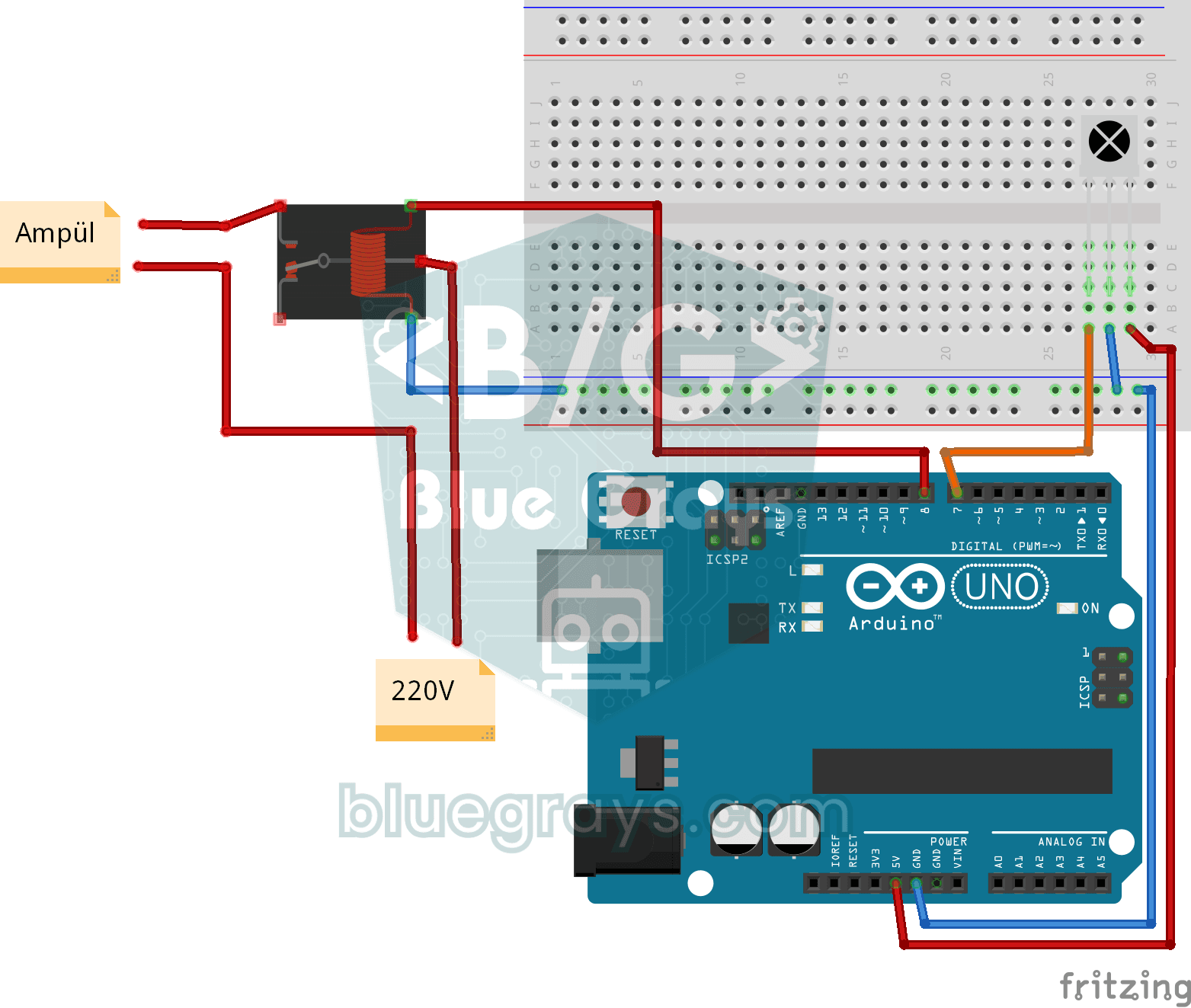
Lighting 220V Bulb with Remote Control
Switch a real light bulb in your home on and off with a TV remote, without getting up from the sofa.