
AMS1117 3.3V Regulator: Pinout, Capacitors and ESP32 Power
How do you wire an AMS1117 3.3V LDO regulator? SOT-223 pinout, 10 µF and 22 µF capacitors, 1.1 V dropout, heat calculation, ESP32 Wi-Fi current and the 7805.

AMS1117 3.3V is the most common and cheapest linear LDO regulator for turning a higher voltage such as 5 V into a steady, clean 3.3 V. The small black three-legged chip you see on ESP32 development boards, NodeMCUs, MB102 breadboard power modules and countless sensor boards is very often this one. In short: if you want to power 3.3 V parts such as the ESP32, ESP-01, nRF24L01 or BME280 from a 5 V USB or adapter rail, the AMS1117 is the first solution that comes to mind; with the right capacitors it can deliver up to 1 ampere.
But this little chip has limits: it needs about 1.1 V between input and output, it turns the excess voltage into heat, and it can oscillate if the output has no suitable capacitor. In this post you'll learn the AMS1117's pinout, capacitor choice, dropout voltage, heat calculation, whether it survives the ESP32's Wi-Fi current spikes, and how it differs from the 7805, all with real numbers. You'll also build code step by step that measures the 3.3 V rail with Arduino, ESP32 and Pico.
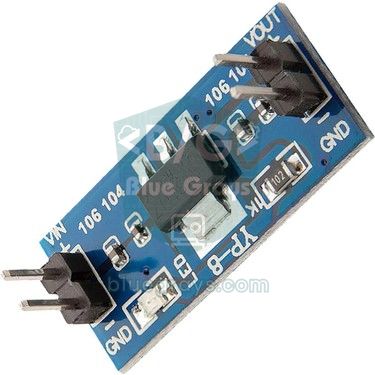
What is the AMS1117 and how does it work?
The AMS1117 is a linear regulator: inside it there is an error amplifier that constantly compares the output voltage with an internal reference, and a power transistor controlled by that amplifier. The transistor acts like a variable resistor and takes up the difference between input and output, so the output stays at 3.3 V whether the input is 4.8 V or 6 V. The name LDO (Low Dropout) comes from the fact that it can work with a smaller voltage difference than the classic 78xx series. The price is efficiency: unlike switching (buck) converters, the excess voltage times the current turns directly into heat. When making 3.3 V from 5 V, efficiency is roughly 3.3 / 5 = 66%, and this ratio is independent of current.
| Feature | AMS1117-3.3 value |
|---|---|
| Output voltage | 3.3 V fixed (tolerance about ±1.5%) |
| Other versions | 1.2 / 1.5 / 1.8 / 2.5 / 2.85 / 5.0 V and adjustable (ADJ) |
| Maximum output current | 1 A (in practice limited by heat) |
| Dropout voltage | Typically 1.1 V, at most 1.3 V (at 800 mA) |
| Maximum input voltage | 15 V (absolute limit) |
| Quiescent current | About 5 mA, at most 11 mA |
| Protection | Current limiting and thermal shutdown |
| Package | SOT-223 (most common), SOT-89, TO-252 |
| Recommended capacitors | 10 µF on the input, at least 22 µF on the output (tantalum or electrolytic) |
AMS1117 pinout and how it differs from the 7805
| Pin (text facing you, legs down) | AMS1117 (SOT-223) | LM7805 (TO-220) |
|---|---|---|
| 1 (left) | GND / ADJ | IN (input) |
| 2 (middle) | VOUT (output) | GND |
| 3 (right) | VIN (input) | OUT (output) |
| Back tab | Connected to VOUT | Connected to GND |
Why are input and output capacitors mandatory?
To stay stable, the AMS1117 needs a certain capacitance and a certain ESR (equivalent series resistance) on its output. The manufacturer's datasheet recommends at least 22 µF tantalum on the output and 10 µF on the input. With no output capacitor, or with too small a capacitance, the regulator can start oscillating when the load changes: your multimeter shows 3.3 V but the rail has hundreds of millivolts of ripple and the ESP32 resets randomly. Some old and clone AMS1117 chips can also be unstable with a single very-low-ESR ceramic capacitor, so the safest choice is tantalum or low-ESR aluminium electrolytic with a 100 nF ceramic in parallel. Place the capacitors as close to the regulator's legs as possible; even a few centimetres of jumper wire adds inductance. To understand how capacitors work, see What Is a Capacitor?.
| Location | Recommended value | Type | Purpose |
|---|---|---|---|
| Input (VIN–GND) | 10 µF | Tantalum or electrolytic, at least 16 V | Offsets the effect of the supply cable and smooths input dips |
| Input, extra | 100 nF | Ceramic | Filters high-frequency noise |
| Output (VOUT–GND) | At least 22 µF | Tantalum or low-ESR electrolytic | Mandatory for regulator stability |
| Output, extra | 100 nF | Ceramic | Handles fast current spikes of digital circuits |
| Next to the ESP32 (buffer) | 100–470 µF | Electrolytic, at least 10 V | Prevents voltage sag during Wi-Fi transmit bursts |
Dropout voltage: is getting 3.3 V from 5 V enough?
Dropout voltage tells you how much higher the input must be than the output for the regulator to still hold the output steady. For the AMS1117 this is typically 1.1 V at 800 mA and 1.3 V in the worst case; it drops a little at low current. So for a 3.3 V output the input must be at least 4.4–4.6 V. On paper 5 V is enough, but in reality a USB port varies between 4.75 and 5.25 V, a thin, long USB cable loses 0.2–0.3 V at 500 mA, and most ESP32 boards have a protection diode between USB and the regulator that drops about 0.3 V. Put together, the regulator's input can fall to 4.3 V and the output to 3.1–3.2 V. So when powering the AMS1117 from 5 V, use a short, thick cable and always measure the input. You can't get 3.3 V from a 3.7 V Li-ion battery with an AMS1117: a fully charged cell is 4.2 V, the output only reaches 3.0–3.1 V, and it drops further as the battery drains.
Heat calculation: how much current can you draw?
The power the regulator turns into heat is found with a simple formula: P = (Vin − Vout) × I. The thermal resistance of the SOT-223 package is about 60–90 °C/W depending on the copper area beneath it; in other words, every 1 W of heat raises the chip 60–90 °C above ambient. The chip works safely up to a junction temperature of about 125 °C; beyond that, thermal protection cuts the output and the circuit starts working on and off. Rule of thumb: on a small module with no extra cooling, don't exceed about 0.5–0.8 W. You can do these calculations easily with the Ohm's law calculator or the method in the calculating electrical power post.
| Input | Current | Power dissipated | Temperature rise (≈75 °C/W) | Result |
|---|---|---|---|---|
| 5 V | 100 mA | 0.17 W | ≈13 °C | Warm, no problem |
| 5 V | 250 mA | 0.43 W | ≈32 °C | Hot but safe |
| 5 V | 500 mA | 0.85 W | ≈64 °C | Very hot, needs a large copper area |
| 9 V | 150 mA | 0.86 W | ≈64 °C | Borderline |
| 12 V | 200 mA | 1.74 W | ≈130 °C | Protection kicks in, use a buck converter |
Wiring table: Arduino Uno, ESP32 and Raspberry Pi Pico
| AMS1117 / module | Arduino Uno | ESP32 | Raspberry Pi Pico |
|---|---|---|---|
| VIN (input) | 5V pin | USB 5 V or a 5 V adapter | VBUS (pin 40, USB 5 V) |
| GND | GND | GND | GND (e.g. pin 38) |
| VOUT (3.3 V) | VCC of the 3.3 V device | 3V3 pin on a bare ESP32 module without a regulator | VCC of the 3.3 V sensors |
| Measurement line | VOUT → straight to A0 | VOUT → 10k/10k divider → GPIO 34 | VOUT → 10k/10k divider → GP26 |
| Buffer capacitor | 22 µF between VOUT and GND | 100–470 µF next to the ESP32 | 22 µF between VOUT and GND |
Step-by-step setup and measuring the output voltage with Arduino
- Read the pin labels on the module or bare chip: VIN, GND, VOUT. On a bare SOT-223 the order from left to right is GND, OUT, IN.
- If you're using a bare chip, solder a 10 µF capacitor between VIN and GND and a 22 µF capacitor between VOUT and GND, close to the legs; ready-made modules usually already have them.
- With no load connected, apply 5 V to the input and measure VOUT with a multimeter: you should see a value between 3.25 and 3.35 V.
- Connect the Arduino's GND to the regulator's GND and VOUT to A0, then upload the code below.
- Connect your 3.3 V device and watch in the Serial Monitor how much the voltage drops under load.
- Run the circuit for 10 minutes and carefully check the chip's temperature; if it's too hot to touch, reduce the current or the input voltage.
1// AMS1117 çıkış gerilimi ölçer / AMS1117 output voltage monitor
2// AMS1117 VOUT -> A0, AMS1117 GND -> GND (ortak toprak / common ground)
3
4const int RAIL_PIN = A0;          // 3,3 V hattı / 3.3 V rail
5const long BANDGAP_MV = 1100L;    // dahili referans, kalibre edilebilir / internal reference, can be calibrated
6
7long readVccMv() {
8  // Referans AVcc, ölçülen kanal 1,1 V bandgap / Reference AVcc, measured channel 1.1 V bandgap
9  ADMUX = _BV(REFS0) | _BV(MUX3) | _BV(MUX2) | _BV(MUX1);
10  delay(2);                                  // referansın oturması / let the reference settle
11  ADCSRA |= _BV(ADSC);                       // dönüşümü başlat / start conversion
12  while (bit_is_set(ADCSRA, ADSC));          // bitmesini bekle / wait until done
13  uint8_t low = ADCL;                        // önce ADCL okunmalı / ADCL must be read first
14  uint8_t high = ADCH;
15  long raw = ((long)high << 8) | low;
16  return (BANDGAP_MV * 1023L) / raw;         // Vcc (mV)
17}
18
19void setup() {
20  Serial.begin(9600);
21}
22
23void loop() {
24  long vcc = readVccMv();
25  analogRead(RAIL_PIN);                      // referans değişti, ilk okumayı at / reference changed, discard first reading
26  long sum = 0;
27  for (int i = 0; i < 16; i++) {
28    sum += analogRead(RAIL_PIN);
29  }
30  float railMv = (sum / 16.0) * vcc / 1023.0;
31
32  Serial.print(F("Vcc: "));
33  Serial.print(vcc);
34  Serial.print(F(" mV | 3.3V hatti / rail: "));
35  Serial.print(railMv, 0);
36  Serial.println(F(" mV"));
37
38  if (railMv < 3200) {
39    Serial.println(F("UYARI / WARNING: 3.3V hatti dusuk / rail is low"));
40  }
41  delay(1000);
42}
The Uno's analog inputs use the 5 V rail as their reference. When powered over USB this rail can be anywhere between 4.7 and 5.1 V, so multiplying the reading directly by 5.0 gives an error of a few percent. For this reason the code first measures the processor's internal bandgap reference of about 1.1 V to find the real supply voltage (Vcc), then scales the A0 reading with that value. The bandgap value can deviate ±10% from chip to chip; if the 5 V you measure with a multimeter differs from the Vcc in the Serial Monitor, correct the BANDGAP_MV constant by the same ratio. Averaging 16 readings reduces noise. The warning threshold is set at 3200 mV because ESP32 modules work in the 3.0–3.6 V range, and a rail below 3.2 V comes dangerously close to that limit during load spikes. This code works only on AVR-based boards (Uno, Nano, Pro Mini).
Powering the ESP32 with an AMS1117: Wi-Fi current spikes
Many ESP32 DevKit boards already have an AMS1117 on them, so this chip is adequate for the ESP32 by design; the point is using it correctly. The ESP32 draws 80–150 mA on average, but during Wi-Fi transmission there are 300–500 mA current spikes lasting a few milliseconds; that's why Espressif recommends a supply that can provide at least 500 mA. The AMS1117 is fine as far as current goes; the problem is voltage headroom: at the moment of a spike the drop across the USB cable and diode grows, the regulator's input falls to its dropout limit, and the 3.3 V rail momentarily sags below the brownout threshold. The result is a "Brownout detector was triggered" message in the Serial Monitor and a board that keeps restarting; details are in the ESP32 Brownout and Guru Meditation post. The fix has three steps: a short, thick cable to the regulator's input, a 100–470 µF electrolytic buffer capacitor right next to the ESP32 on the output, and a quality adapter that holds 5 V under load too. In battery-powered projects or ones with many peripherals, a truly low-dropout LDO such as the AP2112K (600 mA, about 0.25 V dropout) or a buck converter is a more robust choice. The code below prints the reset reason at startup and continuously monitors the 3.3 V rail through a voltage divider.
1#include <Arduino.h>
2#include <esp_system.h>
3
4// 3,3 V hattı -> 10k -> GPIO34 -> 10k -> GND / 3.3 V rail -> 10k -> GPIO34 -> 10k -> GND
5const int RAIL_PIN = 34;   // ADC1, Wi-Fi açıkken de çalışır / ADC1, works with Wi-Fi on
6
7const char* resetReasonText(esp_reset_reason_t r) {
8  switch (r) {
9    case ESP_RST_POWERON:   return "Guc verildi / Power-on";
10    case ESP_RST_BROWNOUT:  return "BROWNOUT: besleme coktu / supply dropped";
11    case ESP_RST_SW:        return "Yazilim / Software restart";
12    case ESP_RST_PANIC:     return "Panic (Guru Meditation)";
13    case ESP_RST_INT_WDT:
14    case ESP_RST_TASK_WDT:
15    case ESP_RST_WDT:       return "Watchdog";
16    case ESP_RST_DEEPSLEEP: return "Deep sleep";
17    default:                return "Diger / Other";
18  }
19}
20
21void setup() {
22  Serial.begin(115200);
23  delay(500);
24  Serial.print("Reset nedeni / Reset reason: ");
25  Serial.println(resetReasonText(esp_reset_reason()));
26}
27
28void loop() {
29  uint32_t sum = 0;
30  for (int i = 0; i < 16; i++) {
31    sum += analogReadMilliVolts(RAIL_PIN);   // kalibre mV / calibrated mV
32  }
33  float railMv = (sum / 16.0f) * 2.0f;      // bölücü 1/2 / divider 1/2
34  Serial.printf("3.3V hatti / rail: %.0f mV\n", railMv);
35  if (railMv < 3200.0f) {
36    Serial.println("UYARI / WARNING: 3.3V hatti dusuk / rail is low");
37  }
38  delay(1000);
39}
The esp_reset_reason() function tells you why the ESP32 restarted; if you see ESP_RST_BROWNOUT, the problem is in the supply, not the software. For measurement, two 10 kΩ resistors are connected in series between the 3.3 V rail and GND, and the midpoint goes to GPIO 34; this puts about 1.65 V on the ADC. analogReadMilliVolts() uses the factory-calibrated ADC curve; because the ESP32 measures with its own internal reference, it can read even the rail that powers it correctly. Multiplying the result by 2 undoes the divider's effect. GPIO 34 is an ADC1 channel, so it works fine with Wi-Fi on. You can adapt the divider resistors to other values with the voltage divider calculator. The functions used work the same way on ESP32 Arduino core 2.x and 3.x.
A separate 3.3 V sensor rail with the Raspberry Pi Pico
The regulator on the Raspberry Pi Pico itself can supply about 300 mA to external circuits from the 3V3 pin. Instead of piling current-hungry parts such as an SD card module, several sensors and a wireless module onto that rail, you can feed the USB 5 V from the Pico's VBUS pin to an AMS1117 and build a separate, solid 3.3 V sensor rail. The Pico's GND and the regulator's GND must be joined. The MicroPython code below measures this rail through a 10 kΩ + 10 kΩ divider connected to GP26 (ADC0) and lights the onboard LED if the voltage falls below 3.2 V. Pin("LED") selects the onboard LED on both the Pico and Pico W. Because the Pico's ADC uses its own 3.3 V as the reference, the result should be interpreted with about ±2% accuracy.
1from machine import ADC, Pin
2import time
3
4# 3,3 V hattı -> 10k -> GP26 -> 10k -> GND / 3.3 V rail -> 10k -> GP26 -> 10k -> GND
5rail = ADC(26)              # GP26 = ADC0
6led = Pin("LED", Pin.OUT)   # dahili LED (Pico ve Pico W) / onboard LED (Pico and Pico W)
7
8def read_rail():
9    total = 0
10    for _ in range(16):
11        total += rail.read_u16()
12    raw = total / 16
13    return raw * 3.3 / 65535 * 2   # bölücü 1/2 / divider 1/2
14
15while True:
16    v = read_rail()
17    print("3.3V hatti / rail: {:.2f} V".format(v))
18    led.value(1 if v < 3.2 else 0)   # düşükse LED yanar / LED on when low
19    time.sleep(1)
AMS1117 vs 7805: what's the difference?
| Feature | AMS1117-3.3 | LM7805 |
|---|---|---|
| Output voltage | 3.3 V fixed (ADJ and 1.2–5 V versions exist) | 5 V fixed |
| Maximum current | 1 A | 1.5 A |
| Dropout voltage | About 1.1 V | About 2 V |
| Maximum input | 15 V | 35 V |
| Quiescent current | About 5 mA | About 5–8 mA |
| Package | SOT-223 (surface mount) | TO-220 (through-hole, suits a heatsink) |
| Pin order | GND, OUT, IN | IN, GND, OUT |
| Capacitors | 10 µF input, at least 22 µF output (mandatory) | 0.33 µF input, 0.1 µF output |
| Heat dissipation | 0.5–1 W with a small copper area | A few watts with a heatsink |
In short, the two chips aren't interchangeable, they complement each other. The 7805 is solid for making 5 V from a 7–12 V adapter, tolerates a high input voltage, and thanks to its TO-220 package can shed a few watts with a heatsink; but it can't make 3.3 V from 5 V, because its output is fixed at 5 V and it needs about 2 V of headroom. The AMS1117 shines at small voltage differences. If you chain the two in a 12 V system (12 V → 7805 → 5 V → AMS1117 → 3.3 V), the heat is shared between the two chips; but since both are linear, overall efficiency stays at 3.3 / 12 ≈ 27%. If the current exceeds 300 mA, making the first stage with an LM2596 buck module is both cooler and more efficient. For details on the 7805, see the 7805 Voltage Regulator post.
Project ideas with the AMS1117
- ESP-01 power board: build a small adapter with an AMS1117 and a 100 µF buffer capacitor to power the ESP-01 module from 5 V; the wiring is in the ESP-01 Module post.
- Clean nRF24L01 rail: nRF24L01 modules lose packets on a noisy supply; a separate AMS1117 and a 10 µF capacitor noticeably improve the link.
- 3.3 V sensor distribution board: power 3.3 V devices such as the BME280, MPU-6050 and OLED from a single regulator; for environmental readings see the BME280 post.
- 12 V vehicle or LED strip system: step 12 V down to 5 V with an LM2596 first, then to 3.3 V with an AMS1117 to keep the ESP32 cool.
- Your own breadboard power module: there's an AMS1117 inside the MB102 module too; you can build the same circuit permanently on perfboard.
- Voltage monitor panel: combine the measurement code in this post with an OLED display and show the 5 V and 3.3 V rails live.
Common mistakes and how to fix them
| Symptom | Likely cause | Fix |
|---|---|---|
| The output shows a value close to the input voltage instead of 3.3 V | Pins are wired wrong or the chip has burned out and shorted | Check the pin order as GND, OUT, IN and replace the chip |
| The ESP32 resets when Wi-Fi turns on | Input is at the dropout limit and there's no buffer capacitor | Use a short, thick cable, add 100–470 µF to the output and measure the 5 V rail |
| The multimeter shows 3.3 V but the circuit is unstable | The output capacitor is missing or unsuitable and the regulator is oscillating | Add a 22 µF tantalum or electrolytic and a 100 nF in parallel to the output |
| The chip is too hot to touch | The voltage difference times the current is too high | Lower the input, enlarge the copper area or use a buck converter |
| The output is around 3.0–3.1 V | The input is below 4.4 V (long USB cable, diode, battery) | Raise the input or choose a low-dropout LDO |
| The battery drains much faster than expected | The AMS1117 draws about 5 mA even at idle | Use a low-quiescent-current LDO such as the HT7333 or ME6211 |
Used with the right capacitors and respect for its heat limit, the AMS1117 is the cheapest and most practical gateway to the 3.3 V world; once you know its limits, you avoid sneaky problems such as random ESP32 resets from the start. In the BlueGrays app you can go step by step through many projects with circuit diagrams and code, from lighting an LED with the ESP32 to Wi-Fi connections, web servers and saving battery with deep sleep, and build the power supply solidly with the rules in this post.
Frequently asked questions
How many amps can the AMS1117 3.3V supply?
According to the datasheet the AMS1117 can supply at most 1 A, and its internal current limit kicks in around there. In practice heat sets the limit: drawing 500 mA from a 5 V input produces about 0.85 W in the chip, which is the real limit on small modules. For continuous use, 300–500 mA from 5 V is a safe target.
Does the AMS1117 work with 12 V?
The absolute input limit is 15 V, so 12 V won't destroy the chip right away, but the whole 8.7 V difference turns into heat. Even at 100 mA about 0.9 W is dissipated, which is too much for a small SOT-223 package. The best way is to step down to 5 V first with a buck module such as the LM2596 and then use the AMS1117.
Is the AMS1117 good enough for the ESP32?
Yes, most ESP32 development boards already use an AMS1117, and it can handle the 500 mA Wi-Fi spikes. What's required is that the input doesn't drop below 4.6 V and that there's a 100–470 µF buffer capacitor on the output near the ESP32. In battery-powered projects the dropout is too high, so a lower-dropout LDO such as the AP2112K is preferable.
Why does the AMS1117 get hot?
Because it's a linear regulator, it turns the voltage difference between input and output times the current into heat: P = (Vin − 3.3) × I. Drawing 300 mA from 5 V is about 0.5 W, and it's normal for the chip to get noticeably warm. If it's too hot to touch, reduce the current, lower the input voltage or switch to a buck converter.
Which capacitors should I use with the AMS1117?
The datasheet recommends 10 µF on the input and at least 22 µF tantalum on the output; a low-ESR aluminium electrolytic also works. The output capacitor is mandatory for stability, and without it the regulator can oscillate. Adding a 100 nF ceramic in parallel on both sides also filters high-frequency noise.
Can I get 3.3 V from a 3.7 V Li-ion battery with an AMS1117?
Not reliably. Because of the AMS1117's dropout of about 1.1 V, even a fully charged 4.2 V cell leaves the output at around 3.1 V, and it falls quickly as the battery drains. For Li-ion you should use a low-dropout LDO such as the ME6211 or AP2112K, or a buck-boost converter.
Projects to build after reading this
See all projects
LED Blink with ESP32
Teaches basic GPIO output usage with ESP32. We achieve a blinking effect by turning an LED on and off from a digital pin. ESP32 version of the classic blink project on Arduino UNO; the basic blink commands in the Arduino environment are the same, but the ESP32's pin layout and 3.3 V GPIO levels differ from those of the Arduino UNO.

ESP32 Built-in LED Blink
Blinking the built-in blue LED on the ESP32 DevKit V1. No external components required! The first project you should try when you buy an ESP32. GPIO 2 is connected to the built-in LED.

Reading Light Intensity with the ESP32 LDR Module
Real-time monitoring of the LDR module's raw ADC value and relative light percentage calculated from dark and light reference values in the Serial Monitor. This percentage is not a lux measurement. Teaches the module’s calibration logic. It is ideal to complete this before Project 10, as it is used to determine the threshold value.

ESP32 Wi-Fi STA Connection (with LCD Screen)
In this project, we connect the ESP32 to the home Wi-Fi network in Station (STA) mode in a secure, fault-tolerant manner. We store the SSID and password in a separate secrets.h file to prevent leaking to Git, set up an auto-reconnect mechanism, and display the RSSI signal level and IP address on an I2C LCD screen. The internal LED works as a status indicator. It is a production-grade connection manager.

ESP32 Asynchronous Web Server (with IP Display on LCD)
In this project, we’re turning the ESP32 into an asynchronous web server that you can control from your phone or computer on the same Wi-Fi network. Thanks to the ESPAsyncWebServer library, the server can process multiple requests simultaneously (unlike the classic WebServer.h, which blocks on a single request). You’ll be able to open the ESP32’s IP address in a browser and click the ON/OFF buttons (the /on and /off routes) to turn the LED connected to GPIO 5 on and off.

ESP32 HTTPClient + Weather API (with LCD Screen)
In this project the ESP32 makes a REST API call over the internet to a weather API (wttr.in) using HTTPClient.h. The JSON response is parsed with ArduinoJson v7, and the city, temperature, humidity, weather and wind are shown on an I2C LCD. wttr.in needs no API key; just type the name of any city.

ESP32 Deep Sleep — Battery Saving (OLED + RTC RAM Counter)
The ESP32's Deep Sleep mode shuts down the CPU and most peripherals, cutting current draw to about 10µA, which is vital for battery-powered IoT devices. This project uses three wake-up sources: a timer (15 s), an external pin (EXT0, the button on GPIO 33) and a touch pin (T0/GPIO 4). Counters marked with RTC_DATA_ATTR survive deep sleep.
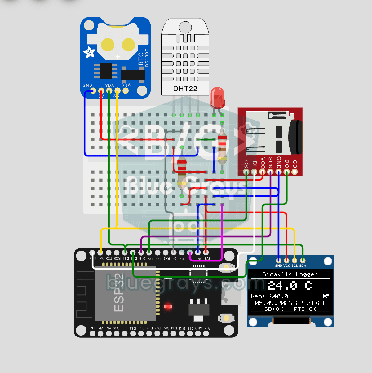
ESP32 Temperature Data Logger (DHT22 + DS1307 RTC + microSD + OLED)
Build a timed temperature and humidity logger with the ESP32! A DHT22 sensor reads temperature and humidity once a minute, and each reading is saved to a microSD card in CSV format with a real-time stamp from the DS1307 RTC module. The OLED display shows the latest temperature, humidity, timestamp and total number of records live, in large text.