
SSR Relay with Arduino: Solid State Relay and Heater Control
How do you use an SSR relay with Arduino? Mechanical relay vs SSR, AC/DC types, zero-cross, heatsink sizing, ESP32 3.3 V drive, Pico code and fake SSR tips.

An SSR relay (solid state relay) is an electronic switch that lets a microcontroller like an Arduino turn a 230 V heater, lamp, oven element or kettle on and off with a small 3–32 V signal, with no moving parts at all. In a classic relay a coil pulls a metal contact open and shut; in an SSR a light-triggered semiconductor does the job. That's why it makes no clicking sound, its contacts never wear out, it creates no sparks and it lasts for years even when switched many times a minute. For heater projects that need frequent switching, such as thermostats, incubators, sous-vide cookers and ovens, the SSR and Arduino pairing is almost the standard.
But an SSR isn't a magic box: about 1–1.6 V drops across it, which means serious heat at high currents; even when off it leaks a few milliamps; an AC-output SSR can't switch off a DC load; and a large share of cheap SSRs on the market are copies that can't carry the current printed on the label. In this post you'll learn step by step what's inside an SSR, how it differs from a mechanical relay, what the DA, DD and AA codes on the label mean, what zero-cross is, how to size a heatsink, how to control a heater safely with Arduino, ESP32 and Raspberry Pi Pico, and how to spot a fake SSR.
What is an SSR (solid state relay) and how does it work?
Inside an SSR there are two separate worlds. On the input side there's an infrared LED with a current-limiting circuit; it lights when you apply voltage to terminals 3 and 4. On the output side there's a light-sensitive trigger circuit and the power element that actually carries the load: in AC-output models a triac or two back-to-back thyristors (SCRs), in DC-output models a MOSFET. Because only light passes between input and output, the two sides are electrically isolated; the principle is the same as an optocoupler, and it typically gives 2500 V or more of isolation. So the Arduino's GND never touches the mains. In AC models the triac switches itself off the moment the current crosses zero; when you remove the input signal, the load turns off within half a cycle at most (10 ms at 50 Hz).
| Feature | Typical value (SSR-25DA class) |
|---|---|
| Input (control) voltage | 3–32 V DC |
| Input current | About 5–15 mA |
| Output (load) voltage | 24–380 V AC |
| Rated output current | 25 A (only with a proper heatsink) |
| Voltage drop when on | 1.0–1.6 V |
| Leakage current when off | A few mA (1–10 mA depending on model) |
| Isolation | 2500 V AC and above |
| Turn-on / turn-off time | ≤ 10 ms (because of zero-cross) |
| Terminals | 1–2: load, 3 (+) and 4 (−): control input |
The difference between an SSR and a mechanical relay
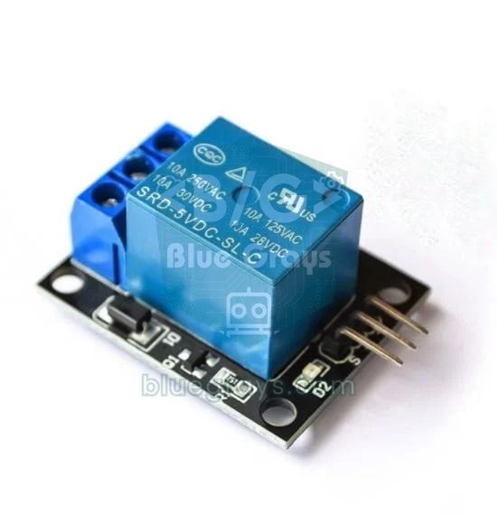
| Feature | Mechanical relay | SSR (solid state relay) |
|---|---|---|
| Switching element | Coil + metal contact | Triac, thyristor or MOSFET |
| Sound | Clicks | Silent |
| Lifespan | About 100,000 switchings under load | Practically unlimited switching |
| Sparks and noise | Arcing as the contact opens | Very low with zero-cross models |
| Loss when on | Very low (milliohm-level contact) | 1–1.6 V drop, heats up |
| Leakage when off | None, full separation | A few mA of leakage current |
| AC and DC | Switches both | Only AC or only DC, depending on type |
| Control current | 70–90 mA for the coil (via a module) | 5–15 mA, can connect straight to a pin |
| Failure mode | Contact may stick or stay open | Usually shorts, meaning permanently on |
| Price | Cheap | More expensive, plus a heatsink |
DA and AA types: what do DA, DD and AA on an SSR label mean?
The two-letter code on an SSR label tells you the input type first, then the output type. D stands for DC and A stands for AC. So an SSR-25DA is not a "DC relay"; it's a relay that is controlled by DC and switches an AC load, and it's the type used most in Arduino projects. An SSR-25DD is controlled by DC and switches a DC load (for example a 12 V heater pad or pump). An SSR-25AA needs mains voltage on its input too; it isn't used directly with a microcontroller and is mostly chosen when a thermostat or switch drives a large load. If you're confused, the post on the difference between AC and DC current will refresh the basics.
| Label code | Input (control) | Output (load) | Typical use |
|---|---|---|---|
| DA (e.g. SSR-25DA) | 3–32 V DC | 24–380 V AC | 230 V heater, lamp or oven with Arduino |
| DD (e.g. SSR-25DD) | 3–32 V DC | 5–60 V DC (varies by model) | 12/24 V heater pad, pump, LED strip |
| AA (e.g. SSR-25AA) | 90–250 V AC | 24–380 V AC | Driving a large AC load with a switch or thermostat |
| G3MB-202P module | 5 V DC | 100–240 V AC, max 2 A | Small AC loads: lamp, small fan |
What is zero-cross and why does it matter?
Mains voltage is a 50 Hz sine wave and crosses zero every 10 ms. When you give a zero-cross SSR a turn-on signal, it doesn't switch the output on immediately; it waits for the first moment the voltage approaches zero. So a heater or incandescent lamp turns on near zero rather than at the voltage peak of about 325 V; the inrush current, electromagnetic noise and buzzing are greatly reduced. That's perfect for resistive loads. The price: you can't dim a lamp with phase-angle control using a zero-cross SSR; for that you need "random turn-on" models that switch immediately. For the same reason, the Arduino's 490 Hz analogWrite signal is meaningless for an SSR, because the signal changes several times in each half-cycle and the result is random (see the PWM post to learn why frequency matters). The right way to adjust a heater's power is time-proportional control: for example, keep it on for 1.2 s and off for 0.8 s of a 2-second window to get 60% power. Since 2 seconds is 200 half-cycles, this method has a resolution of about 0.5%.
Heatsink needs: how hot does an SSR get?
A mechanical relay's contact has almost zero resistance, but an SSR's triac drops about 1.2–1.6 V while conducting. The power dissipated is roughly P = Vdrop × I. A 2000 W heater draws I = 2000 / 230 ≈ 8.7 A at 230 V; assuming 1.3 V drops across the SSR, P ≈ 1.3 × 8.7 ≈ 11 W of heat is released. That's enough to heat a small soldering iron tip, and an SSR body without a heatsink reaches dangerous temperatures within minutes. Since the plastic case alone can handle only around 2–3 W, the practical limit without a heatsink is about 2 A. Screw the SSR to an aluminium heatsink with a thin layer of thermal paste, make sure the metal base doesn't exceed 80 °C, and choose a generous current rating: the SSR's rated current should be at least 2 times the load current for resistive loads, and 3–4 times for inductive loads such as motors and transformers. For power and current calculations you can use the Ohm's law calculator and the electrical power calculation post.
| Load current (230 V) | Example load | Heat in the SSR (≈1.3 V) | Cooling recommendation |
|---|---|---|---|
| 0.5 A | 100 W incandescent lamp | ≈ 0.7 W | No heatsink needed |
| 2 A | 450 W heater | ≈ 2.6 W | Borderline; a small heatsink is recommended |
| 4.3 A | 1000 W heater | ≈ 5.6 W | Medium heatsink (≈ 5 °C/W or better) |
| 8.7 A | 2000 W heater | ≈ 11 W | Large heatsink (≈ 2.5 °C/W) and at least a 25 A SSR |
| 13 A | 3000 W heater | ≈ 17 W | Fan-cooled heatsink and a genuine-brand 40 A SSR |
SSR wiring: Arduino Uno, ESP32 and Raspberry Pi Pico
| Connection | Arduino Uno | ESP32 | Raspberry Pi Pico |
|---|---|---|---|
| Control pin | D8 | GPIO 26 | GP15 |
| SSR input + (3) | Directly to D8 | 5V/VIN (via transistor) | VBUS (via transistor) |
| SSR input − (4) | GND | NPN collector | NPN collector |
| NPN base (BC547 / 2N2222) | - | 1 kΩ to GPIO 26, 10 kΩ to GND | 1 kΩ to GP15, 10 kΩ to GND |
| NPN emitter | - | GND | GND |
| DS18B20 data | D2 | GPIO 4 | GP16 |
| DS18B20 VCC | 5V | 3V3 | 3V3(OUT) |
| 4.7 kΩ pull-up | Data – 5V | Data – 3V3 | Data – 3V3 |
Because the Arduino Uno's pins output 5 V and easily supply up to 20 mA, you can connect the input of an SSR-DA directly between D8 and GND; the input has a built-in current limiter, so no extra resistor is needed. The ESP32 and Pico run at 3.3 V. Even if the label says "3–32 V DC", 3.3 V is very close to the bottom of that range; when the pin sags to 3.1 V under load, or with a copy SSR that needs a higher input voltage, the relay sometimes triggers and sometimes doesn't. On top of that, the Pico's pins are configured by default for only about 4 mA. So on 3.3 V boards the most reliable way is to drive the SSR from 5 V through an NPN transistor: the GPIO goes to the transistor's base through a 1 kΩ resistor, the SSR's + terminal goes to 5 V, its − terminal to the collector, and the emitter to GND. When the GPIO goes HIGH the transistor conducts and the SSR sees about 4.8 V. A 10 kΩ resistor between the base and GND stops the heater from turning on by itself when the pin floats while the board powers up or restarts. All GNDs must be common; you can find out why in the common GND post.
- First disconnect the mains completely: unplug it or switch off the breaker, and make sure there's no voltage on the terminals.
- Screw the SSR to the heatsink with a thin layer of thermal paste; connect the heatsink and the metal enclosure to protective earth (yellow-green wire).
- Wire the control side: connect terminals 3 (+) and 4 (−) to the Arduino or the transistor according to the table above, upload the code with no mains connected and watch the LED on the SSR blink.
- On the load side, connect the live wire (brown) to terminal 1 of the SSR and terminal 2 to the heater; the neutral (blue) goes straight to the heater. Put a fuse rated for the load current on the live line.
- Choose the cable cross-section for the current: at least 1.5 mm² up to 10 A, 2.5 mm² for 16 A; fit ferrules on stranded wires and tighten the screws firmly.
- Connect a thermal fuse or bimetal thermostat that works independently of the Arduino in series with the heater; it's the last line of defence if the SSR fails short.
- Place all the mains part in a covered, insulated enclosure; don't power it up before closing the enclosure or without a supply line protected by a residual-current device (RCD).
Heater control with Arduino: a time-proportional thermostat
The program below measures with a DS18B20 temperature sensor and adjusts the heater's power using 2-second time windows. The target is 40 °C and the proportional band is 5 °C: at 35 °C and below the heater runs at 100%, at 37.5 °C at 50%, and at 40 °C at 0%. This reduces the big overshoot of simple on-off thermostats. The code doesn't use delay(); measurement and window timing are done with millis(), and the sensor's roughly 750 ms conversion completes in the background without waiting. If the sensor is disconnected (-127 °C) or the temperature exceeds the 70 °C safety limit, the heater is switched off immediately. For sensor wiring details see the DS18B20 temperature sensor post; to compile the code, install the OneWire and DallasTemperature libraries from the Library Manager.
1#include <OneWire.h>
2#include <DallasTemperature.h>
3
4const uint8_t SSR_PIN = 8;              // SSR giriş + (3) / SSR input + (3)
5const uint8_t ONE_WIRE_PIN = 2;         // DS18B20 veri / DS18B20 data
6const float HEDEF_C = 40.0;             // hedef sıcaklık / target temperature
7const float BANT_C = 5.0;               // oransal bant / proportional band
8const float EMNIYET_C = 70.0;           // üst güvenlik sınırı / safety cutoff
9const unsigned long PENCERE_MS = 2000;  // zaman penceresi / time window
10
11OneWire oneWire(ONE_WIRE_PIN);
12DallasTemperature sensors(&oneWire);
13
14unsigned long pencereBasi = 0;
15unsigned long sonOlcum = 0;
16unsigned long acikSure = 0;             // pencere içindeki açık süre / on-time in window
17
18void setup() {
19  pinMode(SSR_PIN, OUTPUT);
20  digitalWrite(SSR_PIN, LOW);           // açılışta ısıtıcı kapalı / heater off at start
21  Serial.begin(9600);
22  sensors.begin();
23  sensors.setWaitForConversion(false);  // bloklamadan ölç / non-blocking conversion
24  sensors.requestTemperatures();        // ilk ölçümü başlat / start first conversion
25}
26
27void loop() {
28  unsigned long simdi = millis();
29
30  if (simdi - sonOlcum >= 1000) {       // saniyede bir ölç / measure once per second
31    sonOlcum = simdi;
32    float t = sensors.getTempCByIndex(0);
33    sensors.requestTemperatures();      // sonraki ölçümü başlat / start next conversion
34
35    float oran = 0.0;                   // güç oranı 0..1 / power ratio 0..1
36    if (t != DEVICE_DISCONNECTED_C && t < EMNIYET_C) {
37      oran = constrain((HEDEF_C - t) / BANT_C, 0.0, 1.0);
38    }
39    acikSure = (unsigned long)(oran * PENCERE_MS);
40
41    Serial.print(F("Sicaklik / Temp: "));
42    Serial.print(t, 1);
43    Serial.print(F(" C  Guc / Power: %"));
44    Serial.println(oran * 100.0, 0);
45  }
46
47  if (simdi - pencereBasi >= PENCERE_MS) {
48    pencereBasi += PENCERE_MS;          // yeni pencere / new window
49  }
50  digitalWrite(SSR_PIN, (simdi - pencereBasi < acikSure) ? HIGH : LOW);
51}
SSR with ESP32: 3.3 V drive and a thermostat with hysteresis
On the ESP32 let's look at a different method: on-off control with hysteresis. The heater turns on when the temperature drops below 39 °C and turns off above 41 °C; the 2 °C dead band stops the SSR from switching on and off constantly because of small fluctuations in the sensor. The SSR is driven from 5 V through an NPN transistor connected to GPIO 26, as in the table. We chose GPIO 26 on purpose: GPIO 0, 2, 5, 12 and 15 are pins that determine the board's boot behaviour at startup, and a load connected to them can be triggered unintentionally at power-up. The code compiles the same on ESP32 Arduino core 2.x and 3.x; if you use core 3.x, just install version 2.3.8 or newer of the OneWire library. As a next step you can take this thermostat onto Wi-Fi and set the target temperature from your phone via Home Assistant.
1#include <OneWire.h>
2#include <DallasTemperature.h>
3
4const int SSR_PIN = 26;            // NPN tabanına 1 kΩ ile / to NPN base via 1 kΩ
5const int ONE_WIRE_PIN = 4;        // DS18B20 veri / DS18B20 data
6const float HEDEF_C = 40.0;        // hedef sıcaklık / target temperature
7const float HISTEREZIS_C = 1.0;    // ±1 °C ölü bant / ±1 °C dead band
8const float EMNIYET_C = 70.0;      // güvenlik sınırı / safety cutoff
9
10OneWire oneWire(ONE_WIRE_PIN);
11DallasTemperature sensors(&oneWire);
12
13bool isitici = false;
14unsigned long sonOlcum = 0;
15
16void setup() {
17  pinMode(SSR_PIN, OUTPUT);
18  digitalWrite(SSR_PIN, LOW);      // açılışta kapalı / off at start
19  Serial.begin(115200);
20  sensors.begin();
21}
22
23void loop() {
24  if (millis() - sonOlcum < 1000) return;
25  sonOlcum = millis();
26
27  sensors.requestTemperatures();   // yaklaşık 750 ms bekler / waits about 750 ms
28  float t = sensors.getTempCByIndex(0);
29
30  if (t == DEVICE_DISCONNECTED_C || t >= EMNIYET_C) {
31    isitici = false;               // arıza ya da aşırı sıcaklık / fault or overheat
32  } else if (t < HEDEF_C - HISTEREZIS_C) {
33    isitici = true;                // soğuk: ısıt / cold: heat
34  } else if (t > HEDEF_C + HISTEREZIS_C) {
35    isitici = false;               // sıcak: kapat / hot: switch off
36  }
37  digitalWrite(SSR_PIN, isitici ? HIGH : LOW);
38
39  Serial.printf("Sicaklik / Temp: %.1f C  SSR: %s\n", t, isitici ? "ACIK / ON" : "KAPALI / OFF");
40}
SSR control with Raspberry Pi Pico and MicroPython
On the Raspberry Pi Pico, the onewire and ds18x20 modules come built into MicroPython; you don't need to copy any extra files. The code below is the same time-proportional control as the Arduino example: the DS18B20 is on GP16, and the base of the transistor driving the SSR is connected to GP15 through a 1 kΩ resistor. Connect the SSR's + terminal to the VBUS pin (physical pin 40), which outputs 5 V when the Pico is powered over USB. For timing, time.ticks_ms() and time.ticks_diff() are used; since these functions give the correct difference even when the counter wraps around, they're safe in a thermostat that runs for a long time. If the sensor isn't found or a read fails, the power ratio is set to zero, so the heater stays off. If you're using the Pico for the first time, see What Is the Raspberry Pi Pico for MicroPython setup.
1from machine import Pin
2import onewire, ds18x20, time
3
4ssr = Pin(15, Pin.OUT, value=0)                       # NPN tabanı (1 kΩ) / NPN base (1 kΩ)
5sensor = ds18x20.DS18X20(onewire.OneWire(Pin(16)))    # DS18B20 veri / DS18B20 data
6roms = sensor.scan()
7
8HEDEF_C = 40.0      # hedef sıcaklık / target temperature
9BANT_C = 5.0        # oransal bant / proportional band
10EMNIYET_C = 70.0    # güvenlik sınırı / safety cutoff
11PENCERE_MS = 2000   # zaman penceresi / time window
12
13def olcum_baslat():
14    try:
15        sensor.convert_temp()                         # dönüşümü başlat / start conversion
16    except Exception:
17        pass                                          # sensör yok / no sensor
18
19oran = 0.0
20son_olcum = time.ticks_ms()
21pencere_basi = time.ticks_ms()
22olcum_baslat()
23
24while True:
25    simdi = time.ticks_ms()
26    if time.ticks_diff(simdi, son_olcum) >= 1000:     # saniyede bir / once per second
27        son_olcum = simdi
28        try:
29            t = sensor.read_temp(roms[0])
30            if t >= EMNIYET_C:
31                oran = 0.0                            # aşırı sıcaklık / overheat
32            else:
33                oran = min(max((HEDEF_C - t) / BANT_C, 0.0), 1.0)
34            print("Sicaklik / Temp: {:.1f} C  Guc / Power: %{:.0f}".format(t, oran * 100))
35        except Exception:
36            oran = 0.0                                # hata: ısıtıcı kapalı / error: heater off
37            print("Sensor hatasi / Sensor error")
38        olcum_baslat()                                # sonraki ölçüm / next conversion
39    if time.ticks_diff(simdi, pencere_basi) >= PENCERE_MS:
40        pencere_basi = time.ticks_add(pencere_basi, PENCERE_MS)   # yeni pencere / new window
41    ssr.value(1 if time.ticks_diff(simdi, pencere_basi) < oran * PENCERE_MS else 0)
Fake SSR warning: why does a relay labelled 40 A burn out?
A large share of the cheap SSRs on the market are copies imitating the look of a well-known brand. Inside many teardowns of fake 40 A relays, a small 12–16 A triac turns up; some have no zero-cross circuit or output snubber, and the input-output isolation is far lower than what's printed on the label. These relays overheat even at a few amps, the plastic case softens and they usually fail short, so the heater never turns off again. That's why you should never treat the SSR as the only safety element in a heater project. You can recognise a fake SSR by these signs:
- Price and weight: it's several times cheaper than genuine-brand SSRs and feels noticeably lighter in the hand.
- Same case, different current: 10 A, 25 A and 40 A versions are sold in exactly the same size, at the same price and with the same weight.
- Printing and label flaws: a faded or misaligned logo, a misspelled brand name, or no serial number or production date.
- Potting compound: the filling on the underside is uneven, bubbly or partly empty.
- Heat test: under load, measure the temperature of the metal base with a thermometer during the first hour; if it quickly passes 60 °C even at half the rated current, don't trust the relay.
- The safe solution: buy well-known brands such as Omron, Crydom, Carlo Gavazzi or Schneider from a reliable seller; use an SSR of unknown origin at no more than a quarter of its rated current.
Project ideas with an SSR
- Smart thermostat: keep a room heater at the target temperature; see the Arduino thermostat post for the basic logic.
- Sous-vide and yoghurt maker: combine time-proportional control with PID control to hold the water steady within ±0.5 °C.
- Incubator: hold 37.5 °C stable for days; add a second sensor for humidity monitoring.
- Mini reflow oven: heat a small electric oven to a solder profile with a MAX6675 thermocouple and an SSR.
- Smart plug: switch 230 V appliances on and off from your phone with an ESP32; details in the ESP32 smart plug post.
- Pipe and greenhouse heater: use a frost alarm to switch on the heating cable when the temperature falls to 2 °C.
Common mistakes and how to fix them
| Symptom | Likely cause | Fix |
|---|---|---|
| The SSR's LED is on, but the load doesn't work | The load circuit is open, the fuse has blown, or the load current is below the SSR's minimum current | Check the live and neutral lines; use a mechanical relay for very small loads |
| The load never turns off | An AC-output SSR is driving a DC load, or the SSR has failed short | Use a DD-type SSR or a MOSFET for DC; replace the faulty SSR |
| An LED bulb glows faintly or flickers when off | The SSR's leakage current | Add a suitable load resistor in parallel with the load, or choose a mechanical relay for this load |
| The multimeter shows 230 V at the output of an off SSR | Normal with no load attached, because of leakage current | Take the measurement with the load connected |
| The SSR and heatsink get very hot | Heatsink too small, no thermal paste, current too high, or the SSR is fake | Use a bigger heatsink, recalculate the current, use a genuine-brand SSR |
| Sometimes doesn't trigger with ESP32 or Pico | 3.3 V sits at the bottom of the input range | Drive the SSR from 5 V through an NPN transistor |
| The heater runs for a moment while the board powers up | The pin floats at startup, or a boot pin was chosen | Add a 10 kΩ pull-down, use a safe pin like GPIO 26 |
| Power control with analogWrite is inconsistent | A zero-cross SSR can't follow fast PWM | Use a 1–2 second time-proportional window |
Chosen correctly and cooled well, an SSR is the quietest and longest-lasting way to control a heater in Arduino projects; just pick an SSR that matches the load type, calculate the current generously, be careful about fake relays and always add an independent thermal protection. If you'd like to understand relay logic and temperature measurement step by step first, in the BlueGrays app you can explore projects such as switching a 220 V bulb with a button and a remote control, ESP32 smart lighting and temperature measurement, with circuit diagrams and code.
Frequently asked questions
Can an SSR relay be connected directly to an Arduino?
Yes. With a DC-input SSR such as the SSR-25DA, you can connect terminal 3 (+) to a digital pin of the Arduino and terminal 4 (−) to GND; since the input draws only 5–15 mA and has a built-in current limiter, no extra resistor is needed. The load side is completely isolated from the Arduino and must be wired separately according to mains regulations.
Does an SSR relay work with 3.3 V?
Most SSRs with a 3–32 V input trigger at 3.3 V, but this value is very close to the lower limit and isn't reliable, especially with copy relays. When using an ESP32 or Raspberry Pi Pico, driving the SSR from 5 V through an NPN transistor such as a BC547 or 2N2222 is the most robust solution.
Why does an SSR get hot, and is a heatsink a must?
About 1–1.6 V drops across an SSR when it conducts, and multiplied by the current this voltage turns into heat; at 10 A that's about 13 W. An SSR without a heatsink generally works safely up to around 2 A; at higher currents an aluminium heatsink mounted with thermal paste is essential.
Can you control a DC motor or LED strip with an SSR?
Only with a DC-output (DD-type) SSR. AC-output SSRs labelled DA or AA use a triac and, once switched on in DC, never turn off. For low-voltage DC loads, a logic-level MOSFET is often a cheaper and more efficient choice.
Can you dim a lamp with a zero-cross SSR?
No. A zero-cross SSR can only turn on when the voltage is near zero, so it can't do phase-angle control; the lamp either lights fully or flickers. For dimming you need a random turn-on SSR with a zero-cross detector circuit, or a ready-made AC dimmer module; for heaters, time-proportional control with a zero-cross SSR is the right method.
Why do I measure voltage at the output of an off SSR?
Even when off, SSRs pass a few milliamps of leakage current because of the snubber circuit at the output and the structure of the semiconductor. With no load connected, a multimeter's high input resistance shows almost the full mains voltage from this tiny current; that's normal. But for this reason, never use an SSR as a safety isolator, and always unplug before maintenance.
Projects to build after reading this
See all projects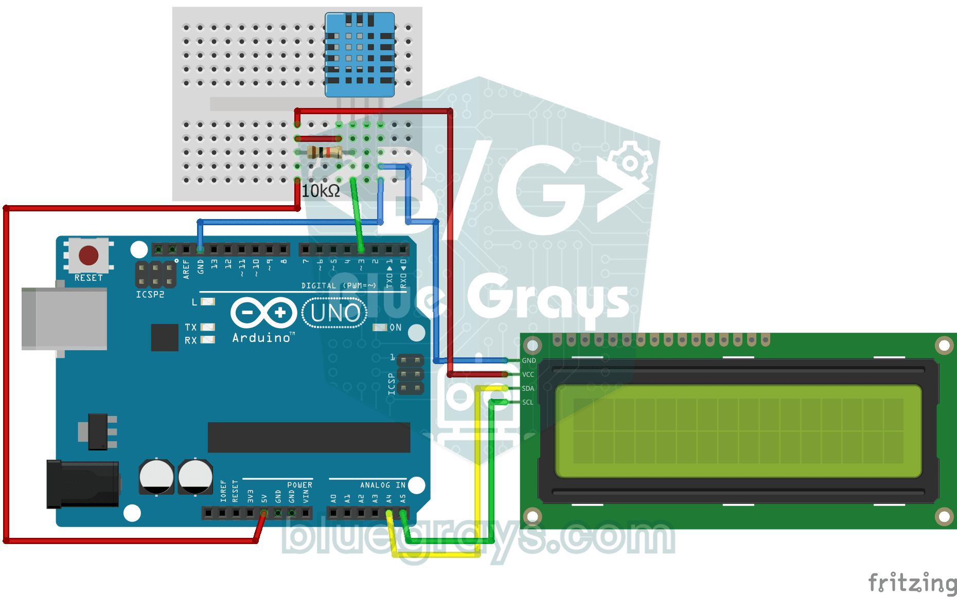
Temperature and Humidity with DHT11
How warm is your room, and is the air humid or dry? The DHT11 sensor measures temperature and humidity, and the Arduino writes the values on a two-line LCD screen, refreshing every couple of seconds.
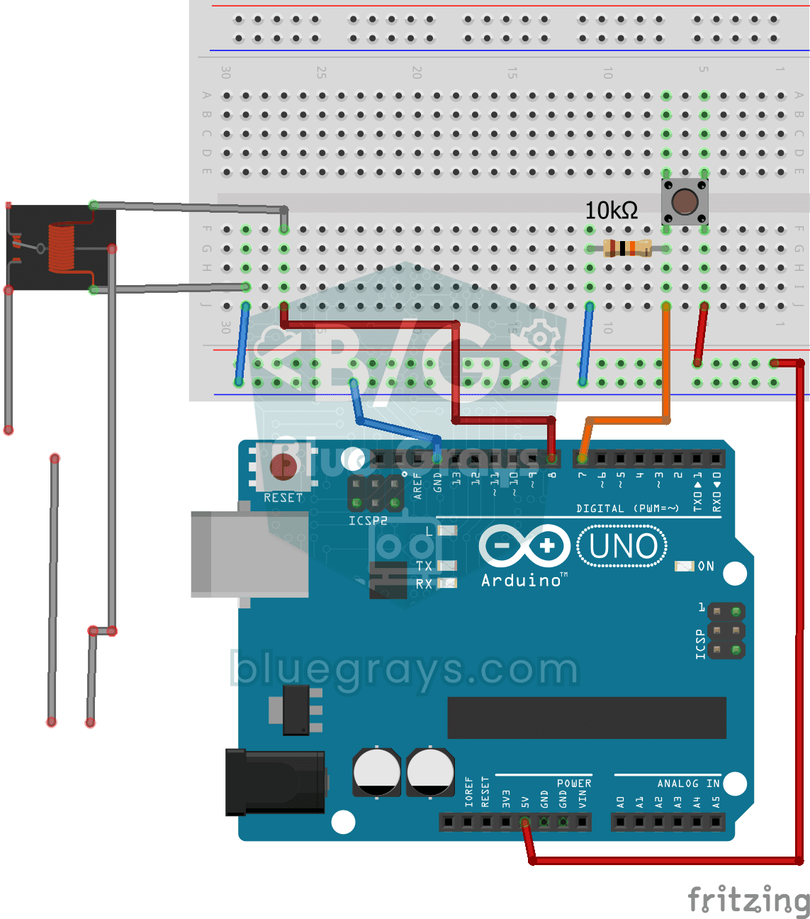
Lighting 220V Bulb with Push Button
As long as you hold the button, a real 220-volt bulb stays lit, and it goes out the moment you let go.
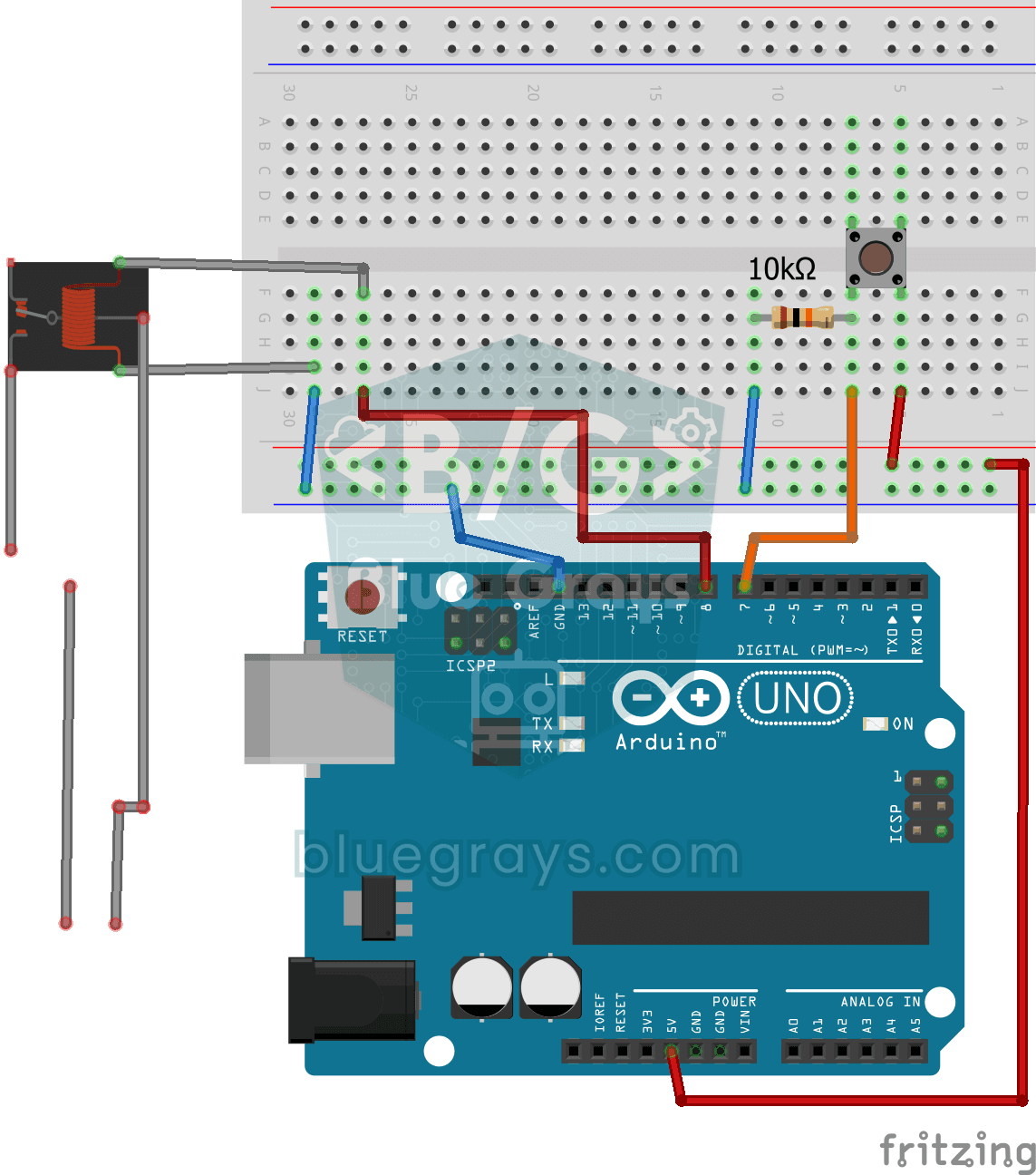
Lighting 220V Bulb with Button (On-Off)
Want to switch a real household bulb on and off with a tiny button? Each time you press the button, the Arduino flips a relay and the bulb lights up; press again and it goes off.
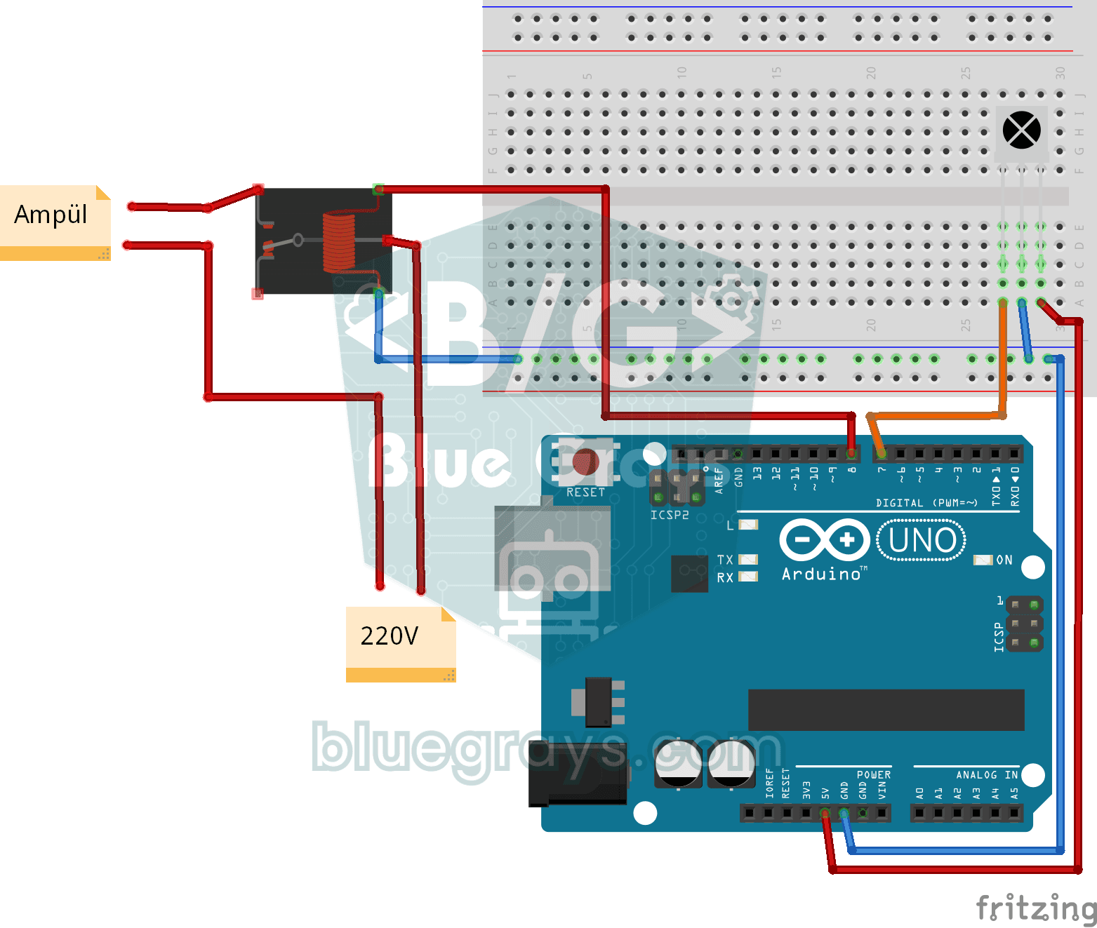
Lighting 220V Bulb with Remote Control
Switch a real light bulb in your home on and off with a TV remote, without getting up from the sofa.
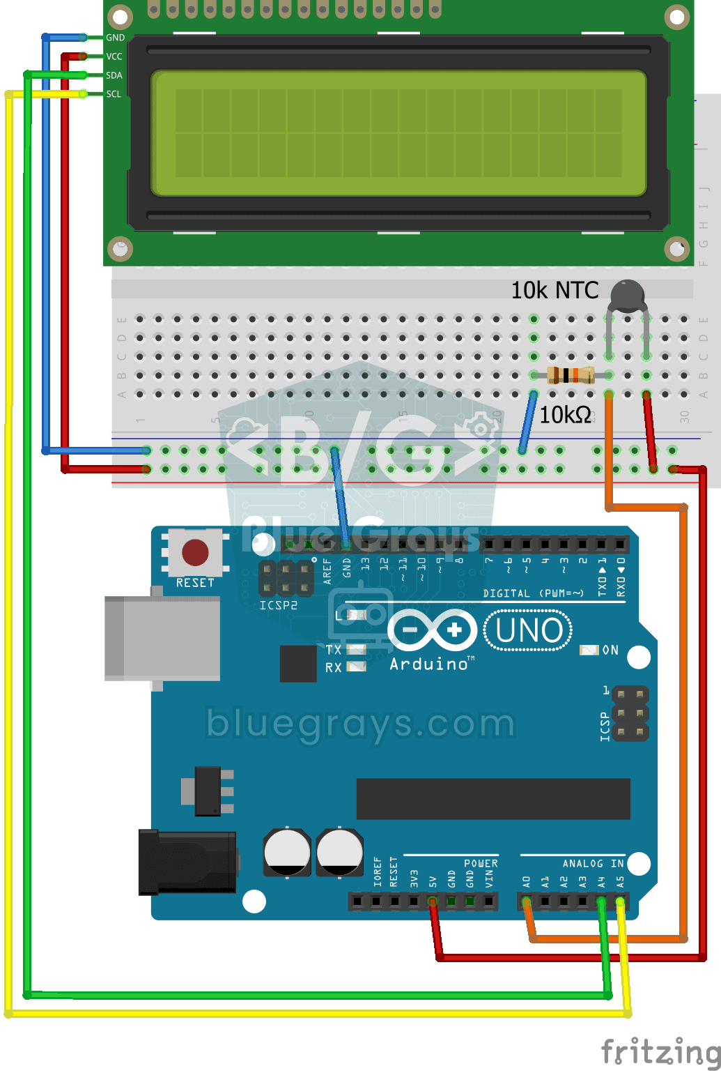
Temperature Measurement with NTC and 2x16 Lcd Display
Measure the temperature around you with a sensor that looks like a tiny bead. This part, called an NTC, lets electricity through more easily as it warms up; the Arduino reads that change, turns it…

ESP32 DHT22 Temperature and Humidity (with LCD Display)
This project measures ambient temperature and humidity using a DHT22 sensor and displays the data in real time on a 16x2 I2C LCD. Data is read from the sensor using the one-wire protocol via the Adafruit DHT library. This project serves as the foundation for IoT weather stations, smart home automation, or environmental monitoring systems in greenhouses. Communication with the DHT22 is established via the ESP32's GPIO 4 pin.

ESP32 Smart Lighting (PIR + LDR + Relay + OLED)
With an ESP32, a PIR motion sensor, an LDR light sensor and a relay module, we turn your hallway, bathroom or pantry into smart lighting. If the room is already bright, the light stays off even when there is motion, so it never wastes energy during the day. The light stays on for 30 seconds, and the time extends automatically while motion continues.

Smart Stair and Corridor Lighting
Step onto the stairs or into the hallway and the lights come on one step at a time in the direction you are walking.