
Music Reactive LED Arduino: WS2812B VU Meter Project
Music reactive LED project: build a VU meter on a WS2812B ring with Arduino Uno + KY-038 or ESP32 + INMP441. Wiring, ready code, threshold tuning, noise filtering.

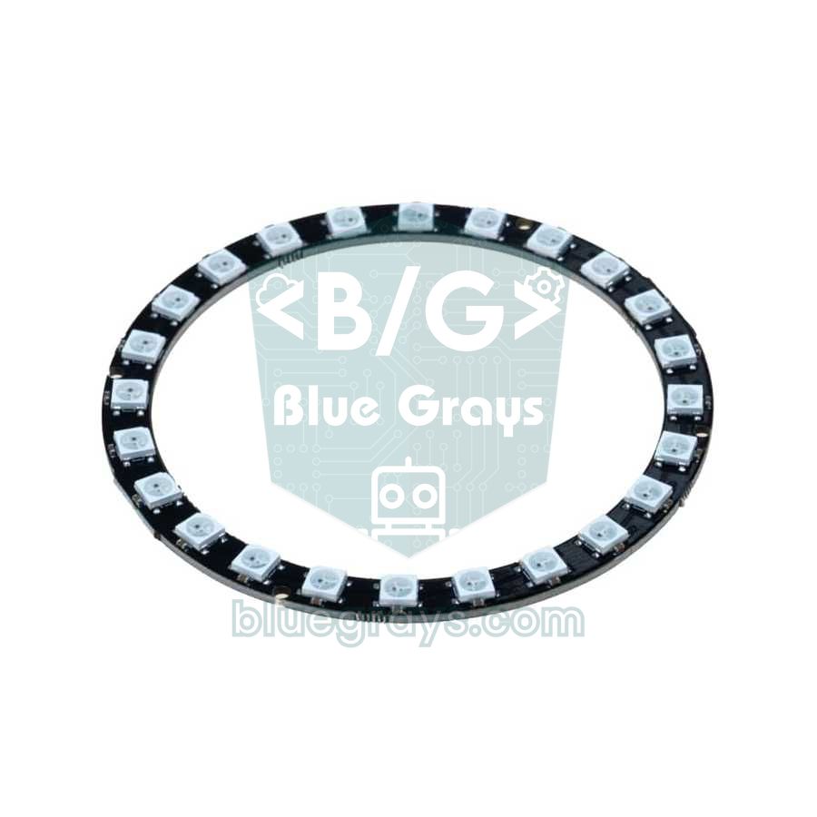
A music reactive LED Arduino project listens to the sound around you with a microphone and lights more LEDs the louder it gets, imitating the VU meter on old hi-fi systems. In this guide you'll use a 24-LED WS2812B ring (the same code works on a strip) to build two versions: a cheap, quick one with an Arduino Uno and a KY-038 sound sensor, and a much cleaner-measuring one with an ESP32 and an INMP441 I2S digital microphone.
The real trick of the project isn't lighting LEDs, it's measuring sound correctly. The microphone signal is a wave that changes direction thousands of times per second, so a single analogRead value tells you nothing. That's why you'll learn step by step how to measure amplitude over a time window, find the noise floor of a quiet room automatically, adjust sensitivity with a potentiometer, and use a smoothing filter that removes flicker.
How does a music reactive LED work?
The chain has four links: the microphone turns sound into an electrical signal, the microcontroller samples that signal, a single sound level number is calculated from the samples, and that number is converted into how many LEDs to light. There are two common ways to calculate the level. The peak-to-peak method takes the difference between the largest and smallest values in a short time; it's simple and enough for the Uno. The RMS method takes the square root of the average of the squared samples and gives the real energy of the sound. Because the human ear perceives loudness logarithmically rather than linearly, converting the RMS value to decibels (dB = 20 × log10(RMS)) gives a much more natural VU meter movement. We'll use that in the ESP32 version.
| Feature | Uno + KY-038 | ESP32 + INMP441 |
|---|---|---|
| Microphone type | Analog electret, no amplifier | Digital MEMS, I2S output |
| Resolution | 10-bit ADC (4.9 mV step) | 24-bit data |
| Sampling | About 8.9 kHz (analogRead ~112 µs) | 16 kHz, continuous with DMA |
| Level calculation | Peak-to-peak | RMS + decibels |
| Sensitivity | Low, reacts to loud and close sounds | High, easily picks up room music |
| Noise | Affected by supply noise | Very low, digital line |
| Difficulty | Beginner | Intermediate |
Components you need
- Microcontroller: an Arduino Uno (or Nano) or an ESP32 development board.
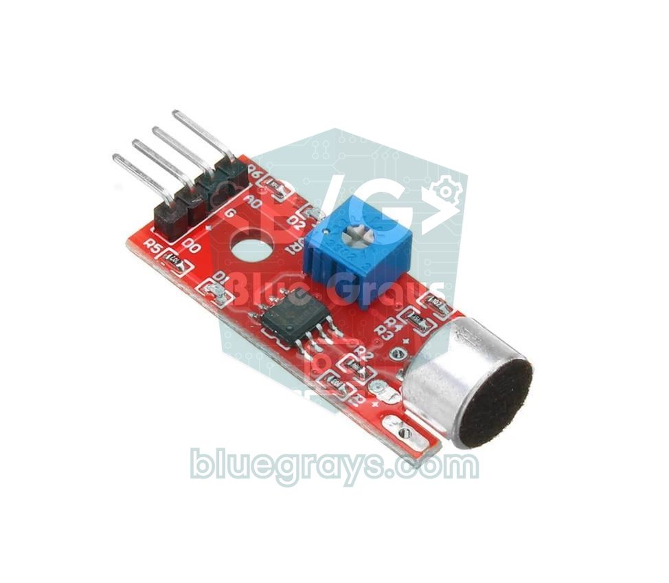
- Microphone: a KY-038 sound sensor module for the Uno, an INMP441 I2S microphone module for the ESP32.
- LEDs: a 24-LED WS2812B ring or a 30–60 LED WS2812B strip.
- 330 Ω resistor: in series with the LED data line; it prevents signal reflections and damage to the first LED.
- 1000 µF / 10 V capacitor: across the 5V and GND of the LED supply; it smooths sudden current spikes.
- 10 kΩ potentiometer: for setting sensitivity (full scale) in the Uno version.
- 5 V 2 A power adapter: essential if you use more than 24 LEDs or raise the brightness.
- A breadboard and jumper wires.
Uno + KY-038 wiring
| Part / pin | Arduino Uno | Note |
|---|---|---|
| KY-038 + | 5V | Module supply |
| KY-038 G | GND | Common ground |
| KY-038 AO | A0 | Analog sound signal |
| KY-038 DO | Unconnected | Not used in the VU meter |
| Potentiometer middle pin | A1 | Outer pins to 5V and GND |
| WS2812B DIN | D6 (through 330 Ω) | Input (DI) side of the ring |
| WS2812B 5V | 5V or external 5 V | 1000 µF capacitor between 5V and GND |
| WS2812B GND | GND | Must be common with the external supply |
Measuring sound amplitude: the peak-to-peak method
The KY-038's AO output is a signal that sits steady at about 2.5 V in silence and swings above and below that value as sound arrives. On the Uno, analogRead reads this midpoint as a number around 500. A single reading gives a random value depending on which moment of the wave it lands on. So we read over a 25-millisecond window and store the largest and smallest values. Because one analogRead on the Uno takes about 112 microseconds, roughly 220 samples are taken in 25 ms; that's enough to catch at least a few full waves of bass and mid frequencies. At the end of the window, maximum minus minimum is the current sound level. Since the KY-038 has no amplifier, this difference is 2–5 in a quiet room and 50–200 with loud music playing nearby.
Step-by-step Uno version
- Open the Library Manager in the Arduino IDE, search for the Adafruit NeoPixel library and install it.
- Build the circuit using the table above; connect the capacitor's long leg (+) to 5V.
- Upload the code below and keep the room quiet for the first half second: the code measures the noise floor during that time.
- Open the Serial Monitor at 115200 baud and look at the noise floor value it prints; if it's above 10, there's supply noise.
- Play music and turn the potentiometer to find the point where the ring almost fills completely at the loudest volume.
- Place the microphone 20–50 cm from the speaker, away from the LED light and table vibration.
1#include <Adafruit_NeoPixel.h>
2
3#define LED_PIN    6     // WS2812B DIN / WS2812B DIN
4#define NUM_LEDS   24    // halkadaki LED sayısı / number of LEDs in the ring
5#define MIC_PIN    A0    // KY-038 AO / KY-038 AO
6#define POT_PIN    A1    // hassasiyet potu / sensitivity pot
7#define WINDOW_MS  25    // ölçüm penceresi (ms) / measurement window (ms)
8
9Adafruit_NeoPixel strip(NUM_LEDS, LED_PIN, NEO_GRB + NEO_KHZ800);
10
11int noiseFloor = 0;          // sessizlikteki genlik / amplitude in silence
12float level = 0;             // yumuşatılmış seviye / smoothed level
13int peakLed = 0;             // tepe noktası / peak dot
14unsigned long peakTime = 0;
15
16int readPeakToPeak() {
17  int minV = 1023;
18  int maxV = 0;
19  unsigned long start = millis();
20  while (millis() - start < WINDOW_MS) {
21    int v = analogRead(MIC_PIN);
22    if (v < minV) minV = v;
23    if (v > maxV) maxV = v;
24  }
25  return maxV - minV;        // tepeden tepeye genlik / peak-to-peak amplitude
26}
27
28uint32_t vuColor(int i) {
29  uint16_t hue = 21845 - (uint32_t)i * 21845 / (NUM_LEDS - 1);  // yeşil -> kırmızı / green -> red
30  return strip.gamma32(strip.ColorHSV(hue, 255, 255));
31}
32
33void setup() {
34  Serial.begin(115200);
35  strip.begin();
36  strip.setBrightness(60);   // akımı sınırla / limit current
37  strip.show();
38  delay(500);
39  long sum = 0;
40  for (int i = 0; i < 20; i++) sum += readPeakToPeak();   // sessiz ortamda kalibrasyon / calibrate in silence
41  noiseFloor = sum / 20 + 2;                               // küçük güvenlik payı / small safety margin
42  Serial.print(F("Gurultu tabani / Noise floor: "));
43  Serial.println(noiseFloor);
44}
45
46void loop() {
47  int maxPP = map(analogRead(POT_PIN), 0, 1023, 10, 300);  // tam ölçek / full scale
48  int pp = readPeakToPeak() - noiseFloor;
49  if (pp < 0) pp = 0;
50  if (pp > maxPP) pp = maxPP;
51  float target = (float)pp * NUM_LEDS / maxPP;
52
53  if (target > level) level = 0.6 * target + 0.4 * level;   // hızlı yüksel / fast attack
54  else level = 0.15 * target + 0.85 * level;                 // yavaş düş / slow release
55  int lit = (int)(level + 0.5);
56
57  if (lit >= peakLed) {
58    peakLed = lit;
59    peakTime = millis();
60  } else if (millis() - peakTime > 400 && peakLed > 0) {   // 400 ms bekle, sonra düş / hold 400 ms, then fall
61    peakLed--;
62    peakTime = millis() - 340;                             // sonraki adım 60 ms sonra / next step in 60 ms
63  }
64
65  strip.clear();
66  for (int i = 0; i < lit; i++) strip.setPixelColor(i, vuColor(i));
67  if (peakLed > 0) strip.setPixelColor(peakLed - 1, strip.Color(255, 255, 255));
68  strip.show();
69}| Code part | Purpose |
|---|---|
| readPeakToPeak() | Takes samples for 25 ms and returns the difference between the largest and smallest value |
| noiseFloor | Average of the 20 startup measurements + 2; anything below this counts as silence |
| maxPP | Full scale set from 10–300 with the potentiometer; small value = high sensitivity |
| level | Smoothed level that rises fast and falls slowly (prevents flicker) |
| peakLed | White peak dot; holds for 400 ms, then drops one LED every 60 ms |
| vuColor() | Produces a colour transition from green to yellow and yellow to red by LED position |
Threshold tuning and noise filtering
If you show the raw sound level directly on the LEDs, you'll run into two problems. First, even in a quiet room the first few LEDs blink constantly, because the microphone, wires and USB supply always produce some noise. The fix is to measure that noise and subtract it from every reading. Our code takes a half-second silence measurement at startup and adds a margin of 2 units to the average. This value works like a threshold: everything below it counts as zero. If you'll work in a noisy environment, you can raise this margin to 4–5. The second setting is full scale: it decides which amplitude fills the ring completely. Since music volume changes from place to place, we linked it to the potentiometer instead of hard-coding it.
The second problem is flicker: 25 ms windows are so short that the level jumps sharply from one measurement to the next. We solve this with an exponential moving average (EMA): new level = a × target + (1 − a) × old level. We use a = 0.6 while the sound rises, so the LEDs catch drum hits instantly; with a = 0.15 while it falls, the LEDs drop slowly like a real needle. In audio engineering this distinction is called attack and release. Since the loop takes about 26 ms, with a release coefficient of 0.15 the level drops 90% in about 15 loops, or 0.4 seconds. You can compare other filter types in the sensor data filtering post.
ESP32 + INMP441 version: clean measurement with a digital microphone
The INMP441 is a MEMS microphone that converts sound to digital internally at 24-bit resolution and sends the data over the I2S protocol. Because there's no analog wire, supply noise doesn't get into the measurement, and the signal-to-noise ratio is about 61 dB. The ESP32 collects I2S data in the background with DMA without burdening the processor; we take blocks of 512 samples and calculate the RMS value. At 16 kHz sampling a block takes 32 ms, so the VU meter updates about 30 times per second. You can find how the microphone works in detail in the INMP441 I2S microphone post.
| Part / pin | ESP32 | Note |
|---|---|---|
| INMP441 VDD | 3V3 | Don't give it 5 V, the microphone is a 3.3 V part |
| INMP441 GND | GND | Common ground |
| INMP441 L/R | GND | Selects the left channel |
| INMP441 WS | GPIO 25 | Word select (LRCLK) |
| INMP441 SCK | GPIO 32 | Bit clock (BCLK) |
| INMP441 SD | GPIO 33 | Audio data |
| WS2812B DIN | GPIO 18 (through 330 Ω) | 3.3 V signal works on a short wire |
| WS2812B 5V | VIN (USB 5 V) or external 5 V | Add a 1000 µF capacitor |
| WS2812B GND | GND | Common with the external supply |
1#include <Arduino.h>
2#include <Adafruit_NeoPixel.h>
3#include <math.h>
4
5#if ESP_ARDUINO_VERSION_MAJOR >= 3
6  #include <ESP_I2S.h>              // core 3.x yeni I2S sürücüsü / core 3.x new I2S driver
7  I2SClass i2s;
8#else
9  #include <driver/i2s.h>           // core 2.x eski I2S sürücüsü / core 2.x legacy I2S driver
10  #include <esp_idf_version.h>
11#endif
12
13#define I2S_SCK      32
14#define I2S_WS       25
15#define I2S_SD       33
16#define LED_PIN      18
17#define NUM_LEDS     24
18#define SAMPLE_RATE  16000
19#define BLOCK        512             // 512 örnek = 32 ms / 512 samples = 32 ms
20
21const float RANGE_DB = 35.0;         // halkanın kapsadığı dB aralığı / dB range of the ring
22
23Adafruit_NeoPixel strip(NUM_LEDS, LED_PIN, NEO_GRB + NEO_KHZ800);
24int32_t samples[BLOCK];
25float noiseDb = 0;
26float level = 0;
27int peakLed = 0;
28unsigned long peakTime = 0;
29
30void micBegin() {
31#if ESP_ARDUINO_VERSION_MAJOR >= 3
32  i2s.setPins(I2S_SCK, I2S_WS, -1, I2S_SD);
33  if (!i2s.begin(I2S_MODE_STD, SAMPLE_RATE, I2S_DATA_BIT_WIDTH_32BIT, I2S_SLOT_MODE_MONO, I2S_STD_SLOT_LEFT)) {
34    Serial.println("I2S baslatilamadi / I2S init failed");
35    while (true) delay(1000);
36  }
37#else
38  i2s_config_t cfg = {};
39  cfg.mode = (i2s_mode_t)(I2S_MODE_MASTER | I2S_MODE_RX);
40  cfg.sample_rate = SAMPLE_RATE;
41  cfg.bits_per_sample = I2S_BITS_PER_SAMPLE_32BIT;
42  cfg.channel_format = I2S_CHANNEL_FMT_ONLY_LEFT;
43  cfg.communication_format = I2S_COMM_FORMAT_STAND_I2S;
44  cfg.intr_alloc_flags = ESP_INTR_FLAG_LEVEL1;
45  cfg.dma_buf_count = 4;
46  cfg.dma_buf_len = 256;
47  cfg.use_apll = false;
48
49  i2s_pin_config_t pins = {};
50#if ESP_IDF_VERSION >= ESP_IDF_VERSION_VAL(4, 4, 0)
51  pins.mck_io_num = I2S_PIN_NO_CHANGE;
52#endif
53  pins.bck_io_num = I2S_SCK;
54  pins.ws_io_num = I2S_WS;
55  pins.data_out_num = I2S_PIN_NO_CHANGE;
56  pins.data_in_num = I2S_SD;
57
58  i2s_driver_install(I2S_NUM_0, &cfg, 0, NULL);
59  i2s_set_pin(I2S_NUM_0, &pins);
60#endif
61}
62
63size_t micRead() {
64#if ESP_ARDUINO_VERSION_MAJOR >= 3
65  return i2s.readBytes((char *)samples, sizeof(samples)) / sizeof(int32_t);
66#else
67  size_t bytesRead = 0;
68  i2s_read(I2S_NUM_0, samples, sizeof(samples), &bytesRead, portMAX_DELAY);
69  return bytesRead / sizeof(int32_t);
70#endif
71}
72
73float readDb() {
74  size_t n = micRead();
75  if (n == 0) return 0;
76  double mean = 0;
77  for (size_t i = 0; i < n; i++) {
78    samples[i] >>= 8;                // 24 bit veriyi hizala / align 24-bit data
79    mean += samples[i];
80  }
81  mean /= n;                         // DC kaymasını bul / find DC offset
82  double sum = 0;
83  for (size_t i = 0; i < n; i++) {
84    double d = samples[i] - mean;
85    sum += d * d;
86  }
87  double rms = sqrt(sum / n);
88  return 20.0 * log10(rms + 1.0);    // desibel / decibels
89}
90
91uint32_t vuColor(int i) {
92  uint16_t hue = 21845 - (uint32_t)i * 21845 / (NUM_LEDS - 1);  // yeşil -> kırmızı / green -> red
93  return strip.gamma32(strip.ColorHSV(hue, 255, 255));
94}
95
96void setup() {
97  Serial.begin(115200);
98  strip.begin();
99  strip.setBrightness(60);
100  strip.show();
101  micBegin();
102  for (int i = 0; i < 10; i++) readDb();           // açılış verisini at / discard startup data
103  float sum = 0;
104  for (int i = 0; i < 20; i++) sum += readDb();    // sessizlik kalibrasyonu / silence calibration
105  noiseDb = sum / 20 + 3.0;                        // 3 dB eşik payı / 3 dB threshold margin
106  Serial.printf("Gurultu tabani / Noise floor: %.1f dB\n", noiseDb);
107}
108
109void loop() {
110  float db = readDb();
111  float target = (db - noiseDb) / RANGE_DB * NUM_LEDS;
112  if (target < 0) target = 0;
113  if (target > NUM_LEDS) target = NUM_LEDS;
114
115  if (target > level) level = 0.6 * target + 0.4 * level;   // hızlı yüksel / fast attack
116  else level = 0.15 * target + 0.85 * level;                 // yavaş düş / slow release
117  int lit = (int)(level + 0.5);
118
119  if (lit >= peakLed) {
120    peakLed = lit;
121    peakTime = millis();
122  } else if (millis() - peakTime > 400 && peakLed > 0) {
123    peakLed--;
124    peakTime = millis() - 340;
125  }
126
127  strip.clear();
128  for (int i = 0; i < lit; i++) strip.setPixelColor(i, vuColor(i));
129  if (peakLed > 0) strip.setPixelColor(peakLed - 1, strip.Color(255, 255, 255));
130  strip.show();
131}
The code automatically picks the new ESP_I2S library if you use ESP32 Arduino core 3.x, or the legacy driver/i2s.h driver if you use 2.x. The INMP441 places each sample in the upper 24 bits of a 32-bit frame; shifting right by 8 bits gives the real value. Then the average is subtracted to remove the microphone's small DC offset, and the RMS is calculated. On the decibel scale, every 6 dB means the amplitude doubles. With RANGE_DB = 35, the ring fills completely at 35 dB above the noise floor. If you listen to quiet music in a silent room, lower this value to 25; at a noisy party, raise it to 45.
If you'd like to use a Raspberry Pi Pico, the machine.I2S class in MicroPython is also supported on the RP2040; you can connect the same INMP441 through the SCK, WS and SD pins and port the RMS logic to Python. MicroPython also has a built-in neopixel module for the WS2812B. For a first step with the Pico, the What is the Raspberry Pi Pico post is a good start.
Taking the effect further: project ideas
- Centre-out VU meter: make a symmetric effect that starts from LED 0 and LED 12 of the ring and fills in both directions.
- Stereo VU meter: connect the L/R pin of one INMP441 to GND and the other's to 3V3, and show the left and right channels on two separate strips.
- LED matrix spectrum: split the sound into frequency bands with an FFT on the ESP32 and draw equalizer bars on a WS2812B LED matrix.
- Room music light: if you want a ready-made interface, turn the ESP32 into a sound-reactive strip controller with the WLED setup.
- Noise level warning: make a noise meter for a classroom or library that turns the ring red and sounds a buzzer when the sound passes a certain dB.
- Christmas decoration: combine it with the Christmas tree LED project for a tree that changes colour with the music.
Common mistakes and how to fix them
| Symptom | Likely cause | Fix |
|---|---|---|
| LEDs flicker in silence | Noise floor measured too low | Keep the room quiet at startup, raise the threshold margin from 2 to 4–5 |
| No reaction to music at all (Uno) | KY-038 signal too weak | Lower maxPP with the pot, move the microphone closer to the speaker |
| Ring is always full | Full scale too small | Turn the pot to raise maxPP, or increase RANGE_DB |
| INMP441 always reads zero | L/R floating or channel reversed | Connect L/R to GND; if it still fails, connect it to 3V3 and select the right channel in the code |
| First LED shows wrong colour | Weak data signal or no resistor | Add a 330 Ω series resistor, shorten the data wire |
| Board resets on a bass hit | LED current collapses the supply | Lower the brightness, use an external 5 V adapter and a 1000 µF capacitor |
| LEDs trigger the microphone | Supply ripple leaks into the analog line | Connect the microphone to 5V with a separate wire, join the GNDs at a single point |
A music reactive LED project combines measuring an analog signal, filtering and addressable LED control in one fun circuit. You can start in a few minutes with the Uno and KY-038, then move up to a professional-looking sound display with the ESP32 and INMP441. In the BlueGrays app you can also follow ESP32 NeoPixel strip control step by step, with circuit diagrams and ready code, alongside WS2812B running LED, Knight Rider, police strobe and animation projects.
Frequently asked questions
Which sound sensor is better for music reactive LEDs?
The KY-038 works for beginners and low budgets, but with no amplifier it only reacts well to loud sounds nearby. For more sensitive, low-noise results, use an I2S digital microphone like the INMP441 with an ESP32, or an analog microphone module with an amplifier.
Why doesn't my KY-038 sound sensor react to music?
The signal on the KY-038's AO output usually swings by only a few ADC units, and the trimmer doesn't amplify it, it only changes the DO threshold. Move the microphone closer to the speaker, lower the full scale in the code, and make sure you use peak-to-peak measurement instead of a single reading.
How do I light WS2812B LEDs to music with Arduino?
You take samples from the microphone over a short time window, calculate the sound level, and convert it to an LED count with a map-style ratio. Then you light that many LEDs with the Adafruit NeoPixel library and update with strip.show(); a smoothing filter keeps the effect flowing without flicker.
Does the INMP441 microphone work with an Arduino Uno?
No, the Arduino Uno has no I2S hardware, so it can't read data from the INMP441. You need a board with I2S support such as the ESP32, ESP32-S3 or Raspberry Pi Pico; for the Uno, microphone modules with an analog output are suitable.
How much current does a 24-LED WS2812B ring draw?
Each LED draws about 60 mA at full white, so 24 LEDs draw 1.44 A in the worst case. In a VU meter effect all the LEDs rarely light at full brightness, so real consumption is much lower; still, limiting brightness and using an external 5 V supply is the safest way.
Can music reactive LEDs change colour by frequency?
Yes, for that you need to split the sound into frequency bands such as bass, mid and treble with an FFT. The ESP32 has enough processing power and memory for a real-time FFT; on the Uno you can only do a limited, low-resolution analysis.
Projects to build after reading this
See all projects
ESP32 WS2812B NeoPixel Strip Control
WS2812B (NeoPixel) addressable LEDs are smart RGB LEDs that can be chained and controlled from a single data pin. In this project we drive an 8-LED WS2812B strip with the Adafruit_NeoPixel library and create a smooth rainbow animation. The ESP32's 3.3V logic works with most WS2812B batches; if it gets unstable, we show the fix with a 470Ω series resistor and a 1000µF capacitor. The animation shifts the hue in HSV color space.
Using a WS2812B LED Strip
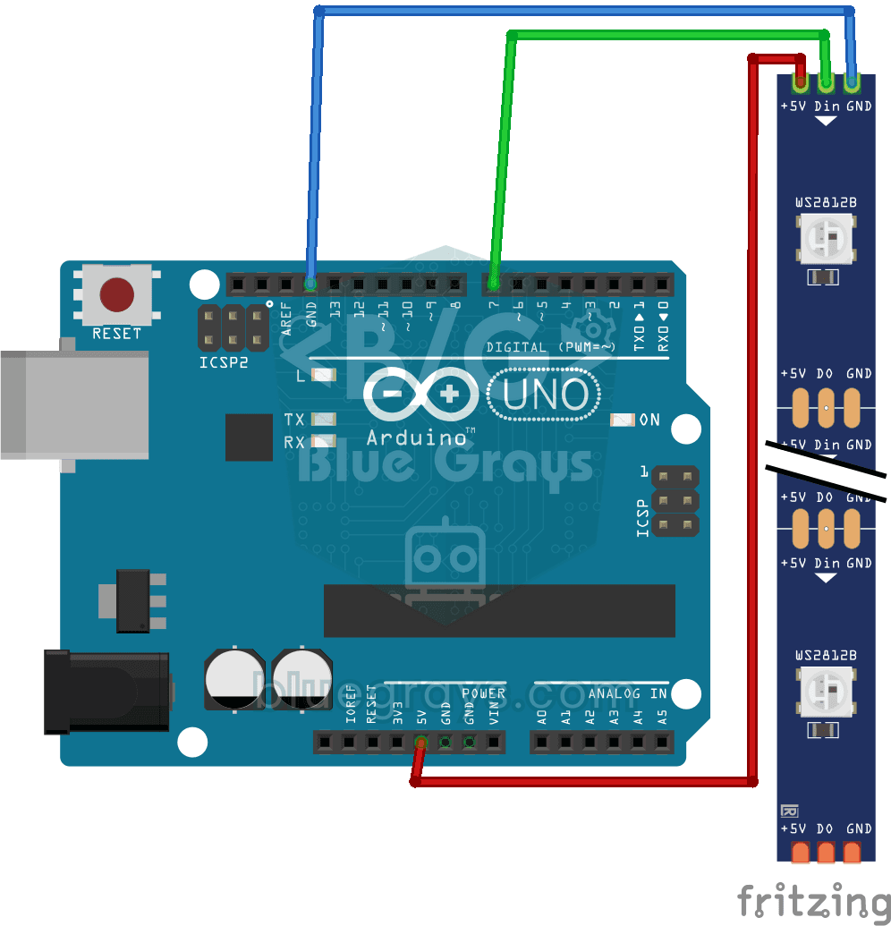
Meet a smart LED strip where you can colour every single light on its own. The Arduino first lights the first five LEDs red, a second later turns the other five blue, then switches them all off and…
Police Lights with WS2812B
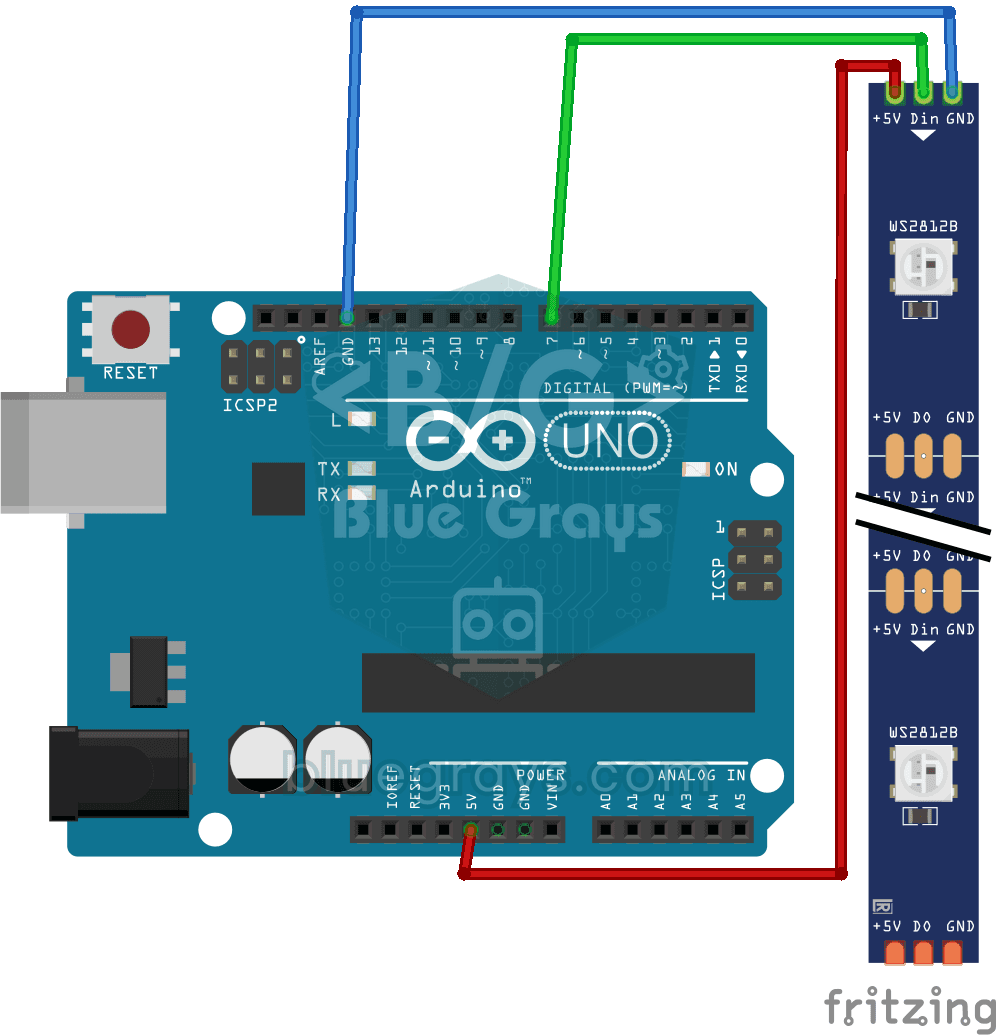
You bring the red and blue lights from the roof of a police car right onto your desk.
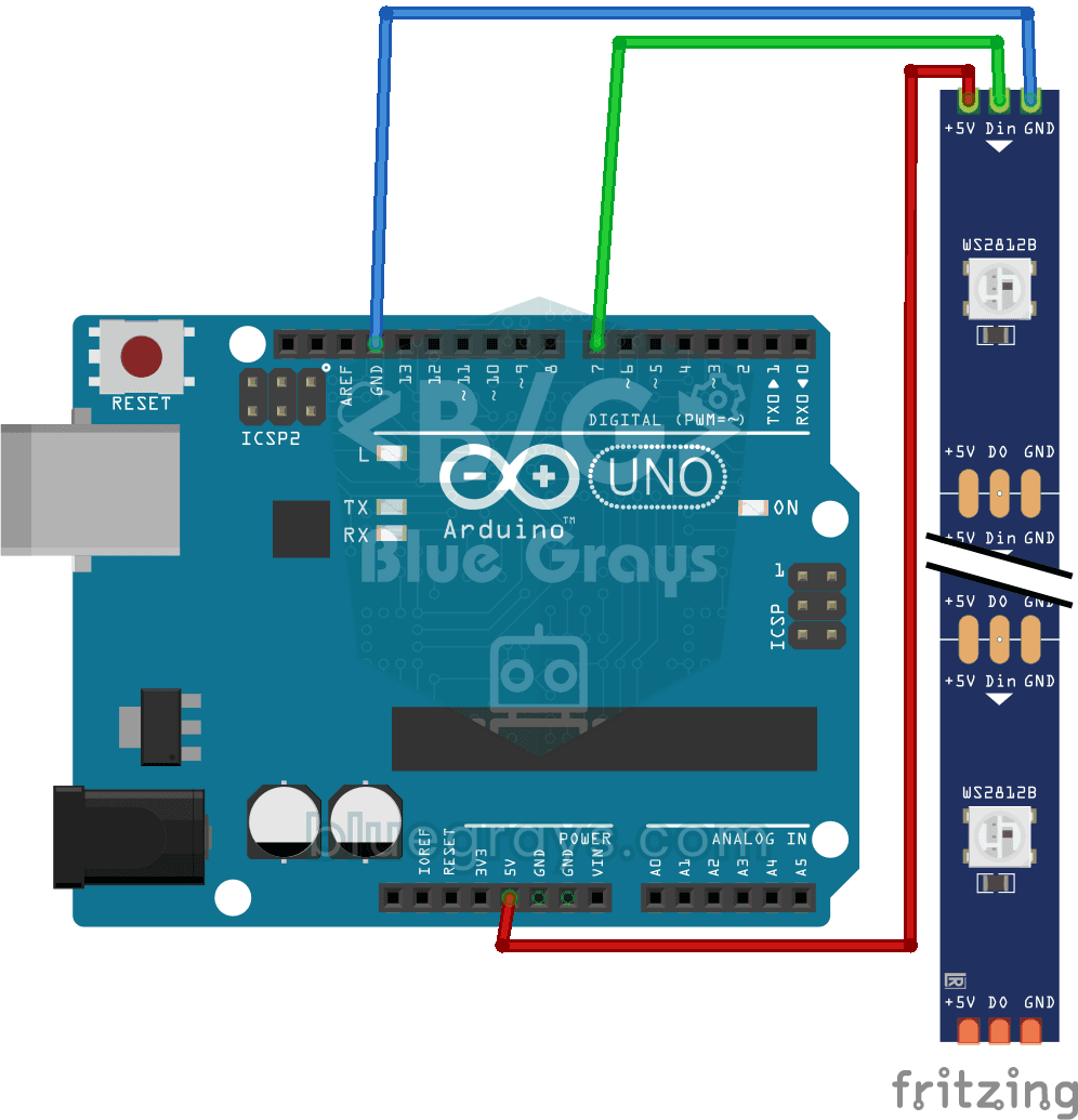
WS2812B LED Chaser
On a strip of ten LEDs, a green dot of light moves from start to finish one LED at a time, then jumps back to the beginning; it stays on each LED for a third of a second.
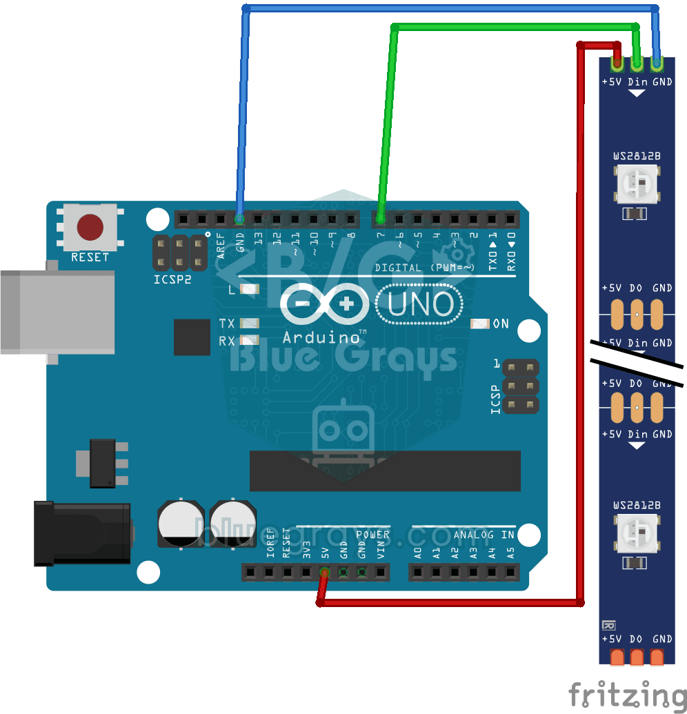
WS2812B LED Chaser (Fill Effect)
A light strip that fills up and empties like a glass of water. The Arduino lights ten color LEDs one by one in orange and keeps them on; once the strip is full, it switches them off one by one in the…
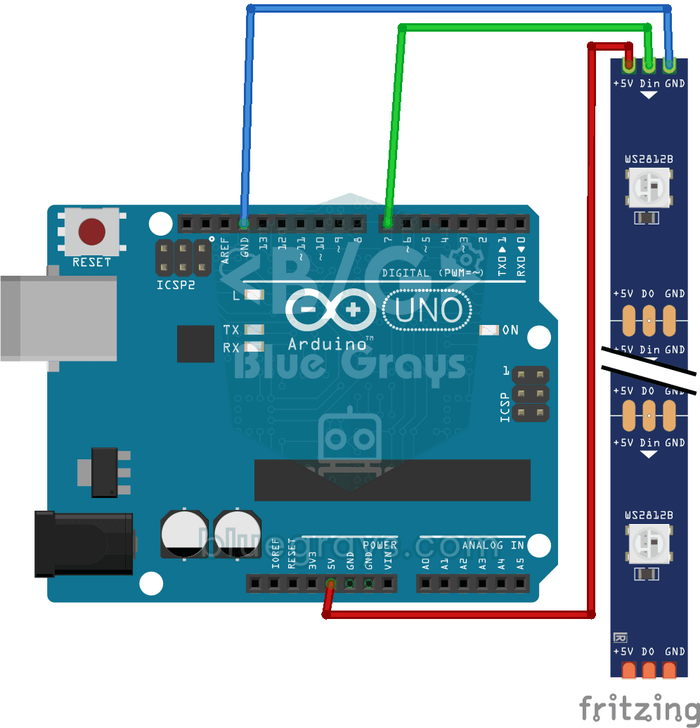
WS2812B Knight Rider Effect
A red dot of light slides from one end of a smart LED strip to the other, then comes back, sweeping back and forth without ever stopping.

WS2812B Animation 1
On a strip of 56 LEDs, all the colours of the rainbow line up side by side and flow without ever stopping, as if a river of light were gliding along the strip.

WS2812B Animation 2
Set up a light show in your room that changes colors all by itself. The Arduino keeps colors flowing along a 30-LED strip and switches to a new color set every few seconds: rainbow, purple and green…