
INMP441 ESP32 I2S Microphone: Read Audio, Measure dB, Plot
Connect the INMP441 I2S microphone to an ESP32: wiring table, 24-bit audio over I2S, dB level calculation, Serial Plotter waveform and Pico MicroPython code.
The INMP441 is a small MEMS microphone module that converts sound to digital inside the chip and sends 24-bit samples directly over the I2S bus. The INMP441 ESP32 pairing is the easiest way to get clean audio without an analog microphone, an amplifier or an ADC. You connect the module to the ESP32 with six wires, capture 16,000 samples per second with a few lines of I2S code, calculate the ambient sound level in decibels (dB) from those samples, and watch the sound waveform live in the Serial Plotter.
In this guide you'll see step by step how the INMP441 works, what the three I2S lines do, ready-made code that compiles on both the 2.x and 3.x ESP32 Arduino cores, the difference between dBFS and dB SPL, and the formula of a real sound level meter. At the end you'll also find MicroPython on the Raspberry Pi Pico, how it differs from the cheap analog KY-038 sound sensor, and the most common wiring mistakes.
What is the INMP441 and how does it work?
The INMP441 is an omnidirectional MEMS microphone made by TDK InvenSense. MEMS here means a tiny capacitor made of a microscopic membrane and a fixed plate etched into silicon: as sound waves vibrate the membrane, the capacitance changes. A classic electret microphone outputs this change as a weak analog voltage, and you have to amplify, filter and measure it with an ADC. Inside the INMP441, however, a preamplifier, an anti-aliasing filter, a 24-bit sigma-delta ADC and the I2S interface are all combined. So what comes out of the microphone is no longer a voltage but numbers that follow a clock signal. This way no analog noise is picked up on the wires, your board's ADC quality stops mattering, and any suitable 3.3 V microcontroller gets the same sound quality. The small hole on the module is the microphone's sound inlet; take care not to block it when mounting the board in an enclosure.
| Feature | Value |
|---|---|
| Type | MEMS, omnidirectional, digital-output microphone |
| Interface | I2S, 24-bit, MSB first, two's complement |
| Supply | 1.8–3.3 V |
| Current | About 1.4 mA |
| Sensitivity | −26 dBFS (1 kHz, 94 dB SPL) |
| Signal-to-noise ratio (SNR) | 61 dBA |
| Frequency response | 60 Hz – 15 kHz |
| Acoustic overload point (AOP) | 120 dB SPL |
| SCK frequency | About 0.5–3.2 MHz (sampling about 7.8–50 kHz) |
| Module pins | VDD, GND, SD, L/R, WS, SCK |
What is I2S? Digital audio over three lines
I2S (Inter-IC Sound) is a serial bus designed to carry audio samples between chips, and despite the similar name it has nothing to do with I2C. It has three lines: SCK (bit clock) says when each data bit should be read, WS (word select, also called LRCLK) says whether the left or right channel is being sent at that moment, and SD is the data itself. In this setup the ESP32 is the master: it generates both clocks, and the microphone follows the clock and puts data on the SD line. On the INMP441 each frame consists of 64 SCK pulses: 32 bits for the left channel and 32 bits for the right. That's why the sample rate is SCK / 64; for 16 kHz sampling the ESP32 generates a bit clock of about 1.024 MHz. The microphone writes its 24-bit measurement MSB first into the 32-bit slot of its own channel, and the remaining 8 bits are zero. That's why the code shifts the value right by 8 bits.
| INMP441 pin | Function |
|---|---|
| VDD | Supply, 1.8–3.3 V |
| GND | Ground |
| SCK | Bit clock input (comes from the board) |
| WS | Channel select clock input (comes from the board) |
| SD | Serial audio data output (from the microphone to the board) |
| L/R | Channel select: GND = left channel, VDD = right channel |
INMP441 wiring: ESP32 and Raspberry Pi Pico
| INMP441 pin | ESP32 | Raspberry Pi Pico |
|---|---|---|
| VDD | 3V3 | 3V3(OUT) (pin 36) |
| GND | GND | GND |
| SCK | GPIO 32 | GP16 |
| WS | GPIO 25 | GP17 |
| SD | GPIO 33 | GP18 |
| L/R | GND | GND |
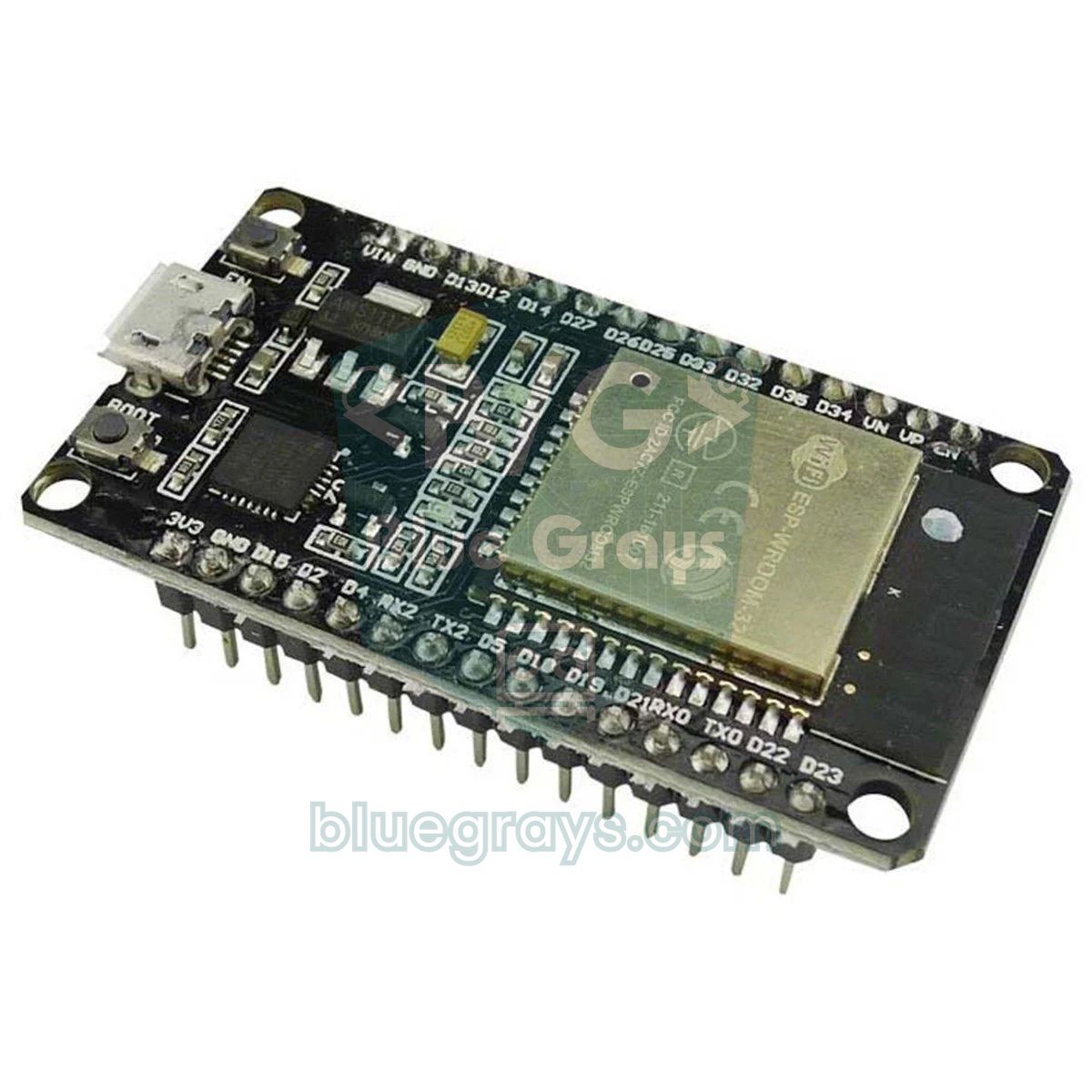
On the ESP32, I2S signals can be routed to any pin through the GPIO matrix; the numbers 32, 25 and 33 in the table aren't mandatory, just safe choices. Just stay away from the strapping pins that determine boot behaviour (GPIO 0, 2, 5, 12, 15) and GPIO 6–11, which are reserved for flash memory. GPIO 34–39 are input-only, so they suit the SD line but can't be used for SCK and WS. The Pico's rule is different: the MicroPython I2S driver uses PIO and the WS pin must be one higher than the SCK pin (such as GP16 and GP17). Keep the wires shorter than 10–15 cm; a clock signal in the megahertz range gets distorted on long jumper wires. You can check your board's pin layout in the pinout tool.
Step by step: your first audio reading with the ESP32
- Make sure the ESP32 board package is installed in the Arduino IDE and choose ESP32 Dev Module under Tools > Board. If you don't know how to install it, see What Is ESP32?.
- Plug the module into the breadboard; connect VDD to 3V3, GND to GND, and L/R to GND.
- Connect SCK to GPIO 32, WS to GPIO 25 and SD to GPIO 33, and keep the wires short.
- Upload the code below. No extra library is needed: ESP_I2S on the 3.x core and driver/i2s.h on the 2.x core are already included in the board package.
- Open the Serial Monitor at 115200 baud; in a quiet room you should see values of about 35–50 dB, and around 55–70 dB while talking.
- Open Tools > Serial Plotter to watch the dBFS and dB SPL curves live; clap next to the microphone and see the curve jump.
ESP32 code: measuring sound level (dB) with the INMP441
The code checks the ESP32 Arduino core version with ESP_ARDUINO_VERSION_MAJOR. On version 3.x it uses the new ESP_I2S library, and on 2.x it uses ESP-IDF's classic I2S driver. Both paths provide the same micBegin() and micRead() functions, so the calculation in loop() doesn't change. Each loop reads 512 samples, which is 32 ms of audio at 16 kHz, removes the DC offset, finds the RMS value and converts it to decibels.
1// INMP441 + ESP32: ses seviyesi (dB) olcer / sound level (dB) meter
2// ESP32 Arduino core 2.x ve 3.x / ESP32 Arduino core 2.x and 3.x
3#include <Arduino.h>
4#include <math.h>
5
6#define MIC_SCK 32   // INMP441 SCK
7#define MIC_WS  25   // INMP441 WS
8#define MIC_SD  33   // INMP441 SD
9
10const uint32_t SAMPLE_RATE = 16000;      // ornekleme hizi / sample rate
11const size_t   BLOCK       = 512;        // blok basina ornek / samples per block
12const double   FS_RMS      = 5931642.0;  // 8388608 / sqrt(2): tam olcek sinus RMS / full-scale sine RMS
13const double   DB_OFFSET   = 120.0;      // 94 dB SPL - (-26 dBFS)
14
15int32_t samples[BLOCK];
16
17#if ESP_ARDUINO_VERSION_MAJOR >= 3
18#include <ESP_I2S.h>
19I2SClass i2s;
20
21bool micBegin() {
22  i2s.setPins(MIC_SCK, MIC_WS, -1, MIC_SD);   // bclk, ws, dout (yok / none), din
23  return i2s.begin(I2S_MODE_STD, SAMPLE_RATE, I2S_DATA_BIT_WIDTH_32BIT,
24                   I2S_SLOT_MODE_MONO, I2S_STD_SLOT_LEFT);   // L/R = GND -> sol / left
25}
26
27size_t micRead(int32_t *buf, size_t count) {
28  size_t bytes = i2s.readBytes((char *)buf, count * sizeof(int32_t));
29  return bytes / sizeof(int32_t);
30}
31#else
32#include <driver/i2s.h>
33
34bool micBegin() {
35  i2s_config_t cfg = {};
36  cfg.mode = (i2s_mode_t)(I2S_MODE_MASTER | I2S_MODE_RX);   // ana cihaz, alici / master, receiver
37  cfg.sample_rate = SAMPLE_RATE;
38  cfg.bits_per_sample = I2S_BITS_PER_SAMPLE_32BIT;
39  cfg.channel_format = I2S_CHANNEL_FMT_ONLY_LEFT;           // L/R = GND -> sol / left
40  cfg.communication_format = I2S_COMM_FORMAT_STAND_I2S;
41  cfg.intr_alloc_flags = ESP_INTR_FLAG_LEVEL1;
42  cfg.dma_buf_count = 4;
43  cfg.dma_buf_len = 256;
44  cfg.use_apll = false;
45
46  i2s_pin_config_t pins = {};
47  pins.mck_io_num = I2S_PIN_NO_CHANGE;
48  pins.bck_io_num = MIC_SCK;
49  pins.ws_io_num = MIC_WS;
50  pins.data_out_num = I2S_PIN_NO_CHANGE;
51  pins.data_in_num = MIC_SD;
52
53  if (i2s_driver_install(I2S_NUM_0, &cfg, 0, NULL) != ESP_OK) return false;
54  return i2s_set_pin(I2S_NUM_0, &pins) == ESP_OK;
55}
56
57size_t micRead(int32_t *buf, size_t count) {
58  size_t bytes = 0;
59  i2s_read(I2S_NUM_0, buf, count * sizeof(int32_t), &bytes, portMAX_DELAY);
60  return bytes / sizeof(int32_t);
61}
62#endif
63
64void setup() {
65  Serial.begin(115200);
66  if (!micBegin()) {
67    Serial.println("I2S baslatilamadi / I2S init failed");
68    while (true) delay(1000);
69  }
70}
71
72void loop() {
73  size_t n = micRead(samples, BLOCK);
74  if (n == 0) return;
75
76  double sum = 0;
77  for (size_t i = 0; i < n; i++) {
78    samples[i] >>= 8;                 // 32 bit yuvadan 24 bit veri / 24-bit data from 32-bit slot
79    sum += samples[i];
80  }
81  double mean = sum / n;              // DC kaymasi / DC offset
82
83  double sq = 0;
84  for (size_t i = 0; i < n; i++) {
85    double v = (double)samples[i] - mean;
86    sq += v * v;
87  }
88  double rms = sqrt(sq / n);
89  if (rms < 1.0) rms = 1.0;           // log10(0) olmasin / avoid log10(0)
90
91  double dbfs = 20.0 * log10(rms / FS_RMS);
92  double spl = dbfs + DB_OFFSET;
93
94  Serial.print("dBFS:");
95  Serial.print(dbfs, 1);
96  Serial.print(" dB_SPL:");
97  Serial.println(spl, 1);
98}| Code part | What it does |
|---|---|
| SAMPLE_RATE = 16000 | Takes 16,000 samples per second; the SCK frequency becomes 16,000 × 64 = 1.024 MHz. It's enough for speech; for music you can choose 44,100 (SCK about 2.82 MHz). |
| 32-bit data width | The INMP441 expects 64 SCK pulses per WS frame; if you choose 16 bits the frame gets shorter and the data becomes meaningless. |
| MONO + LEFT / ONLY_LEFT | Only the left channel is read; since the L/R pin is tied to GND, the microphone uses the left slot. |
| samples[i] >>= 8 | Extracts the 24-bit measurement from the 32-bit slot; the value lies between −8,388,608 and +8,388,607. |
| Subtracting the mean | Removes the small DC offset in the signal; otherwise the RMS comes out larger than it should. |
| rms | The square root of the mean of the squared samples; it represents the average power of the sound. |
| dbfs + DB_OFFSET | Converts the result to dB SPL using the datasheet sensitivity of −26 dBFS @ 94 dB SPL. |
How is sound level calculated? dBFS and dB SPL
Because sound pressure varies over a very wide range, the logarithmic decibel scale is used: doubling the amplitude means about +6 dB, and ten times the amplitude means +20 dB. The numbers from the microphone are first converted to dBFS (decibels relative to full scale): dBFS = 20 × log10(RMS / full-scale RMS). Full scale is the RMS of a sine whose peak reaches the largest 24-bit value, 8,388,608, that is 8,388,608 / √2 ≈ 5,931,642. On this scale 0 dBFS is the microphone's clipping limit, and every quieter sound gets a negative value. To get to physical sound pressure, dB SPL, the datasheet sensitivity is used: the INMP441 outputs a 1 kHz sound at 94 dB SPL as −26 dBFS. From this comes the formula dB SPL = dBFS + 94 − (−26) = dBFS + 120. For example, if the RMS value is 5,932, then dBFS = 20 × log10(0.001) = −60 and the sound level is about 60 dB SPL, which is normal speech level.
| Sound source | Approx. dB SPL | dBFS on the INMP441 |
|---|---|---|
| Microphone's own noise floor | 33 | −87 |
| Quiet room | 40 | −80 |
| Normal speech (1 m) | 60 | −60 |
| Heavy traffic, vacuum cleaner | 70–80 | −50 to −40 |
| Hearing risk with prolonged exposure | 85 | −35 |
| Measurement reference (calibrator) | 94 | −26 |
| Drill, front of a concert stage | 100–110 | −20 to −10 |
| Microphone's upper limit (AOP) | 120 | 0 |
Plotting the waveform in Serial Plotter
The decibel value tells you how loud the sound is; to see the shape of the sound you need to plot the raw samples. In the same sketch, replace only the loop() function with the one below. There's an important limit here: a 115200-baud serial line carries about 11,500 characters per second, which isn't enough to print 16,000 samples per second. So the code prints a 512-sample block back to back; sound arriving while the block is being printed is missed, but every segment you see in the plotter is a continuous, real 32 ms slice.
1// dB taslaginda loop() yerine bunu kullan / Use this instead of loop() in the dB sketch
2void loop() {
3  size_t n = micRead(samples, BLOCK);
4  for (size_t i = 0; i < n; i++) {
5    int32_t v = samples[i] >> 8;     // 24 bit ham ornek / 24-bit raw sample
6    Serial.print("ses:");
7    Serial.println(v);
8  }
9}
When you whistle into the microphone you'll see a nearly smooth sine in the plotter. For a 1 kHz whistle one period lasts 1 ms and corresponds to 16 points at 16 kHz sampling; by counting the points in one period you can roughly estimate the frequency. Because speech is a mix of many frequencies, it draws an irregular, enveloped wave; a clap produces a short, very tall spike. Since the plotter scales its axis automatically, small noise fluctuations can look large in silence, which is normal. For details on using the Serial Monitor and Serial Plotter, see the Arduino Serial Monitor post.
INMP441 with the Raspberry Pi Pico (MicroPython)
The Raspberry Pi Pico has no dedicated I2S unit, but its programmable PIO blocks emulate I2S at hardware speed, and MicroPython's machine.I2S class does the work for you. You don't need to install any extra files; having a recent MicroPython version installed is enough. In the code you choose bits=32 and format=I2S.MONO, the samples read are again shifted right by 8 bits and converted to decibels with the same formula. Because Python loops are slower than C, keeping the block size at 512 samples is a good balance; missing a few milliseconds of sound while the calculation runs barely affects the result. If you program the Pico with the Arduino IDE, the I2S library in the arduino-pico core does the same job; there too the WS (LRCLK) pin must be one higher than the BCLK pin. If you're new to MicroPython, first take a look at What Is Raspberry Pi Pico?.
1from machine import Pin, I2S
2import array
3import math
4
5SCK_PIN = 16   # INMP441 SCK
6WS_PIN = 17    # INMP441 WS (SCK + 1 olmali / must be SCK + 1)
7SD_PIN = 18    # INMP441 SD
8
9FS_RMS = 5931642.0   # 8388608 / sqrt(2): tam olcek sinus RMS / full-scale sine RMS
10DB_OFFSET = 120.0    # 94 dB SPL - (-26 dBFS)
11LN10 = math.log(10)
12
13mic = I2S(0, sck=Pin(SCK_PIN), ws=Pin(WS_PIN), sd=Pin(SD_PIN),
14          mode=I2S.RX, bits=32, format=I2S.MONO,
15          rate=16000, ibuf=8192)
16
17samples = array.array('i', [0] * 512)   # 32 bit ornek dizisi / 32-bit sample array
18
19while True:
20    n = mic.readinto(samples) // 4      # okunan ornek sayisi / number of samples read
21    if n == 0:
22        continue
23    total = 0
24    for i in range(n):
25        samples[i] >>= 8                # 24 bit degeri ayikla / extract 24-bit value
26        total += samples[i]
27    mean = total / n                    # DC kaymasi / DC offset
28    sq = 0.0
29    for i in range(n):
30        d = samples[i] - mean
31        sq += d * d
32    rms = max(math.sqrt(sq / n), 1.0)
33    dbfs = 20 * math.log(rms / FS_RMS) / LN10
34    print("dBFS: {:.1f}  dB SPL: {:.1f}".format(dbfs, dbfs + DB_OFFSET))
INMP441 vs the KY-038 analog sound sensor
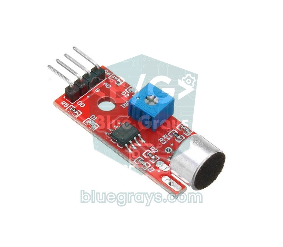
The KY-038 is a cheap module made of an electret microphone capsule, a trimpot for setting the threshold and an LM393 comparator. Its digital output (DO) changes state when the sound passes the threshold you set; its analog output (AO) gives the capsule's raw voltage and is read with the board's ADC. This design is enough for detecting claps or telling whether there's sound in the room. But because the module has no amplifier, the signal is very weak: the Arduino Uno's 10-bit ADC sees only a few steps of change in speech, and the ESP32's ADC is noisy. The INMP441, on the other hand, does the measurement inside the microphone at 24 bits; since there's no analog cable, amplifier or ADC in between, it records a range of about 87 dB, from the noise floor to the clipping limit, cleanly. In short, the KY-038 is a sound switch, while the INMP441 is a real microphone. You can find the limits of analog reading in detail in the ADC guide.
| Feature | INMP441 | KY-038 |
|---|---|---|
| Microphone type | MEMS, digital output | Electret capsule, analog |
| Output | I2S, 24-bit samples | AO analog voltage + DO threshold output |
| Supply | 1.8–3.3 V | 3.3–5 V |
| Compatible boards | ESP32, Pico and boards with I2S support | Any board, including the Uno |
| Sound quality | Good enough for recording and analysis (60 Hz – 15 kHz) | Rough level only |
| dB measurement | Possible with the formula | Not reliable |
| Typical use | Noise meter, audio recording, FFT, voice commands | Clap switch, sound present/absent alarm |
Project ideas with the INMP441
- Sound-reactive LEDs: turn the sound level into the number of lit LEDs on a WS2812B strip; for details see the sound-reactive LED and WS2812B NeoPixel posts.
- Classroom noise traffic light: build a warning lamp that glows green below 55 dB, yellow between 55–70 dB and red above.
- Live noise dashboard on the web: send the dB value to the browser over WebSocket and watch it as a graph on your phone; the basic structure is in ESP32 Web Server and WebSocket.
- Smart home noise sensor: send the measurements to Home Assistant over MQTT; the ESP32 MQTT and Home Assistant guide makes it easier.
- Baby cry or dog bark alert: if the sound exceeds the threshold for a certain time, send a message to your phone with a Telegram bot.
- Audio recorder: write the samples as a 16-bit WAV file to an SD card module and listen to it on your computer.
- Whistle control: find the dominant frequency with an FFT and trigger an LED or relay at a specific whistle tone.
Common mistakes and how to fix them
| Symptom | Likely cause | Fix |
|---|---|---|
| The dB SPL value stays fixed at around −15.5 | No data is coming from the SD line, all samples are 0 | Check the SD wire and that L/R is tied to GND; if that doesn't help, switch the channel to right (I2S_STD_SLOT_RIGHT on 3.x, I2S_CHANNEL_FMT_ONLY_RIGHT on 2.x) |
| The value doesn't rise with louder sound, it jumps randomly | SCK and WS are swapped or the wires are too long | Correct the pins according to the table and shorten the wires below 10–15 cm |
| "CONFLICT! The new i2s driver can't work along with the legacy i2s driver" error at startup | The old driver/i2s.h was used together with the new driver on the 3.x core | Use a single driver; the #if structure here picks the right one automatically |
| dB values differ from the sound level meter by 10–20 dB | Wrong bit shift, DC not removed or no calibration done | Set the shift to 8 bits, subtract the mean, calibrate with a steady tone |
| ValueError when creating I2S on the Pico | The WS pin isn't one higher than the SCK pin | Use consecutive pins such as SCK = GP16, WS = GP17 |
| The microphone gets hot or doesn't respond at all | VDD has been connected to 5 V | Move it to 3V3 immediately; the microphone may be damaged, so try a new one |
| The waveform looks choppy in Serial Plotter | The serial line can't carry 16,000 samples per second | This is normal; for a smoother view raise the baud rate to 921600 |
With a few wires and a short sketch, the INMP441 gives your ESP32 a real digital microphone; it's the foundation of many projects, from measuring sound level to sound-reactive lights. Whenever you want to process sound as numbers instead of settling for an analog sensor, it's the first choice. In the BlueGrays app you can follow step-by-step circuit diagrams and code for ESP32 projects with LEDs, buzzers, WS2812B strips and web servers, and easily add this microphone on top of them.
Frequently asked questions
Does the INMP441 work with an Arduino Uno?
No, not in practice. The Arduino Uno and Nano have no I2S hardware, they run on 5 V logic, and 2 KB of RAM isn't enough for an audio buffer. For the INMP441 you should use an ESP32, ESP32-S3, Raspberry Pi Pico or another 3.3 V board with I2S support.
What does the INMP441's L/R pin do?
The L/R pin selects which channel of the stereo frame the microphone uses: left if tied to GND, right if tied to 3.3 V. If you wire the SCK, WS and SD lines of two INMP441s together and set one to left and the other to right, you get stereo audio over a single I2S bus. Don't leave the pin floating; readings will be zero or unstable.
Can you record audio with the INMP441?
Yes. If you reduce the 24-bit samples to 16 bits and write them to an SD card with a WAV header, you get a recording you can play on your computer. 16 kHz sampling is enough for speech; one minute of 16-bit mono recording takes up about 1.9 MB.
How accurate is dB measurement with the INMP441?
A calculation using the datasheet sensitivity of −26 dBFS gives results within a few dB even without calibration; microphone sensitivity tolerance is ±1 dB. Because the calculation isn't A-weighted, it can read higher than a sound level meter in environments with a lot of low-frequency rumble. If you calibrate it against a known sound source you get very good results for room noise, but it doesn't replace an official measuring instrument.
Should I buy the INMP441 or the KY-038?
If you only want to detect a clap or loud sound and trigger something, the KY-038 is enough and works with any board. If you want to measure sound level in dB, record audio, do frequency analysis or build sound-reactive lights, the INMP441 gives much cleaner and more accurate results.
Why does the INMP441 always read 0 on the ESP32?
The most common causes are a floating L/R pin, a channel in the code that doesn't match the microphone's setting, and the SD wire plugged into the wrong pin. First tie L/R to GND, then try switching the channel in the code to right. Also make sure the bit width is 32 bits and the module is powered from 3V3.
Projects to build after reading this
See all projects
LED Blink with ESP32
Teaches basic GPIO output usage with ESP32. We achieve a blinking effect by turning an LED on and off from a digital pin. ESP32 version of the classic blink project on Arduino UNO; the basic blink commands in the Arduino environment are the same, but the ESP32's pin layout and 3.3 V GPIO levels differ from those of the Arduino UNO.
Using a Buzzer
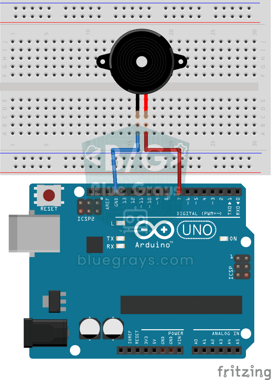
Ever wondered how a doorbell or an alarm makes its sound? The Arduino makes a small buzzer beep at short intervals: beep, pause, beep, pause. You see how sound is made with electricity and take the fi

ESP32 LED Fade with PWM
Smoothly changing the brightness of the LED from 0 to max, from max to 0. We control PWM with analogWrite() as in Arduino - the same syntax as ESP32 Arduino Core 3.0+ works without problems. Pin definition + pinMode + analogWrite is enough.

ESP32 Melody Playback with Buzzer
Playing a simple melody (Twinkle Twinkle Little Star) with a passive buzzer. We play notes with tone() and noTone() functions like in Arduino - ESP32 works with the same syntax as Arduino Core 3.0+. Passive buzzer must be used (active buzzer does not play melody).

ESP32 WS2812B NeoPixel Strip Control
WS2812B (NeoPixel) addressable LEDs are smart RGB LEDs that can be controlled in a daisy-chain configuration via a single data pin. In this project, we will control an 8-LED WS2812B strip using the Adafruit_NeoPixel library to create a smooth rainbow animation. While the ESP32’s 3.3V logic level works seamlessly with most WS2812B components, we’ll demonstrate a solution using a 470Ω series resistor and a 1000µF capacitor in case of instability. The animation is achieved by shifting the hue value

ESP32 Asynchronous Web Server (with IP Display on LCD)
In this project, we’re turning the ESP32 into an asynchronous web server that you can control from your phone or computer on the same Wi-Fi network. Thanks to the ESPAsyncWebServer library, the server can process multiple requests simultaneously (unlike the classic WebServer.h, which blocks on a single request). You’ll be able to open the ESP32’s IP address in a browser and click the ON/OFF buttons (the /on and /off routes) to turn the LED connected to GPIO 5 on and off.

ESP32 WebSocket Counter (2 Buttons + LCD + Real-Time Web)
In this project, two buttons wired to the ESP32 (GPIO 5 counts up, GPIO 4 counts down) change a counter. The value updates instantly both on a 16x2 I2C LCD and, through the WebSocket support of ESPAsyncWebServer, in every connected browser without reloading the page. Instead of HTTP polling a single persistent connection is used, and the ESP32 sends the new value to everyone with ws.textAll().

ESP32 HTTPClient + Weather API (with SSD1306 OLED Display)
In this project, we use the ESP32 to make a REST API call to a weather API (wttr.in) over the internet using HTTPClient.h. Unlike the previous I2C LCD version, we’re using an SSD1306 OLED (128×64) display here—which allows for large fonts, vector icons, and rich visual presentation on a single screen. Seven different vector icons for weather conditions (sunny, partly cloudy, cloudy, rainy, snowy, stormy, foggy) are drawn at runtime (no bitmap files required). The temperature is displayed in th