
Arduino Compass Module: QMC5883L and HMC5883L (GY-271) Guide
Is your GY-271 a QMC5883L or HMC5883L? I2C addresses (0x0D, 0x1E), heading with atan2, declination, calibration and an OLED compass, with Uno, ESP32 and Pico code.

An Arduino compass module is a small magnetic field sensor that tells your board where north is. The most common model, the GY-271, measures the Earth's magnetic field on three axes. From that you can calculate a heading (0–360 degrees) to steer your robot car in a set direction, show a digital compass on an OLED display, or add direction data to your GPS project. The module connects with just four wires over I2C and works the same way with Arduino Uno, ESP32 and Raspberry Pi Pico.
But this module has a surprise: most boards sold as GY-271 no longer carry Honeywell's HMC5883L chip but QST's QMC5883L. The two chips look almost identical from the outside, yet their I2C addresses and registers differ, which is why many ready-made sketches report "sensor not found". In this post you'll learn to find out which chip your board has, calculate the heading correctly, add magnetic declination and bring the error down to a few degrees with calibration.
What is a digital compass module and how does it work?
At the heart of the module is a magnetometer, a sensor that measures magnetic fields. The Earth's field is quite weak: in Turkey its total strength is about 45–50 microtesla (0.45–0.5 gauss), and the horizontal component parallel to the ground is around 25 µT (1 gauss = 100 µT). The chip uses magnetoresistive sensors to measure the field's X, Y and Z components and gives each as a signed integer. While the module is level, X and Y are enough to find the heading; you get the angle from them with the atan2 function. The Z axis is useful for advanced things like tilt compensation and metal detection.
| Feature | QMC5883L | HMC5883L |
|---|---|---|
| Manufacturer | QST | Honeywell (discontinued) |
| I2C address | 0x0D | 0x1E |
| Measurement range | ±2 G or ±8 G | ±0.88 G to ±8.1 G (8 steps) |
| Resolution | 16-bit (12000 LSB/G at ±2 G, 3000 LSB/G at ±8 G) | 12-bit (1090 LSB/G at ±1.3 G) |
| Data rate | 10, 50, 100, 200 Hz | 0.75–75 Hz (continuous mode) |
| Chip supply | 2.16–3.6 V | 2.16–3.6 V |
| GY-271 board supply | 3–5 V (regulator on the board) | 3–5 V (regulator on the board) |
| Temperature reading | Yes (relative value) | No |
QMC5883L or HMC5883L? How to tell the two chips apart
For many years the HMC5883L was the standard compass chip in hobby electronics. When Honeywell stopped production, QST's QMC5883L filled the market. Because sellers often don't change the product name, finding a QMC5883L on a board you bought as "HMC5883L" is completely normal. The surest way to tell is an I2C scan: if address 0x0D shows up on the bus, it's a QMC5883L; if 0x1E shows up, it's an HMC5883L. Reading the marking on the chip with a magnifier also helps. Lately some boards carry a QMC5883P at address 0x2C; its register map is different, so the code in this post won't work with it directly.
| Method | QMC5883L | HMC5883L |
|---|---|---|
| I2C address | 0x0D | 0x1E |
| Marking on the chip | DA 5883 | L883 |
| ID register | Register 0x0D returns 0xFF | Registers 0x0A–0x0C return 'H', '4', '3' |
| Data registers | 0x00–0x05 (X, Y, Z in order) | 0x03–0x08 (X, Z, Y in order) |
| Byte order | Low byte first (LSB) | High byte first (MSB) |
| Mode at power-up | Standby, doesn't measure | Single measurement mode |
| Common library | QMC5883LCompass | Adafruit HMC5883 Unified |
GY-271 wiring: Uno, ESP32 and Pico
| GY-271 pin | Arduino Uno | ESP32 | Raspberry Pi Pico |
|---|---|---|---|
| VCC | 5V (or 3.3V) | 3V3 | 3V3 (pin 36) |
| GND | GND | GND | GND |
| SCL | A5 | GPIO 22 | GP5 (pin 7) |
| SDA | A4 | GPIO 21 | GP4 (pin 6) |
| DRDY | Not connected | Not connected | Not connected |
The GY-271 board has a 3.3 V regulator and pull-up resistors for the I2C lines, so it's safe to power the module from the 5V pin on the Uno. On the ESP32 and Pico, power the board from the 3V3 pin so that SDA and SCL stay at 3.3 V. The DRDY (data ready) pin signals every new measurement; you can leave it open if you won't read by interrupt. The compass can share the same bus with other I2C devices such as an OLED display (0x3C) or an MPU-6050 (0x68), because their addresses don't clash. For details on addresses and pull-ups, see What is I2C.
Step by step: your first heading reading (Arduino Uno)
- Plug the module into the breadboard, keeping it at least 15–20 cm away from motors, speakers, magnets and large steel parts if possible.
- Connect the VCC, GND, SCL and SDA wires as in the table and leave the DRDY pin open.
- Upload the code below; no extra library is needed, only Arduino's own Wire library.
- Open the Serial Monitor at 9600 baud; the first line shows which chip the code found.
- Lay the module flat on the desk and slowly rotate it; watch the X and Y values swing between positive and negative and the angle move from 0 to 360.
- If your phone compass is set to show true north, point the X arrow on the module to that north; the angle should approach 0. A 10–30 degree error before calibration is normal.
1#include <Wire.h>
2#include <math.h>
3
4const uint8_t QMC_ADDR = 0x0D;   // QMC5883L adresi / QMC5883L address
5const uint8_t HMC_ADDR = 0x1E;   // HMC5883L adresi / HMC5883L address
6const float DECLINATION = 6.0;   // manyetik sapma, doğu + / magnetic declination, east +
7
8uint8_t chipAddr = 0;
9
10bool devicePresent(uint8_t addr) {
11  Wire.beginTransmission(addr);
12  return Wire.endTransmission() == 0;   // 0 = cihaz cevap verdi / 0 = device acknowledged
13}
14
15void writeReg(uint8_t addr, uint8_t reg, uint8_t val) {
16  Wire.beginTransmission(addr);
17  Wire.write(reg);
18  Wire.write(val);
19  Wire.endTransmission();
20}
21
22bool readAxes(int16_t &x, int16_t &y, int16_t &z) {
23  uint8_t startReg = (chipAddr == QMC_ADDR) ? 0x00 : 0x03;
24  Wire.beginTransmission(chipAddr);
25  Wire.write(startReg);
26  if (Wire.endTransmission() != 0) return false;
27  if (Wire.requestFrom(chipAddr, (uint8_t)6) != 6) return false;
28  uint8_t b[6];
29  for (uint8_t i = 0; i < 6; i++) b[i] = Wire.read();
30  if (chipAddr == QMC_ADDR) {          // X, Y, Z; önce düşük bayt / LSB first
31    x = (int16_t)((uint16_t)b[1] << 8 | b[0]);
32    y = (int16_t)((uint16_t)b[3] << 8 | b[2]);
33    z = (int16_t)((uint16_t)b[5] << 8 | b[4]);
34  } else {                             // X, Z, Y; önce yüksek bayt / MSB first
35    x = (int16_t)((uint16_t)b[0] << 8 | b[1]);
36    z = (int16_t)((uint16_t)b[2] << 8 | b[3]);
37    y = (int16_t)((uint16_t)b[4] << 8 | b[5]);
38  }
39  return true;
40}
41
42const char* directionName(float h) {
43  static const char* const names[] = {"K", "KD", "D", "GD", "G", "GB", "B", "KB"};
44  return names[(int)((h + 22.5) / 45.0) % 8];   // 45 derecelik dilimler / 45 degree sectors
45}
46
47void setup() {
48  Serial.begin(9600);
49  Wire.begin();
50  if (devicePresent(QMC_ADDR)) {
51    chipAddr = QMC_ADDR;
52    writeReg(QMC_ADDR, 0x0B, 0x01);   // SET/RESET periyodu / SET/RESET period
53    writeReg(QMC_ADDR, 0x09, 0x1D);   // sürekli, 200 Hz, ±8 G, OSR 512 / continuous, 200 Hz, ±8 G, OSR 512
54    Serial.println(F("QMC5883L bulundu (0x0D)"));
55  } else if (devicePresent(HMC_ADDR)) {
56    chipAddr = HMC_ADDR;
57    writeReg(HMC_ADDR, 0x00, 0x70);   // 8 örnek ortalama, 15 Hz / 8-sample average, 15 Hz
58    writeReg(HMC_ADDR, 0x01, 0x20);   // ±1,3 Ga kazanç / ±1.3 Ga gain
59    writeReg(HMC_ADDR, 0x02, 0x00);   // sürekli ölçüm / continuous measurement
60    Serial.println(F("HMC5883L bulundu (0x1E)"));
61  } else {
62    Serial.println(F("Pusula bulunamadi / Compass not found"));
63    while (true) {}
64  }
65}
66
67void loop() {
68  int16_t x, y, z;
69  if (readAxes(x, y, z)) {
70    float heading = atan2((float)y, (float)x) * 180.0 / PI;   // radyandan dereceye / radians to degrees
71    heading += DECLINATION;
72    if (heading < 0) heading += 360.0;
73    if (heading >= 360.0) heading -= 360.0;
74    Serial.print(F("X: ")); Serial.print(x);
75    Serial.print(F("  Y: ")); Serial.print(y);
76    Serial.print(F("  Z: ")); Serial.print(z);
77    Serial.print(F("  Yon: ")); Serial.print(heading, 1);
78    Serial.print(F(" derece "));
79    Serial.println(directionName(heading));
80  }
81  delay(250);
82}| Code / register | Value | Meaning |
|---|---|---|
| QMC 0x0B | 0x01 | SET/RESET period; the value recommended by the datasheet |
| QMC 0x09 | 0x1D | OSR 512, ±8 G range, 200 Hz, continuous measurement (0x0D for ±2 G) |
| HMC 0x00 | 0x70 | Average of 8 measurements, 15 Hz data rate |
| HMC 0x01 | 0x20 | ±1.3 Ga range, 1090 LSB/Ga sensitivity |
| HMC 0x02 | 0x00 | Continuous measurement mode |
| Wire.endTransmission() == 0 | - | If the address answered, the device is on the bus |
| atan2(y, x) × 180 / π | - | Angle from −180 to +180 degrees from the raw axes |
How is the heading calculated?
While the module is level, the Earth's horizontal magnetic field is shared between the X and Y axes. When you point the X arrow north, all of the field falls on X and Y approaches zero; as you rotate the module, the share shifts to Y. The heading is found with θ = atan2(Y, X). We use atan2 instead of a simple atan(Y/X) because atan2 looks at the signs of both values to tell all four quadrants apart and doesn't divide by zero when X is zero. The result comes out in radians between −180 and +180 degrees; you multiply by 180/π to convert to degrees and add 360 if it's negative. Each of the eight main directions covers a 45-degree sector: 337.5 to 22.5 degrees is North (N), 22.5 to 67.5 is Northeast (NE), and so on; the (angle + 22.5) / 45 operation in the code picks the right sector. If the angle decreases when you rotate the module clockwise, your board's axis layout is different; flip the sign of Y and use atan2(-y, x) to fix it.
What is magnetic declination?
A compass needle points to magnetic north, not geographic (true) north. The angle between the two is called magnetic declination, and it changes with your location and the year. In Turkey the declination is easterly and today is about +5 degrees in the western provinces and about +7 degrees in the east; 6 degrees is a good starting point for Istanbul and Ankara. The correction formula is simple: true heading = magnetic heading + declination, with east written as positive and west as negative. Just look up the current value for your location in NOAA's or a similar agency's magnetic model calculator and write it into the DECLINATION constant in the code. If you find the value in degrees and minutes, convert it to a decimal: 5° 48' = 5 + 48/60 = 5.8 degrees. Declination drifts a few arcminutes per year, so it's good to check it every few years.
Compass calibration: hard iron and soft iron
An uncalibrated compass can be off by 20–40 degrees, especially on the first try. There are two causes. With the hard iron effect, permanent magnets near the module, magnetised screws or parts on the board add a constant value to every reading; if you plot the X–Y values while rotating the module, you'll see the centre of the circle shifted away from zero. With the soft iron effect, nearby materials such as iron and nickel bend the field and turn the circle into an ellipse. The fix is simple: hold the module flat in the final position it will have in your project, rotate it slowly two or three turns and record the minimum and maximum of each axis. Offset = (max + min) / 2 gives the hard iron correction, and scale = average radius / axis radius gives a simple soft iron correction. The code below is for the QMC5883L found on most boards; if you use an HMC5883L, just swap the read function for the HMC part in the first sketch.
1#include <Wire.h>
2
3const uint8_t QMC_ADDR = 0x0D;
4int16_t minX = 32767, maxX = -32768;
5int16_t minY = 32767, maxY = -32768;
6unsigned long samples = 0;
7unsigned long lastPrint = 0;
8
9void qmcInit() {
10  Wire.beginTransmission(QMC_ADDR);
11  Wire.write(0x0B); Wire.write(0x01);    // SET/RESET periyodu / SET/RESET period
12  Wire.endTransmission();
13  Wire.beginTransmission(QMC_ADDR);
14  Wire.write(0x09); Wire.write(0x1D);    // sürekli, 200 Hz, ±8 G / continuous, 200 Hz, ±8 G
15  Wire.endTransmission();
16}
17
18bool qmcRead(int16_t &x, int16_t &y, int16_t &z) {
19  Wire.beginTransmission(QMC_ADDR);
20  Wire.write(0x00);
21  if (Wire.endTransmission() != 0) return false;
22  if (Wire.requestFrom(QMC_ADDR, (uint8_t)6) != 6) return false;
23  uint8_t b[6];
24  for (uint8_t i = 0; i < 6; i++) b[i] = Wire.read();
25  x = (int16_t)((uint16_t)b[1] << 8 | b[0]);
26  y = (int16_t)((uint16_t)b[3] << 8 | b[2]);
27  z = (int16_t)((uint16_t)b[5] << 8 | b[4]);
28  return true;
29}
30
31void setup() {
32  Serial.begin(9600);
33  Wire.begin();
34  qmcInit();
35  Serial.println(F("Modulu duz tutup yavasca 2-3 tur cevir / Rotate it flat, slowly, 2-3 turns"));
36}
37
38void loop() {
39  int16_t x, y, z;
40  if (qmcRead(x, y, z)) {
41    if (x < minX) minX = x;
42    if (x > maxX) maxX = x;
43    if (y < minY) minY = y;
44    if (y > maxY) maxY = y;
45    samples++;
46  }
47  if (samples > 50 && millis() - lastPrint > 1000) {
48    lastPrint = millis();
49    float offX = ((long)maxX + minX) / 2.0;   // hard iron ofseti / hard iron offset
50    float offY = ((long)maxY + minY) / 2.0;
51    float dX = ((long)maxX - minX) / 2.0;     // eksen yarıçapı / axis radius
52    float dY = ((long)maxY - minY) / 2.0;
53    float avg = (dX + dY) / 2.0;              // ortalama yarıçap / average radius
54    Serial.print(F("OFF_X=")); Serial.print(offX, 1);
55    Serial.print(F("  OFF_Y=")); Serial.print(offY, 1);
56    if (dX > 0 && dY > 0) {
57      Serial.print(F("  SCALE_X=")); Serial.print(avg / dX, 3);
58      Serial.print(F("  SCALE_Y=")); Serial.print(avg / dY, 3);
59    }
60    Serial.println();
61  }
62  delay(20);
63}
The code prints the OFF and SCALE values every second; keep rotating until the numbers stop changing. For example, if you measured a minimum of −680 and a maximum of 920 for X, the offset is (920 + (−680)) / 2 = 120 and the radius is 800. If Y has a minimum of −1010 and a maximum of 550, the offset is −230 and the radius is 780. Since the average radius is 790, the scales come out as 790 / 800 ≈ 0.988 and 790 / 780 ≈ 1.013. In the main code you correct every raw reading as x = (raw_x − OFF_X) × SCALE_X; in the ESP32 example below these values are already filled in. Because 1 gauss equals 3000 counts in the ±8 G range, a radius of 800 means a horizontal field of about 0.27 G, which matches what's expected for Turkey. If you move the module somewhere else or add a new metal part nearby, repeat the calibration.
A compass on an OLED display with the ESP32
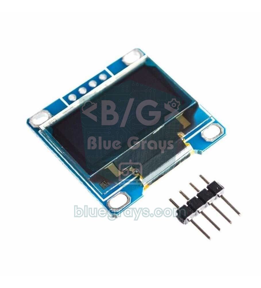
The same Wire code works on the ESP32; the I2C pins are GPIO 21 (SDA) and GPIO 22 (SCL), and the compass and the 0.96-inch OLED display connect to the same bus. The code applies the calibration values, smooths X and Y with a simple low-pass filter, and shows a rotating compass needle on the left of the screen and the degrees and direction letter on the right. We apply the filter to the axes rather than the angle so that averaging angles across the 359-to-0 degree wrap doesn't wrongly come out around 180. The short line at the top of the screen marks the front of the device and the needle points north; as you turn the device, the needle turns the opposite way, just like a real compass. For installing the display libraries, see OLED display (SSD1306).
1#include <Wire.h>
2#include <Adafruit_GFX.h>
3#include <Adafruit_SSD1306.h>
4#include <math.h>
5
6Adafruit_SSD1306 display(128, 64, &Wire, -1);
7
8const uint8_t QMC_ADDR = 0x0D;
9const float DECLINATION = 6.0;                  // şehrine göre değiştir / change for your city
10const float OFF_X = 120.0, OFF_Y = -230.0;      // kalibrasyon kodundan / from calibration sketch
11const float SCALE_X = 0.988, SCALE_Y = 1.013;
12
13float fx = 0, fy = 0;                           // filtrelenmiş eksenler / filtered axes
14bool firstRead = true;
15
16void qmcInit() {
17  Wire.beginTransmission(QMC_ADDR);
18  Wire.write(0x0B); Wire.write(0x01);           // SET/RESET periyodu / SET/RESET period
19  Wire.endTransmission();
20  Wire.beginTransmission(QMC_ADDR);
21  Wire.write(0x09); Wire.write(0x1D);           // sürekli, 200 Hz, ±8 G / continuous, 200 Hz, ±8 G
22  Wire.endTransmission();
23}
24
25bool qmcRead(int16_t &x, int16_t &y, int16_t &z) {
26  Wire.beginTransmission(QMC_ADDR);
27  Wire.write(0x00);
28  if (Wire.endTransmission() != 0) return false;
29  if (Wire.requestFrom(QMC_ADDR, (uint8_t)6) != 6) return false;
30  uint8_t b[6];
31  for (uint8_t i = 0; i < 6; i++) b[i] = Wire.read();
32  x = (int16_t)((uint16_t)b[1] << 8 | b[0]);
33  y = (int16_t)((uint16_t)b[3] << 8 | b[2]);
34  z = (int16_t)((uint16_t)b[5] << 8 | b[4]);
35  return true;
36}
37
38const char* directionName(float h) {
39  static const char* const names[] = {"K", "KD", "D", "GD", "G", "GB", "B", "KB"};
40  return names[(int)((h + 22.5f) / 45.0f) % 8];
41}
42
43void setup() {
44  Serial.begin(115200);
45  Wire.begin(21, 22);                           // SDA = GPIO 21, SCL = GPIO 22
46  qmcInit();
47  if (!display.begin(SSD1306_SWITCHCAPVCC, 0x3C)) {
48    Serial.println(F("OLED bulunamadi / OLED not found"));
49    for (;;) delay(1000);
50  }
51  display.setTextColor(SSD1306_WHITE);
52}
53
54void loop() {
55  int16_t rx, ry, rz;
56  if (!qmcRead(rx, ry, rz)) { delay(100); return; }
57
58  float x = (rx - OFF_X) * SCALE_X;             // kalibrasyonu uygula / apply calibration
59  float y = (ry - OFF_Y) * SCALE_Y;
60  if (firstRead) { fx = x; fy = y; firstRead = false; }
61  fx = 0.8f * fx + 0.2f * x;                    // basit alçak geçiren filtre / simple low-pass filter
62  fy = 0.8f * fy + 0.2f * y;
63
64  float heading = atan2f(fy, fx) * 180.0f / PI + DECLINATION;
65  if (heading < 0) heading += 360.0f;
66  if (heading >= 360.0f) heading -= 360.0f;
67
68  display.clearDisplay();
69  const int cx = 32, cy = 32, r = 30;
70  display.drawCircle(cx, cy, r, SSD1306_WHITE);
71  display.drawFastVLine(cx, 0, 4, SSD1306_WHITE);   // cihazın ön yönü / device forward mark
72
73  float a = heading * PI / 180.0f;
74  int nx = cx - (int)(24 * sinf(a));            // kuzeyi gösteren uç / tip pointing north
75  int ny = cy - (int)(24 * cosf(a));
76  int sx = cx + (int)(12 * sinf(a));            // güney ucu / south tail
77  int sy = cy + (int)(12 * cosf(a));
78  display.drawLine(sx, sy, nx, ny, SSD1306_WHITE);
79  display.fillCircle(nx, ny, 3, SSD1306_WHITE);
80  display.fillCircle(cx, cy, 2, SSD1306_WHITE);
81
82  display.setTextSize(2);
83  display.setCursor(72, 10);
84  display.print((int)(heading + 0.5f) % 360);
85  display.drawCircle(display.getCursorX() + 3, 12, 2, SSD1306_WHITE);   // derece işareti / degree sign
86  display.setCursor(72, 38);
87  display.print(directionName(heading));
88  display.display();
89  delay(100);
90}
A MicroPython compass with the Raspberry Pi Pico
On the Pico, MicroPython's machine.I2C class is enough; no separate driver file is needed. The code first lists the addresses on the bus with i2c.scan(), writes the settings for whichever chip it finds and reads six bytes at once with readfrom_mem. Since bytes arrive unsigned in MicroPython, you need to subtract 65536 from values above 32767 to turn them into negative numbers. For calibration, just put the OFF and SCALE values you found on the Arduino into the constants in the code. If you're new to MicroPython, MicroPython basics and What is the Raspberry Pi Pico are good places to start.
1from machine import Pin, I2C
2import math
3import time
4
5i2c = I2C(0, sda=Pin(4), scl=Pin(5), freq=400000)
6QMC = 0x0D
7HMC = 0x1E
8DECLINATION = 6.0                  # manyetik sapma, doğu + / magnetic declination, east +
9OFF_X, OFF_Y = 0.0, 0.0            # kalibrasyon ofsetleri / calibration offsets
10SCALE_X, SCALE_Y = 1.0, 1.0        # kalibrasyon ölçekleri / calibration scales
11
12found = i2c.scan()
13print("I2C:", [hex(a) for a in found])
14
15if QMC in found:
16    addr = QMC
17    i2c.writeto_mem(QMC, 0x0B, bytes([0x01]))   # SET/RESET periyodu / SET/RESET period
18    i2c.writeto_mem(QMC, 0x09, bytes([0x1D]))   # sürekli, 200 Hz, ±8 G / continuous, 200 Hz, ±8 G
19elif HMC in found:
20    addr = HMC
21    i2c.writeto_mem(HMC, 0x00, bytes([0x70]))   # 8 ortalama, 15 Hz / 8 samples, 15 Hz
22    i2c.writeto_mem(HMC, 0x01, bytes([0x20]))   # ±1,3 Ga kazanç / ±1.3 Ga gain
23    i2c.writeto_mem(HMC, 0x02, bytes([0x00]))   # sürekli mod / continuous mode
24else:
25    raise OSError("Pusula bulunamadi / Compass not found")
26
27def to_int16(v):
28    return v - 65536 if v > 32767 else v
29
30def read_xyz():
31    if addr == QMC:
32        b = i2c.readfrom_mem(QMC, 0x00, 6)      # X, Y, Z; önce düşük bayt / LSB first
33        x = to_int16(b[1] << 8 | b[0])
34        y = to_int16(b[3] << 8 | b[2])
35        z = to_int16(b[5] << 8 | b[4])
36    else:
37        b = i2c.readfrom_mem(HMC, 0x03, 6)      # X, Z, Y; önce yüksek bayt / MSB first
38        x = to_int16(b[0] << 8 | b[1])
39        z = to_int16(b[2] << 8 | b[3])
40        y = to_int16(b[4] << 8 | b[5])
41    return x, y, z
42
43NAMES = ("K", "KD", "D", "GD", "G", "GB", "B", "KB")
44
45while True:
46    x, y, z = read_xyz()
47    x = (x - OFF_X) * SCALE_X
48    y = (y - OFF_Y) * SCALE_Y
49    heading = (math.degrees(math.atan2(y, x)) + DECLINATION) % 360
50    name = NAMES[int((heading + 22.5) // 45) % 8]
51    print("Yon: {:.1f} derece {}".format(heading, name))
52    time.sleep(0.2)
Tilt compensation: why must the module stay level?
A heading calculated from only the X and Y axes is correct only while the module is parallel to the ground. At mid-latitudes like Turkey, the magnetic field enters the ground at a dip of about 55–60 degrees, so the vertical (Z) component is clearly larger than the horizontal one. When the module is tilted by 10 degrees, part of the Z component leaks into X or Y and the heading can drift by an error of up to 15 degrees. For handheld or swaying devices, the fix is tilt compensation: you find the roll and pitch angles with an MPU-6050 accelerometer and rotate the magnetometer values onto the horizontal plane. For simple projects like a robot car or a fixed box, mounting the module flat and firmly on the body is often enough.
Project ideas with the compass module
- Heading-holding robot car: teach your robot car to turn to a set angle and drive straight; mount the module on a plastic pole away from the motors.
- GPS navigation to a target: calculate the bearing to the target with a NEO-6M GPS and show the difference from the compass as an arrow on the display.
- Servo-needle compass: turn the arm of a servo motor so it always points north, however you rotate the box.
- Qibla finder: write your city's qibla angle into the code and rotate the arrow on the OLED according to that angle instead of north.
- Solar panel orientation: use the compass to check that the panel faces the right direction in a solar tracking system.
- Direction-telling cane: add a mode to the smart cane project that gives a short vibration when the user faces north.
- Magnet and metal detector: calculate the total field strength from the three axes and sound a buzzer when the value suddenly rises.
Common mistakes and how to fix them
| Symptom | Likely cause | Fix |
|---|---|---|
| "No HMC5883 detected" error | The board has a QMC5883L | Use code for address 0x0D or the QMC5883LCompass library |
| No addresses at all in the I2C scan | SDA and SCL swapped, no power or a broken wire | Check the wires and measure the voltage on the VCC pin |
| X, Y, Z always 0 or never change | The QMC5883L is in standby at power-up | Write the continuous mode setting (0x1D) to register 0x09 |
| The angle doesn't sweep the full 360 degrees | The hard iron offset is too large | Calibrate and subtract the OFF values |
| The angle decreases when rotating clockwise | The board's axis layout is different | Use atan2(-y, x) |
| The heading drifts when the motor runs | Motor magnets and high-current wires | Move the module 15–20 cm away, onto a pole |
| The heading is off when tilted | No tilt compensation | Mount the module flat or compensate with an MPU-6050 |
Once you've identified the right chip and calibrated it, the GY-271 compass module is one of the cheapest ways to give your projects a sense of direction. To show the heading you can use an I2C LCD or OLED display, and to turn it into motion you can use a servo, a stepper motor or a robot car. In the BlueGrays app you'll find these display, motor and robot projects with step-by-step circuit diagrams and code, and you can easily add the compass module to them.
Frequently asked questions
Does my GY-271 have a QMC5883L or an HMC5883L?
The easiest way is an I2C scan: if address 0x0D shows up, it's a QMC5883L; if 0x1E shows up, it's an HMC5883L. You can also check the marking on the chip; the QMC5883L usually reads DA 5883 and the HMC5883L reads L883. The vast majority of GY-271 boards sold today carry the QMC5883L.
Does an HMC5883L library work with the QMC5883L?
No. The two chips have different I2C addresses, register addresses, byte order and settings; an HMC library looks for address 0x1E and can't find the QMC5883L. For the QMC5883L you need a library such as QMC5883LCompass or code written directly with Wire.
Why does my Arduino compass module show the wrong heading?
The most common cause is missing calibration; nearby magnets and metal parts add an offset to the reading and can shift the angle by tens of degrees. A tilted module, proximity to motors and current-carrying wires, and not adding the magnetic declination also cause errors. Mounting the module flat and calibrating it in its final position usually brings the error down to a few degrees.
What is the magnetic declination in Turkey?
In Turkey the magnetic declination is easterly and today is roughly between 5 and 7 degrees; it's smaller in the western provinces and larger in the east. Around 6 degrees works for Istanbul and Ankara. Because the value changes slowly over the years, check a current magnetic model calculator for an exact result.
Does the GY-271 compass module work at 5 V?
Yes. Since the GY-271 board has a 3.3 V regulator, you can give the VCC pin 3–5 V and connect the board straight to an Arduino Uno. The chip itself runs at 3.3 V; on the ESP32 and Raspberry Pi Pico it's best to power the board from the 3V3 pin.
Does a compass module measure correctly when tilted?
A heading calculated from only X and Y is correct only while the module is parallel to the ground. Because the magnetic field enters the ground at a dip of about 55–60 degrees in Turkey, even a small tilt can shift the heading by 10–15 degrees. For handheld devices you need tilt compensation using an accelerometer such as the MPU-6050.
Projects to build after reading this
See all projects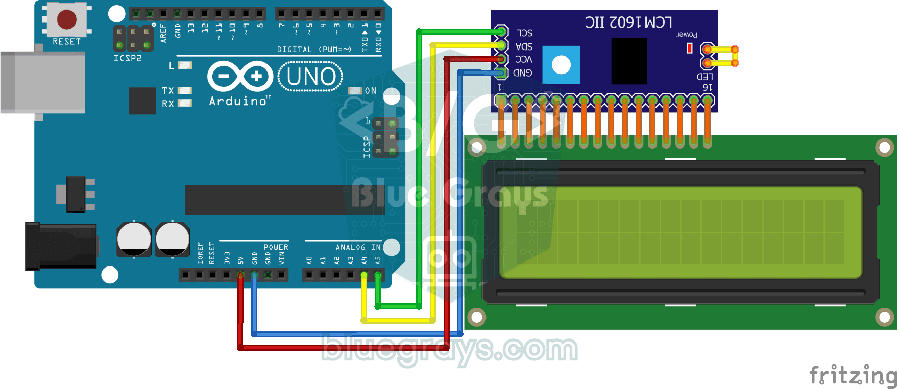
Using LCD Screen with I2C
Give your Arduino its own screen and make it write its first message. The two-line LCD screen hooks up with just a few wires; a greeting appears on the top line, then a second message on the bottom…

ESP32 I2C LCD Display (16x2)
In this project we connect a 16x2 character LCD to the ESP32 over I2C and display text. With I2C, just 2 data pins (SDA and SCL) control the screen, instead of the 6+ pins a classic parallel connection wastes. The code prints a fixed message on the first line and a counter that goes up every second on the second. At startup an I2C scanner also prints the display's address to the Serial Monitor (usually 0x27 or 0x3F).

ESP32 HTTPClient + Weather API (with SSD1306 OLED Display)
In this project the ESP32 makes a REST API call over the internet to a weather API (wttr.in) using HTTPClient.h. Unlike the I2C LCD version, it uses an SSD1306 OLED (128×64) display, with large text and vector icons for a richer look. Seven weather icons (sunny, rainy, snowy and more) are drawn on the fly, with no bitmap files.

ESP32 Deep Sleep — Battery Saving (OLED + RTC RAM Counter)
The ESP32's Deep Sleep mode shuts down the CPU and most peripherals, cutting current draw to about 10µA, which is vital for battery-powered IoT devices. This project uses three wake-up sources: a timer (15 s), an external pin (EXT0, the button on GPIO 33) and a touch pin (T0/GPIO 4). Counters marked with RTC_DATA_ATTR survive deep sleep.
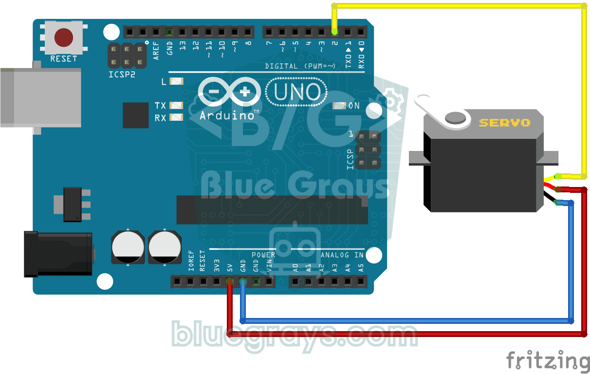
Using a Servo Motor
The arm of a small servo motor turns to three positions in turn: all the way to the start, right to the middle and all the way to the end, waiting two seconds at each stop.
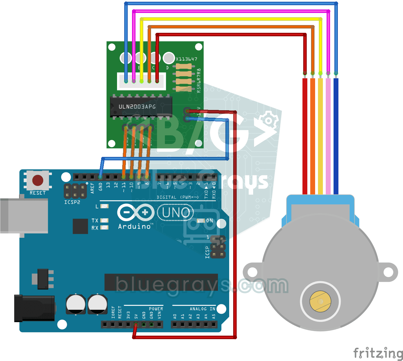
Using a Stepper Motor
A motor that turns step by step, exactly as far as you want, like the hand of a clock.

Bluetooth Controlled Car with L298N
Turn your phone into a remote and drive your own robot car. The Arduino receives commands from a remote-control app on your phone through a Bluetooth module and spins the wheels with a motor driver…

Obstacle Avoidance Robot
How about building a smart vehicle that finds its own way? The Obstacle Avoidance Robot constantly scans its surroundings thanks to the ultrasonic sensor in front of it.