
Arduino I2C Master Slave: Connect Two Arduinos, Send Structs
Arduino I2C master slave: wiring two Arduinos, pull-up values, Wire.onReceive and onRequest, picking an address, sending structs and ESP32 level shifting.

An Arduino I2C master slave setup is one of the most practical ways to connect two boards: it needs only two data wires (SDA and SCL) plus a shared ground, and it takes just a few lines with the Wire library that ships with Arduino. One board is the controller (formerly called the master) and always starts the conversation; the other is the target (the slave), which has an address and either listens to what it's sent or answers when asked. Because dozens of targets can share the same two wires, I2C is very handy in projects where one main board manages several helper Arduinos.
In this article we connect two Arduino Unos over I2C step by step: a wiring and pull-up table, choosing an address, the Wire.onReceive and Wire.onRequest functions, sending a single byte, two-way data exchange with a struct, several Arduinos on one bus, talking to an ESP32 and a Raspberry Pi Pico through a level shifter, and an I2C vs UART comparison. If you want to brush up on I2C basics and the scanner sketch first, take a look at What Is I2C?.
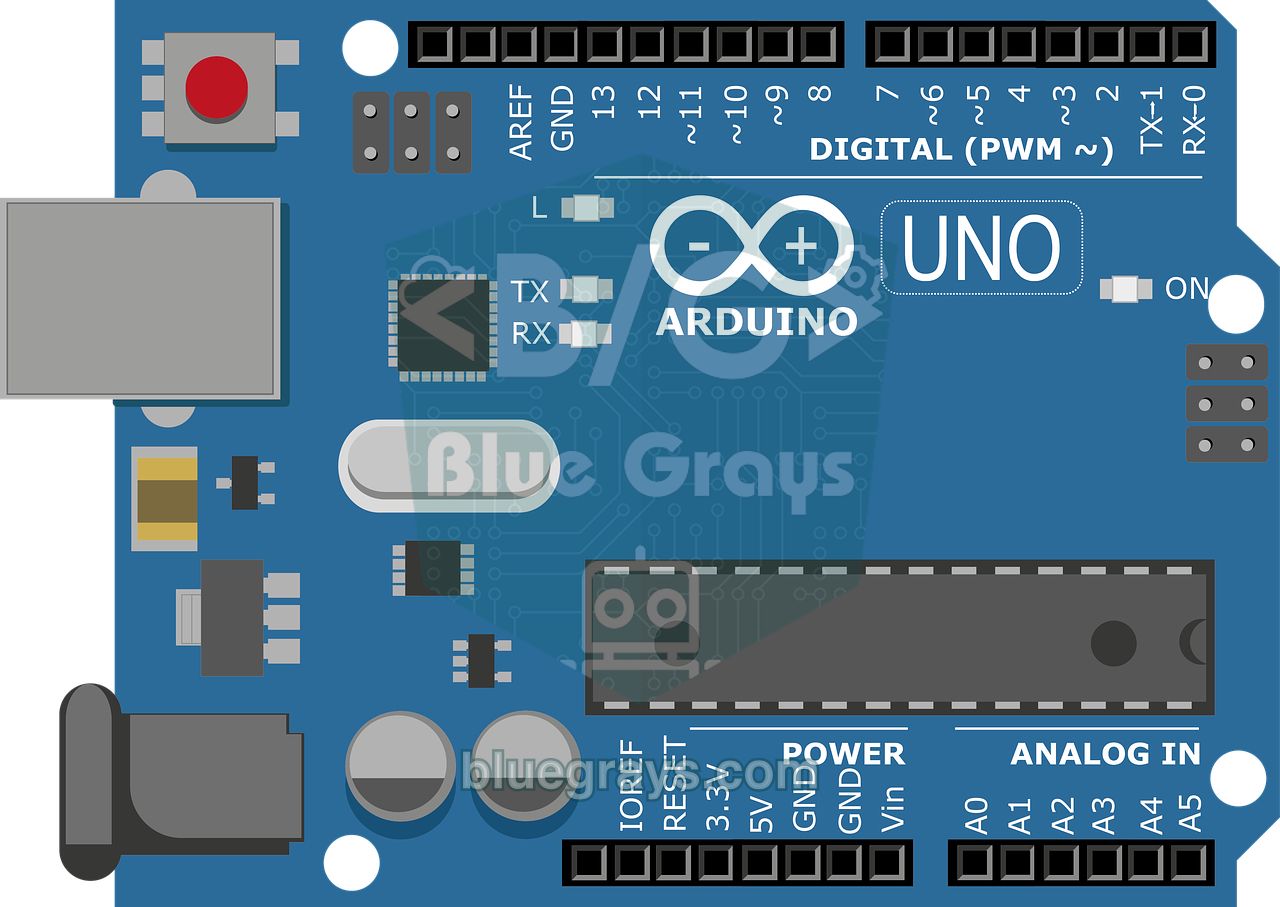
How do the controller and target (master and slave) work in I2C?
In I2C every device is wired in parallel to the same two lines. SCL is the clock line, and the controller always drives it; SDA is the data line and carries data in both directions. To start a message, the controller creates a "start" condition and then sends the target's 7-bit address together with a read or write bit. The target with that address answers with an ACK (got it) by pulling the line LOW briefly at the end of each byte; if nobody has that address, the line stays HIGH, which is called a NACK. That's why in I2C the controller knows immediately whether a message arrived. The most important rule is this: a target can't speak on its own. Even when it has new data, it waits until the controller asks, so the controller has to poll it regularly. Arduino's documentation calls these roles "controller" and "peripheral", and the newer revision of the I2C standard uses "controller" and "target"; they mean the same thing as master and slave in older code.
Wiring: the I2C connections between two Arduinos
| Arduino A (controller) | Connection | Arduino B (target) | Note |
|---|---|---|---|
| A4 (SDA) | Direct | A4 (SDA) | Not crossed |
| A5 (SCL) | Direct | A5 (SCL) | Not crossed |
| GND | Direct | GND | Required: common reference |
| 5V | Optional | 5V | Only if board B is powered from board A |
| SDA and SCL | 4.7 kΩ to 5V | - | One pair of resistors is enough for the whole bus |
| Board | SDA | SCL | Note |
|---|---|---|---|
| Arduino Uno / Nano | A4 | A5 | On the Uno R3, the SDA and SCL pins next to AREF are the same bus |
| Arduino Mega 2560 | D20 | D21 | Has 10 kΩ pull-up resistors on the board |
| Arduino Leonardo / Micro | D2 | D3 | Different pins from the Uno |
| ESP32 | GPIO 21 | GPIO 22 | 3.3 V; Wire.begin(sda, scl) lets you pick other pins |
| Raspberry Pi Pico | GP4 (I2C0) | GP5 (I2C0) | 3.3 V; MicroPython lets you pick other pin pairs |
Pull-up resistors: when do you need them and what value?
Devices on an I2C bus can only pull the lines LOW; what brings them back HIGH are the pull-up resistors. On Arduino's AVR boards, Wire.begin() turns on internal pull-ups of roughly 20–50 kΩ on SDA and SCL. With two Unos, short wires and 100 kHz that usually works, but those resistors are weak for I2C; as the wires get longer the rising edges slow down and errors start. For a reliable bus, add one 4.7 kΩ resistor from SDA to 5V and another from SCL to 5V. The lower limit comes from the 3 mA allowed in the LOW state: R(min) = (5 V - 0.4 V) / 3 mA ≈ 1.5 kΩ. The upper limit is set by the bus capacitance: at 100 kHz, for a 200 pF bus, R(max) ≈ 1000 ns / (0.8473 × 200 pF) ≈ 5.9 kΩ. Use the Ohm's Law tool for the math and Pull-up and Pull-down Resistors for the idea behind them.
| Situation | Recommended pull-up | Note |
|---|---|---|
| Two Unos, wires under 30 cm, 100 kHz | 4.7 kΩ (the internal ones often work too) | The most common setup |
| 50 cm to 1 m of wire, or 400 kHz | 2.2 kΩ | Still keep the wires as short as possible |
| An Arduino Mega is on the bus | You may not need any more | The Mega's 10 kΩ resistors end up in parallel with the others |
| Modules with pull-ups on the bus (OLED, RTC, LCD) | Work out the total parallel resistance | The total shouldn't drop below 1.5 kΩ |
| Arduino with ESP32 or Pico | The level shifter's resistors on each side | Don't connect them directly; see the section below |
Choosing an address: which one should you use?
You choose the target Arduino's address yourself with Wire.begin(address). In the 7-bit address space, 0x00–0x07 and 0x78–0x7F are reserved, so the range you can use is 0x08–0x77, or 8 to 119 in decimal. If there are other modules on the bus, pick a value that doesn't clash with theirs; the safest approach is to connect everything and run the I2C scanner to see which addresses are taken. These are the addresses of common modules:
| Address | Modules that often use it |
|---|---|
| 0x27 / 0x3F | I2C LCD with a PCF8574 backpack |
| 0x3C / 0x3D | SSD1306 OLED display |
| 0x68 | DS1307 and DS3231 RTCs, MPU-6050 |
| 0x76 / 0x77 | BMP280 and BME280 |
| 0x40 | PCA9685 servo driver, INA219 |
| 0x48 | ADS1115 ADC |
| 0x57 | MAX30102, the AT24C32 EEPROM on RTC modules |
| 0x08–0x0F | Usually unused; a good range for Arduino targets |
Example 1: sending a byte from the controller to the target
In the first example, board A reads a potentiometer on A0, divides the value by 4 to bring it into the 0–255 range, and sends it 10 times a second as a single byte to address 8. Board B receives the byte and sets the brightness of the LED on D9. Upload the controller sketch to board A first, then the target sketch to board B. The Wire library comes with the Arduino IDE, so there's nothing to install. Controller sketch:
1// Denetleyici (master): potansiyometre değerini hedefe gönderir / Controller (master): sends the pot value to the target
2#include <Wire.h>
3
4const byte TARGET_ADDR = 8;          // hedef kartın adresi / address of the target board
5
6void setup() {
7  Wire.begin();                      // adres verilmedi = denetleyici / no address = controller
8  Serial.begin(9600);
9}
10
11void loop() {
12  byte value = analogRead(A0) / 4;   // 0-1023 -> 0-255
13  Wire.beginTransmission(TARGET_ADDR);
14  Wire.write(value);
15  byte status = Wire.endTransmission();   // 0 = başarılı / 0 = success
16  if (status != 0) {
17    Serial.print(F("I2C hatasi / error: "));
18    Serial.println(status);          // 2 = adres yanıt vermedi / 2 = no ACK on address
19  }
20  delay(100);
21}
Target sketch to upload to board B:
1// Hedef (slave): gelen baytla LED parlaklığını ayarlar / Target (slave): sets the LED brightness from the received byte
2#include <Wire.h>
3
4const byte MY_ADDR = 8;              // bu kartın adresi / this board's address
5const int LED_PIN = 9;               // PWM pini / PWM pin
6
7volatile byte received = 0;
8volatile bool newData = false;
9
10void onReceiveEvent(int howMany) {   // kesme içinde çalışır: kısa tut / runs inside an interrupt: keep it short
11  for (int i = 0; i < howMany; i++) received = Wire.read();   // son bayt kalır / keep the last byte
12  newData = true;
13}
14
15void setup() {
16  Wire.begin(MY_ADDR);               // adresle başlat = hedef / start with an address = target
17  Wire.onReceive(onReceiveEvent);
18  pinMode(LED_PIN, OUTPUT);
19  Serial.begin(9600);
20}
21
22void loop() {
23  if (newData) {
24    newData = false;
25    analogWrite(LED_PIN, received);
26    Serial.println(received);        // Serial'ı kesmenin dışında kullan / use Serial outside the interrupt
27  }
28}
The target sketch has two key points. The first is Wire.begin(8): a board started with an address becomes a target. The second is Wire.onReceive(): when the controller sends data, the Wire library calls this function by itself and passes it the number of bytes received. We store the value in a volatile variable and just raise a "new data" flag; setting the LED and printing to the Serial Monitor happen in loop(). On the controller, the value returned by Wire.endTransmission() tells you what happened to the message:
| endTransmission() value | Meaning | What to do |
|---|---|---|
| 0 | Success, the target acknowledged every byte | - |
| 1 | Data too long for the buffer (more than 32 bytes) | Split the message into parts |
| 2 | No ACK on the address | Check the address, the wiring, GND and that the target is powered |
| 3 | No ACK on a data byte | The target is busy or got an unexpected length |
| 4 | Other error | The bus may be noisy or missing pull-ups |
| 5 | Timeout | The bus hung; enable recovery with setWireTimeout() |
onReceive and onRequest: rules inside the interrupt
- Keep them short: Both functions run inside the I2C interrupt. Don't use delay(), Serial.print() or long calculations there; store the data in a variable and return.
- Use volatile: Declare flags that change in the interrupt and are read in loop() as volatile; otherwise the compiler may not see the change. For details, see Arduino Interrupts.
- Write everything at once in onRequest: When the controller asks for data, put all the bytes into the buffer with a single Wire.write(array, length). Have the data ready in advance; reading a sensor inside onRequest keeps the controller waiting.
- The 32-byte limit: The Wire buffer on AVR is 32 bytes. Split longer data across several messages, or use UART if you really need to.
- Check the length: Compare the number of bytes arriving in onReceive with what you expect; if there are too many or too few, read them out and discard them.
- Prepare the answer ahead of time: Update the report variables before the target starts a long task, so the controller always finds an answer ready.
Example 2: two-way communication with a struct
Real projects need more than one byte: the controller sends a command and the target returns a report with several values. Instead of splitting the values into bytes by hand, it's cleaner and faster to define a struct and send it as is. In the example below, the controller sets the LED and its brightness with a 2-byte command, then uses Wire.requestFrom() to ask the target for a 7-byte report: the potentiometer value (uint16_t), the button state (uint8_t) and the target's uptime (uint32_t). The structs must be identical on both boards. Controller sketch:
1// Denetleyici: komut gönderir, rapor ister / Controller: sends a command, requests a report
2#include <Wire.h>
3
4struct __attribute__((packed)) Command {   // denetleyici -> hedef / controller -> target (2 bayt / bytes)
5  uint8_t ledOn;
6  uint8_t brightness;
7};
8
9struct __attribute__((packed)) Report {    // hedef -> denetleyici / target -> controller (7 bayt / bytes)
10  uint16_t potValue;
11  uint8_t buttonPressed;
12  uint32_t uptimeMs;
13};
14
15const byte TARGET_ADDR = 8;
16
17void setup() {
18  Wire.begin();
19  Wire.setClock(100000);                   // standart hız 100 kHz / standard mode 100 kHz
20  Wire.setWireTimeout(25000, true);        // hat takılırsa 25 ms'de kurtul / recover if the bus hangs for 25 ms
21  Serial.begin(9600);
22}
23
24void loop() {
25  Command cmd;
26  cmd.ledOn = 1;
27  cmd.brightness = (millis() / 20) % 256;  // yavaşça artan parlaklık / slowly rising brightness
28
29  Wire.beginTransmission(TARGET_ADDR);
30  Wire.write((const uint8_t*)&cmd, sizeof(cmd));
31  byte err = Wire.endTransmission();
32
33  Report r;
34  byte n = Wire.requestFrom(TARGET_ADDR, (byte)sizeof(Report));
35  if (err == 0 && n == sizeof(Report)) {
36    Wire.readBytes((uint8_t*)&r, sizeof(r));
37    Serial.print(F("Pot: "));
38    Serial.print(r.potValue);
39    Serial.print(F("  Buton / button: "));
40    Serial.print(r.buttonPressed);
41    Serial.print(F("  Sure / uptime ms: "));
42    Serial.println(r.uptimeMs);
43  } else {
44    while (Wire.available()) Wire.read();  // yarım veriyi at / drop partial data
45    Serial.println(F("Hedef yanit vermedi / target not responding"));
46  }
47  delay(200);
48}
The target board's sketch; the struct definitions are exactly the same as on the controller:
1// Hedef: komutu uygular, istenince rapor gönderir / Target: applies the command, sends a report on request
2#include <Wire.h>
3
4struct __attribute__((packed)) Command {   // denetleyicideki yapının aynısı / same struct as on the controller
5  uint8_t ledOn;
6  uint8_t brightness;
7};
8
9struct __attribute__((packed)) Report {
10  uint16_t potValue;
11  uint8_t buttonPressed;
12  uint32_t uptimeMs;
13};
14
15const byte MY_ADDR = 8;
16const int LED_PIN = 9;
17const int BUTTON_PIN = 2;
18
19Command cmd;
20Report report;
21volatile bool newCmd = false;
22
23void onReceiveEvent(int howMany) {
24  if (howMany != sizeof(Command)) {        // beklenmeyen uzunluk: at / unexpected length: discard
25    while (Wire.available()) Wire.read();
26    return;
27  }
28  Wire.readBytes((uint8_t*)&cmd, sizeof(cmd));
29  newCmd = true;
30}
31
32void onRequestEvent() {                    // denetleyici veri istedi / the controller asked for data
33  Wire.write((const uint8_t*)&report, sizeof(report));   // tek seferde yaz / write it in one go
34}
35
36void setup() {
37  pinMode(LED_PIN, OUTPUT);
38  pinMode(BUTTON_PIN, INPUT_PULLUP);
39  Wire.begin(MY_ADDR);
40  Wire.onReceive(onReceiveEvent);
41  Wire.onRequest(onRequestEvent);
42}
43
44void loop() {
45  uint16_t pot = analogRead(A0);
46  uint8_t pressed = (digitalRead(BUTTON_PIN) == LOW);
47  uint32_t now = millis();
48
49  noInterrupts();                          // kopyalarken onRequest araya girmesin / keep onRequest out while copying
50  report.potValue = pot;
51  report.buttonPressed = pressed;
52  report.uptimeMs = now;
53  Command c = cmd;
54  bool fresh = newCmd;
55  newCmd = false;
56  interrupts();
57
58  if (fresh) analogWrite(LED_PIN, c.ledOn ? c.brightness : 0);
59}
In the target sketch, the function registered with Wire.onRequest() sends the report struct as is whenever the controller asks for data. The report itself is updated in loop(). While it's being updated, we pause interrupts for a moment with noInterrupts(), so if the controller asks at exactly that instant it doesn't get a value that's half old and half new. The incoming command is also copied into a local variable inside the same protection. On the controller, the line Wire.setWireTimeout(25000, true) stops the bus from locking up forever if a wire comes loose or the target hangs: if there's no answer within 25 ms, Wire resets itself.
Connecting several Arduinos to the same bus
I2C's big advantage over UART is that many targets can share the same two wires. Give each target board its own address (for example 8, 9 and 10), join all the SDAs, all the SCLs and all the GNDs, and use a single pair of pull-up resistors for the whole bus. The controller can loop through an array of addresses, sending each board a command and asking for its report. The longer the bus, the more capacitance it has; keep the boards close together, keep the total wire length to a few tens of centimeters and, if needed, stick to 100 kHz. You can also put modules like an I2C LCD or an OLED on the same bus; as long as the addresses don't clash, everything works together fine.
I2C between Arduino and ESP32: level shifting
The Arduino Uno runs at 5 V and the ESP32 at 3.3 V, and the ESP32's pins aren't 5 V tolerant. Since Wire.begin() on the Uno ties the internal pull-ups to 5 V, connecting the two boards directly pulls the ESP32's pins up to 5 V. The other way round is a problem too: if you pull the bus up to only 3.3 V, the Uno's I2C inputs need at least 0.7 × 5 V = 3.5 V to read HIGH, and 3.3 V falls short. The right fix is a bidirectional BSS138 level shifter with pull-up resistors on both sides: the HV side goes to the Uno's 5V and A4/A5, the LV side to the ESP32's 3V3 and GPIO 21/22, and the GNDs are shared. For detailed wiring, see Logic Level Converter. The ESP32 can also act as a target from core version 2.0.1 on, but preparing data right at onRequest time is harder on the ESP32, so the least troublesome setup is the ESP32 as controller and the Uno as target. The sketch below reads the same report from the Uno target in Example 2:
1// ESP32 denetleyici, Arduino Uno hedeften rapor okur / ESP32 controller reads the report from an Arduino Uno target
2#include <Wire.h>
3
4struct __attribute__((packed)) Report {    // Uno'daki yapıyla birebir aynı / exactly the same as on the Uno
5  uint16_t potValue;
6  uint8_t buttonPressed;
7  uint32_t uptimeMs;
8};
9
10const uint8_t TARGET_ADDR = 8;
11
12void setup() {
13  Serial.begin(115200);
14  Wire.begin(21, 22);                      // SDA = GPIO 21, SCL = GPIO 22 (seviye dönüştürücü üzerinden / through a level shifter)
15  Wire.setClock(100000);
16}
17
18void loop() {
19  Report r;
20  uint8_t n = Wire.requestFrom(TARGET_ADDR, (uint8_t)sizeof(Report));
21  if (n == sizeof(Report)) {
22    Wire.readBytes((uint8_t*)&r, sizeof(r));
23    Serial.printf("Pot: %u  Buton / button: %u  Sure / uptime: %lu ms\n",
24                  (unsigned int)r.potValue, (unsigned int)r.buttonPressed, (unsigned long)r.uptimeMs);
25  } else {
26    Serial.println("Uno yanit vermedi / Uno not responding");
27  }
28  delay(500);
29}
I2C controller on the Raspberry Pi Pico (MicroPython)
The Raspberry Pi Pico also runs at 3.3 V, so it connects to the Uno the same way, through a level shifter. MicroPython doesn't have C structs, but the struct module does the same job: the format "<HBI" means a little-endian, unpadded uint16_t, uint8_t and uint32_t, which matches the Uno's 7-byte report exactly. The code first scans the bus and prints the addresses it finds, then sends a command to the Uno target and reads its report. If you're new to the Pico, start with What Is the Raspberry Pi Pico?.
1from machine import I2C, Pin
2import struct, time
3
4i2c = I2C(0, sda=Pin(4), scl=Pin(5), freq=100000)   # seviye dönüştürücü üzerinden / through a level shifter
5print("Bulunan adresler / found:", [hex(a) for a in i2c.scan()])
6
7while True:
8    i2c.writeto(8, bytes([1, 128]))                  # Command: ledOn = 1, brightness = 128
9    data = i2c.readfrom(8, 7)                        # Report: 7 bayt / 7 bytes
10    pot, button, uptime = struct.unpack("<HBI", data)   # küçük endian, dolgusuz / little-endian, no padding
11    print("Pot:", pot, "Buton:", button, "ms:", uptime)
12    time.sleep(0.5)
I2C or UART? A comparison
| Feature | I2C | UART |
|---|---|---|
| Wires | SDA, SCL and GND (straight) | TX, RX and GND (crossed) |
| Number of devices | One controller and up to 112 addresses | Only two devices |
| Who starts the conversation? | Only the controller | Either side, whenever it wants |
| Typical speed | 100 kHz or 400 kHz | 9600–115200 baud |
| Distance | On-board and short wires (up to 1 m) | A few meters; much farther with RS-485 |
| Delivery confirmation | Yes (ACK and NACK) | No; you have to add your own check |
| Message size (Wire) | 32-byte buffer | Continuous stream of bytes |
| Hardware on the Arduino Uno | A4 and A5 | D0 and D1 (shared with USB) or SoftwareSerial |
In short: choose I2C when the boards are in the same enclosure, when one main board will manage several helpers and when you want to be sure each message arrived. If the boards are several meters apart, if both sides need to send data whenever they like, or if there's a long, continuous data stream, UART is the better fit; the details are in UART Serial Communication. If you need a lot of speed, the third option is SPI.
Common mistakes and how to fix them
- endTransmission() returns 2: The target isn't answering at that address. Check that the address is the same in both sketches, that SDA and SCL aren't swapped, that GND is connected and that the target sketch is uploaded; confirm the address with the I2C scanner.
- Crossing SDA and SCL like UART: In I2C, SDA goes to SDA and SCL to SCL; with crossed wires no device is found.
- The program freezes inside onReceive: The interrupt function uses Serial.print() or delay(), or starts another Wire transaction. Only copy the data there and do the work in loop().
- The values arrive scrambled or shifted: The struct definitions differ between the boards, a type like int whose size depends on the board was used, or packed is missing. Use fixed-size types and the same definition.
- Random errors once the wires get longer: The internal pull-ups aren't enough. Add external 4.7 kΩ or 2.2 kΩ resistors, shorten the wires and keep the speed at 100 kHz.
- The bus stops working or the ESP32 gets warm once it's connected: 5 V and 3.3 V were connected directly. Put a bidirectional level shifter in between.
Getting two Arduinos to talk over I2C is the easiest way to break a big project into small, independent parts: one board handles the display and the user while the others read sensors or drive motors. First confirm the link with the single-byte example, then move on to the two-way struct example. In the BlueGrays app you'll find wiring diagrams and step-by-step code for the one-way and two-way 2-Arduino communication projects, the I2C LCD, the I2C calculator, the ESP32 I2C LCD and the DS1307 RTC clock.
Frequently asked questions
How do two Arduinos communicate over I2C?
Connect the A4 (SDA), A5 (SCL) and GND pins of the two boards directly. One board starts as the controller with Wire.begin(), the other as a target with an address such as Wire.begin(8). The controller sends data with beginTransmission, write and endTransmission and asks for data with requestFrom; the target answers through its onReceive and onRequest functions.
Do I need pull-up resistors for I2C between two Arduinos?
Yes; I2C lines are open-drain, so the HIGH level comes from pull-up resistors. The Arduino's internal pull-ups often work with two boards and short wires, but for a reliable bus it's recommended to add 4.7 kΩ from SDA and from SCL to 5V.
How many Arduinos can be connected on one I2C bus?
With 7-bit addressing, 112 addresses from 0x08 to 0x77 are usable, so in theory 112 targets fit. In practice the limit is set by the total bus capacitance and wire length; with a handful of boards and short wires you won't have any problems.
Can an Arduino slave send data to the master on its own?
No. In I2C the controller always starts the communication; the target only answers through onRequest when it's asked. If the target needs to signal that it has new data, the controller polls it regularly, or the target pulls a separate interrupt pin LOW to alert the controller.
Can I connect an Arduino and an ESP32 directly over I2C?
It isn't recommended. The Uno runs at 5 V and the ESP32 at 3.3 V, and the Uno's internal pull-ups pull the ESP32's pins up to 5 V. Use a bidirectional level shifter such as the BSS138 and make the ESP32 the controller and the Uno the target.
What is the difference between I2C and UART on Arduino?
I2C puts many devices on the same bus with two wires and addresses, and confirms with an ACK that each byte arrived, but only the controller can start a conversation. UART links only two devices, its wires are crossed, and either side can send data whenever it wants. I2C suits several boards close together; UART suits long wires and continuous data streams.
Projects to build after reading this
See all projects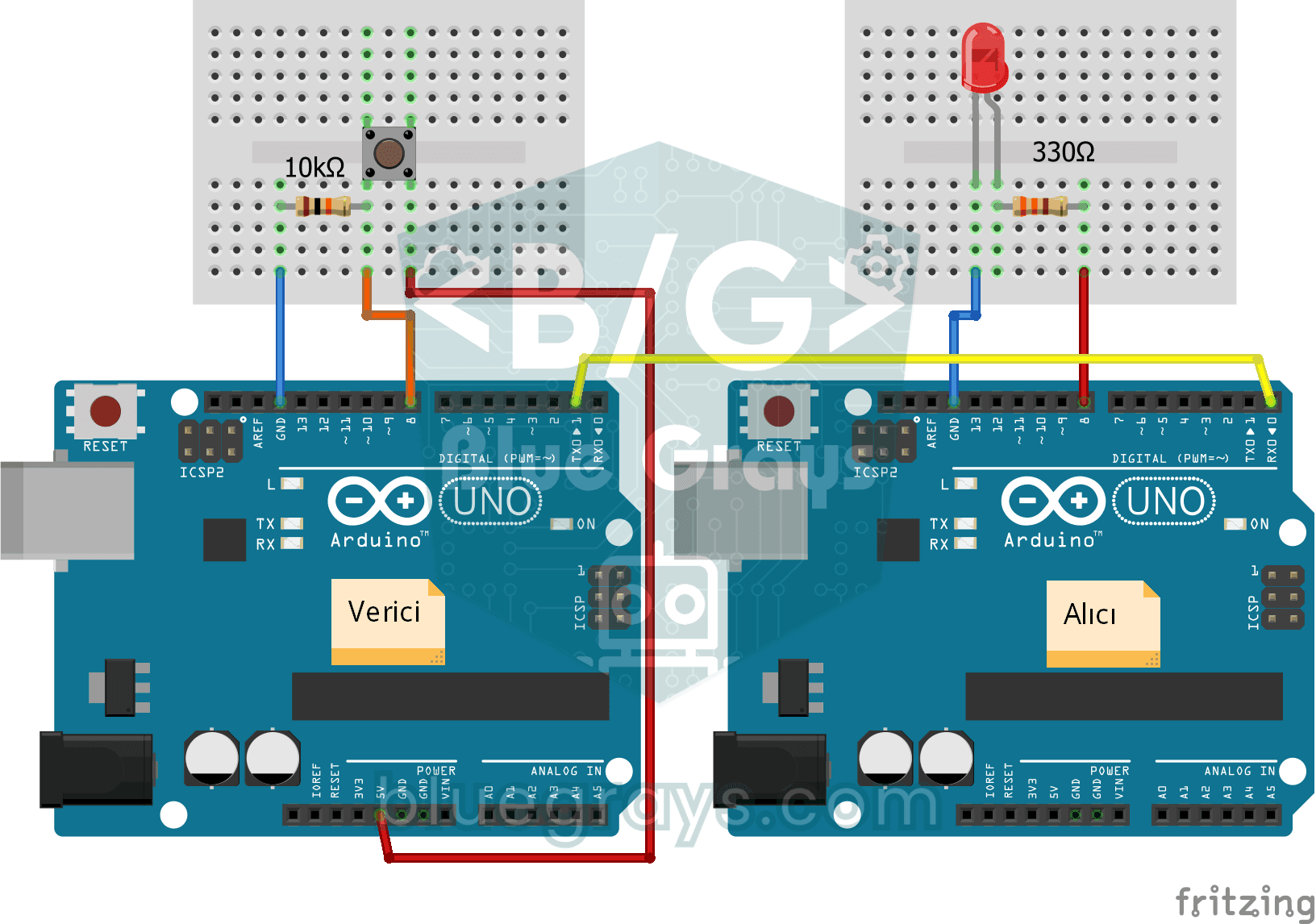
One-Way Communication Between 2 Arduinos
You get two Arduinos talking over a single wire: press the button on one and the LED on the other lights up, press it again and it goes off.
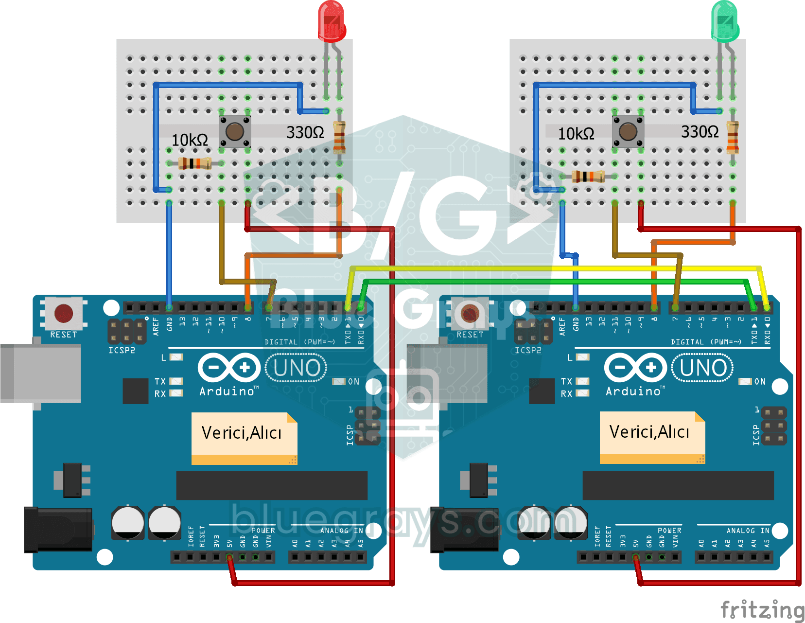
Two-Way Communication Between 2 Arduinos
Two Arduinos are wired together and talk to each other: press the button on one and the light on the other comes on, press it again and it goes off.
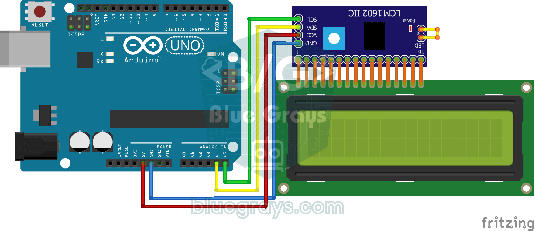
Using LCD Screen with I2C
Give your Arduino its own screen and make it write its first message. The two-line LCD screen hooks up with just a few wires; a greeting appears on the top line, then a second message on the bottom…

Arduino I2C Calculator
It is an Arduino-based calculator project that performs addition, subtraction, multiplication and division operations using a 4x4 membrane keypad and a 16x2 I2C LCD display. Thanks to I2C, the display connection is provided with only 2 cables, thus reducing cable clutter and keeping more pins open for use. There is also decimal number input and negative number support.

ESP32 I2C LCD Display (16x2)
In this project we connect a 16x2 character LCD to the ESP32 over I2C and display text. With I2C, just 2 data pins (SDA and SCL) control the screen, instead of the 6+ pins a classic parallel connection wastes. The code prints a fixed message on the first line and a counter that goes up every second on the second. At startup an I2C scanner also prints the display's address to the Serial Monitor (usually 0x27 or 0x3F).

Digital Clock with ESP32 and DS1307 RTC (I2C + LCD)
In this project, we display the time and date on a 16x2 I2C LCD screen using the DS1307 real-time clock (RTC) module. The DS1307 is a battery-backed RTC that maintains the time even if the ESP32 is powered off. Both modules share the same I2C bus (SDA/SCL), allowing us to learn how to control multiple devices using just two signal wires. Through this project, you will gain practical knowledge of the I2C communication protocol, RTC module operation, and dynamic data display on an LCD screen.

Paddle Ball Game - SSD1306
A ball, two paddles and you: you play table tennis, one of the very first video games, on a small OLED screen.

Dot Matrix Clock and Calendar (MAX7219, DS1307)
A glowing board for your desk or wall that shows the time and date in scrolling text.