
Electronics Lab Safety Rules for Students: 10 Rules and Checklist
Electronics lab safety rules for students: a 10-rule classroom poster, risk table, lithium battery and soldering rules, motor power and a teacher checklist.
Start your electronics lab safety rules for students with a realistic picture: Arduino, ESP32 and Raspberry Pi Pico projects powered at 5 V or 3.3 V from a computer's USB port are generally low risk, because these voltages do not push a noticeable current through dry skin. The real risks are elsewhere: wires and parts heating up in a short circuit, lithium batteries (18650, LiPo), the hot tip and fumes of a soldering iron, flying lead clippings and small parts, and mains voltage (220–240 V, or 120 V in North America). The core of this article fits in one sentence: student projects never touch mains voltage; every other risk is managed with a few clear rules, a checklist and habits repeated in every lesson. Below you will find a 10-rule list to put on the classroom wall and a teacher checklist for before and after class.
We gave safety a short section when setting up a school lab: the school Arduino lab article covers the 5 V limit, battery storage and an 8-rule poster for the door. This article picks up from there and opens each risk on its own: how it happens and its first signs, how to explain each rule to students, lithium battery and soldering station rules, the order for connecting an external power supply for motors, the mains limit, before and after class checklists and what to do if something happens. The end-of-lesson pack-up routine for a large class is in the Arduino lesson in a large class article, so we do not repeat it here.
The real risk is not voltage: heat, energy and haste
Students and parents often ask, "can it give you a shock?" At 5 V the answer is no, but that does not make a circuit harmless. Harm usually comes from heat, and heat depends on current, not voltage. If a jumper wire connects 5V straight to GND, the resistance in the path is almost zero and the source delivers as much current as it can. The computer's USB port and the 500 mA resettable fuse on the Arduino Uno limit that current, so a short on USB usually ends with the port shutting down. Make the same mistake with an 18650 cell and things change: lithium cells can deliver tens of amps into a short, a thin wire heats up within seconds and its insulation melts. In a classroom, risk grows with the size of the power source: USB, then an AA battery pack, then a bench power supply, then a lithium battery and finally the mains. Set how strict your rules are in the same order.
| Risk | How it happens | First sign | Prevention |
|---|---|---|---|
| Short circuit and heat | A wire joins 5V and GND, a module is plugged in with VCC and GND swapped, a lead slips into the next breadboard row | The board or module gets warm, the ON light goes out or flickers, the computer disables the USB device | Unplug USB while rewiring; trace the 5V and GND lines before powering; read the VCC and GND labels on the module |
| LED without resistor, too much pin current | An LED goes straight to a pin, or a motor or relay coil is driven from a pin | The LED flashes very bright and dies, the pin stops working, the board keeps resetting | A series resistor for every LED (220–330 Ω at 5 V); stay under 20 mA per pin; drive loads through a driver |
| Lithium battery | A swollen or crushed cell, unattended charging, a bare 18650 carried in a pocket with keys | The battery gets warm, swells, smells or hisses | Charge only under supervision; store in a closed, non-flammable box; never use a swollen battery |
| Soldering | The iron tip is above 300 °C; an iron left off its stand; flux fumes | Minor burn, irritated eyes and throat | Iron stand, ventilation, safety glasses, teacher supervision |
| Sharp leads, small parts | Clipped leads flying off, parts dropped on the floor, coin cells left lying around | Something in an eye, a scratch, missing parts | Safety glasses; hold the lead end while cutting; keep coin cells counted and in their packaging |
| Reversed electrolytic capacitor | Polarity reversed or a voltage rating lower than the circuit | The capacitor bulges and can pop open | Long lead +, striped side −; voltage rating at least 1.5–2 times the circuit voltage; safety glasses |
| Laser module | The beam is pointed at someone's eyes | Dazzle, risk of eye damage | Point the beam only at a target on the wall; never at eye level |
| Mains voltage (220–240 V / 120 V) | Switching a plugged-in appliance with a relay, an open AC-DC converter module | Electric shock, fire | No mains in student projects; relays switch only low-voltage loads |
10 safety rules for the classroom wall
Rules should be short, written as instructions and easy to check by eye: "be careful" is not a rule, "unplug USB before you change a wire" is. Print the 10 rules below in large type on an A3 sheet and hang them next to the teacher's desk. In the first lesson read the rules in order, explain each one with the single sentence from the next table, and ask students to restate one rule in their own words. The lab poster focused on boxes and desks; this list focuses on the decisions made at the circuit itself. You can hang both side by side.
- The board's USB cable is unplugged whenever you add, remove or move a wire.
- Before powering up, trace the 5V, 3V3 and GND lines with your finger; your partner checks too.
- Connect every LED with a resistor; never drive a motor, relay coil or speaker directly from an Arduino pin.
- If something gets hot, smells, hisses or smokes, pull the USB cable, step back and raise your hand.
- Use batteries, adapters and power supplies only with the teacher's permission; never carry a bare lithium cell.
- Never connect anything that plugs into the wall to your circuit: there is no mains voltage in this lab.
- The soldering iron is used only at the soldering station, with safety glasses and with the teacher present; when it is not in your hand, it is in its stand.
- Wear safety glasses when cutting leads, hold the end you are cutting off and put it in the bin.
- Never point a laser or a bright LED at anyone's eyes; no food or drink on the desks.
- Do not keep or try to fix a broken, hot or swollen part; hand it to the teacher.
The reason behind each rule, in one sentence
A rule without a reason is forgotten at the first boring moment. The sentences in the table are written for ages 10–15; with older students you can also discuss the numbers behind them. Do the short demonstrations in the third column yourself while students watch; none of them involves a real short circuit or a real burn risk.
| Rule | One sentence for students | Short demo (done by the teacher) |
|---|---|---|
| 1. Unplug USB | If you rewire with USB plugged in and one end touches the wrong hole, the short happens instantly. | With USB unplugged, add a wrong wire joining 5V and GND and let the multimeter's continuity beep "announce" the short. |
| 2. Trace the lines | A one-minute check is cheaper than a burnt board. | Put the circuit diagram next to the circuit and count the wires one by one. |
| 3. Resistor and pin | A resistor limits current; an Arduino pin is only strong enough for a small LED. | In the LED resistor tool enter 5 V, a red LED and 15 mA and show the 220 Ω result. |
| 4. Hot means stop | Heat is the earliest sign that something is wrong; cutting the power first makes everything after it easier. | Rehearse "pull, step back, hand up" once with the class. |
| 5. Batteries with permission | A battery has no fuse and delivers far more current into a short than USB. | Show a battery box with a lid and an 18650 with taped terminals. |
| 6. No mains | Mains voltage can give a dangerous shock and start a fire; the only power here is 5 V. | Show the bare solder joints under an unplugged relay module: on the mains all of them would be live. |
| 7. Iron in its stand | The tip of a soldering iron is hotter than the highest setting of a kitchen oven. | With a cold iron, show how to put it in the stand and why you never catch a falling iron. |
| 8. Safety glasses | A clipped lead flies off fast and the eyes are the easiest target. | Cut a lead pointing into the bin while holding the end with your finger. |
| 9. Laser and desk | A laser beam can damage eyes; water on the desk can spill into the circuit. | Point the laser module at a paper target on the wall. |
| 10. Hand in broken parts | A broken part left on the desk looks fine to the next group. | Show the red-labelled "faulty" box and where it lives. |
Lithium battery rules: 18650, LiPo and TP4056
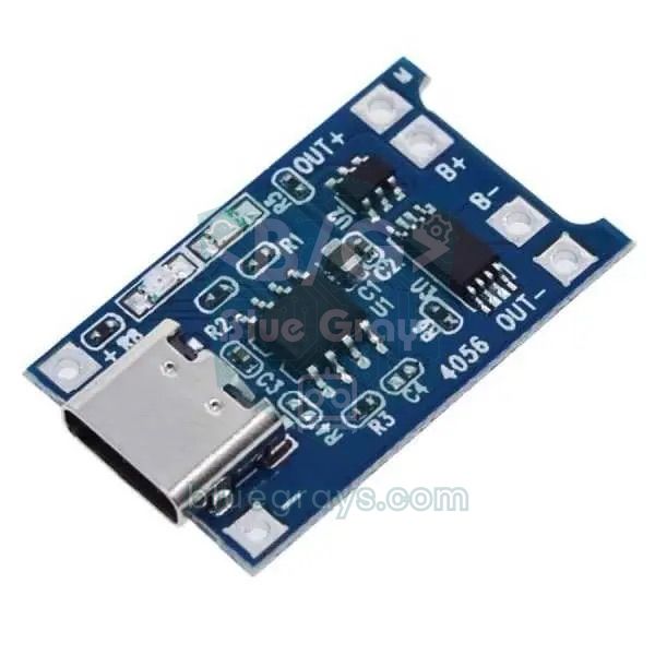
Lithium batteries hold the most energy of anything in the classroom. An 18650 cell is 4.2 V when full, 3.6–3.7 V nominal and usually 2000–3500 mAh; LiPo batteries use the same chemistry in a soft pouch, so they are more vulnerable to crushing and puncturing. The problem is not capacity but how fast that energy can be released: a short circuit, overcharging, over-discharging or mechanical damage can start self-sustaining heating inside the cell. That is why lithium batteries do not appear on desks in the first lessons at all; when there is a real need, such as a battery-powered ESP32 project, the teacher hands them out and counts them back in at the end. We covered the TP4056 module's wiring and its protected version in the TP4056 charging module article and battery power options in the running Arduino on batteries article.
- Never use a swollen battery: A LiPo with a puffed-up pouch or an 18650 that is crushed, dented or has a torn wrapper is taken out of use immediately. Do not puncture, bend or try to flatten it; put it in a non-flammable container (for example a metal box with sand), keep it away from anything flammable and take it to a battery collection point.
- Charge under supervision: Charging with a TP4056 happens only at the teacher's desk, on a non-flammable surface and while someone is in the room. When the room empties, the charging cable comes out; no battery stays on charge overnight or over a weekend.
- Use the right module: Use the protected TP4056 module with output terminals (OUT+ and OUT−); the version with only B+ and B− does not protect against over-discharge or a short on the output. The module usually charges at 1 A, which can be too much for a small LiPo, so check the charge current on the battery's label.
- Polarity and shorts: Check + and − before putting a cell in its holder; a reversed cell heats the module straight away. Never carry a bare cell in a pocket, a bag or a box with metal parts; tape over exposed terminals.
- Storage: Lithium batteries that will not be used for a long time are stored about half charged (around 3.7–3.8 V per cell), somewhere cool and dry, in a closed non-flammable box, with terminals that cannot touch each other.
- Temperature: Do not leave batteries on a sunny windowsill, on a radiator or in a hot car; do not charge them below 0 °C.
- Coin cells: Coin cells such as the CR2032 hold little energy; their main risk is being swallowed by young children. Keep them counted and in their packaging and tell students not to take them home.
Soldering station rules
Breadboard projects in the first term need no soldering; soldering usually starts with modules sold without soldered pin headers, permanent circuits and club work. For lead-free solder the iron tip is typically set to 330–370 °C, and it stays hot for several minutes after being switched off. Most of the visible smoke during soldering comes from the flux inside the solder wire; it can irritate the eyes and airways, so ventilation is always needed. Use lead-free solder wire at school: it removes the risk of contact with lead. Hands are still washed afterwards, because flux residue stays on the fingers. You will find the technique step by step in the how to solder article; this section is only about station rules.
- Location: The soldering corner is set up near a window or fume extractor, away from walkways and on a non-flammable surface. The iron's cable does not hang over the edge of the desk.
- Number of people: One student solders per station, with one observer next to them. The teacher stands where all stations are visible at once; two stations are enough for the first year.
- Stand: When the iron is not in a hand, it is in its stand; it is never laid on the desk or pulled by its cable. Nobody tries to catch a falling iron; let it drop.
- Glasses and clothing: Solder and clipped leads can spit or fly; safety glasses go on, long hair is tied back and loose sleeves are rolled up.
- Fumes: Keep your face out of the fume plume; no soldering without a fume extractor or an open window.
- Holding the part: The part is held with helping hands, a small vice or tape, never with fingers; a fresh joint is not touched for a few seconds.
- Finishing: At the end of the lesson the iron is switched off, unplugged and left in its stand until it is cold; then hands are washed.
Motors and external power: never drive a motor from a pin
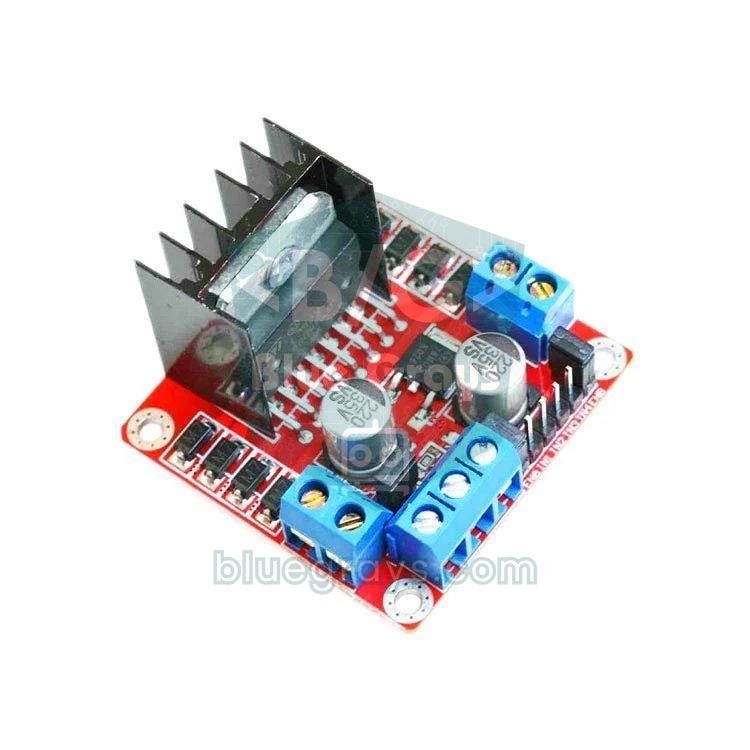
According to the datasheet of the microcontroller on the Arduino Uno, a pin can take at most 40 mA; for continuous use you should stay under 20 mA, and the board's total current has a limit too. That is enough for an LED and far too little for a motor: a small DC motor draws a few hundred milliamps while turning and more when stalled, and its coil produces a reverse voltage when it starts and stops. A motor connected straight to a pin can permanently damage the pin, reset the board or shut down the USB port. The right way is for the pin to give only the command, while a driver (transistor, MOSFET, L298N, L9110S, ULN2003) and a separate power supply carry the current. ESP32 and Raspberry Pi Pico pins work at 3.3 V, and these boards do not drive motors directly either.
| Load | Typical current | Directly from a pin? | Correct connection |
|---|---|---|---|
| 5 mm LED | 10–20 mA | Yes, with a resistor | 220–330 Ω series resistor at 5 V |
| Relay module (5 V, 1 channel) | Coil around 70 mA | Coil no; the module's signal input yes | The transistor and diode on the module drive the coil; low-voltage load only |
| SG90 servo | 100–250 mA idle, over 500 mA when stalled | Signal yes, power no | Signal to the pin; separate 5–6 V supply (4 × AA or 5 V adapter); common GND |
| MG996R servo | Over 2 A when stalled | Signal yes, power no | Separate 5–6 V supply that can deliver at least 3 A; common GND |
| Geared DC motor (TT) | 100–250 mA running, close to 1 A when stalled | No | L298N or L9110S driver, separate battery pack, common GND |
| 28BYJ-48 stepper motor | 200–250 mA | No | ULN2003 driver board, separate 5 V supply, common GND |
- Start with the power off: USB unplugged, battery pack switched off or empty.
- Choose the supply for the load: 5–6 V for an SG90, 6–9 V for a TT motor with an L298N. With an adjustable bench power supply, set the voltage first, start with a low current limit (for example 0.5 A) and raise it step by step if needed.
- Run the motor supply's + only to the driver and the motor; never to the Arduino's 5V pin.
- Connect the supply's GND to the Arduino's GND: without a common GND the driver cannot read the Arduino's signal correctly.
- Compare the wiring with the diagram; your partner checks the polarity too (red +, black −).
- Power the Arduino from USB and upload the code first, then switch on the motor supply. Switch off in reverse order: motor supply first, then USB.
- For the first 30 seconds hold the back of your hand near the driver and motor without touching them; if you feel heat, cut the power and check the wiring again.
We explained how to choose a driver in the DC motor control with L298N and using a MOSFET with Arduino articles. To work out how long a battery pack will run a motor, see the what does mAh mean article. A bench power supply is not essential in the first year; a 4 × AA alkaline pack is enough for small motors and servos, and it delivers less current into a short than a lithium cell. If you do buy an adjustable supply, teach the current limit on day one: a correctly set current limit stops a short circuit before anyone smells burning.
Mains voltage: why mains projects stay out of the classroom
In Europe and many other countries the wall socket supplies 220–240 V AC (in North America 120 V). Either can drive a dangerous current through the body, and a wiring mistake can cause a fire. Hobby projects usually reach the mains in two ways: relay modules and small AC-DC converter modules that turn mains into 5 V. On cheap relay modules the mains side consists of open screw terminals and bare solder joints under the board; at a crowded breadboard desk a finger or a jumper wire touches them easily. We explained how a relay module works and why its mains side needs extra care in the what is a relay module article. AC-DC converters such as the HLK-PM01 belong in the same group: they do not go on a student workbench.
BlueGrays also has advanced projects that switch a 220V bulb with a button or a remote control. In class, build them with the same code but at low voltage: let the relay switch an LED with a resistor, or a small lamp or fan powered from a separate 5–12 V supply. Students learn the relay's click, how its contacts open and close and the logic of the code exactly the same way; you explain the mains part yourself, using a closed, ready-made product. If a student wants to build a mains-powered project at home, your answer should be "under the supervision of a qualified electrician", not "let's try it once in class".
Teacher checklist: before and after class
Copy and print the two lists below and keep them in a folder on your desk. The before-class list takes about 5 minutes, the after-class list 3–4 minutes. In a large class you can hand counting and packing up to student roles, but tick the items about power, batteries, the soldering iron and heat yourself. If you cannot tick an item, postpone that part of the lesson: if the fume extractor is not working, moving soldering to the next lesson is not a change of plan, it is the rule in action.
- Before class: The rules poster, first aid kit, fire extinguisher and the responsible person's phone number are visible.
- Before class: Today's power source is clear: USB only, a battery pack or a bench supply? If batteries are used, they are counted and in their box.
- Before class: The lithium battery box is closed and locked; no battery has been left on charge.
- Before class: No liquids on the desks; extension leads switched off and cables out of the walkways.
- Before class: Safety glasses counted and on the desks; if a laser is used, the wall target is up.
- Before class: If there is soldering, the fume extractor works or the window is open; iron stands, cleaning sponges and lead-free solder are in place.
- Before class: If motors or external power are used, battery packs or the power supply are on the teacher's desk with the current limit set.
- Before class: You have reviewed today's circuit diagram and common sticking points; the red-labelled faulty box is empty and in its place.
- After class: All USB cables unplugged; battery packs switched off and batteries removed.
- After class: The soldering iron is off, unplugged and in its stand until cold; nobody picks it up.
- After class: Lithium batteries counted and back in the locked box; anything missing is searched for before the class leaves.
- After class: Hot, swollen or broken parts are in the faulty box and written in the incident log.
- After class: Desks and floor cleared of lead clippings and small parts.
- After class: Extension leads switched off; fume extractor off or window closed.
- After class: If there was an incident, it has been reported following your school's procedure and noted down.
If something happens: a hot part, smoke, a burn
Most incidents in a lab are small: a regulator gets hot, an LED dies, someone touches the tip of the iron. The way to keep a small incident small is for everyone to know the same first step by heart: cut the power, step back, call the teacher. Medical treatment is outside the scope of this article; for burns and injuries follow your school's first aid procedure and its designated first aider, and keep a copy of that procedure in the checklist folder. The table below only separates who does what; it does not replace first aid steps.
| Incident | What the student does | What the teacher does | Afterwards |
|---|---|---|---|
| Hot part or burning smell | Pulls the USB cable, raises a hand, does not touch the part | Confirms the power is off, waits for the part to cool, checks the circuit against the diagram | Part goes into the faulty box, the cause into the incident log |
| Smoke or a spark | Cuts the power, steps back from the desk | Clears the area around the desk, ventilates the room; if there is a flame, starts the school's fire procedure | The circuit is photographed before taking it apart and the cause is found together |
| Battery getting hot, swelling or hissing | Does not touch it, moves away, tells the teacher | Moves students away, does not carry the battery bare-handed, follows the school's fire procedure | Battery goes to a collection point; charging and storage routine is reviewed |
| Soldering iron burn | Puts the iron in its stand, tells the teacher | Follows the school's first aid procedure, calls the first aider | Soldering corner layout and supervision are reviewed |
| Something in an eye or a laser beam | Does not rub the eye, tells the teacher | Calls the first aider, informs parents according to procedure | The glasses rule and laser target are discussed with the class again |
| A plugged-in mains cable on a desk | Does not touch it, tells the teacher | Unplugs it from the wall and removes the cable from the desk | The mains rule is discussed with the class again |
For the incident log, a page with five columns is enough: date, desk or box number, what happened, the power source used and the action taken. By the end of a term the log tells you which rule needs explaining more often: three incidents of the same kind mean the rule or the lesson routine needs to change. Talk about incidents without blaming the student, by asking "what happened in the circuit?". That conversation is also part of a troubleshooting habit and follows the same logic as the order in the my Arduino project is not working article: power first, then connections, then parts.
Choosing safe values in the app: tools and Troubleshooting
Part of safety is choosing the right value, and showing it with a calculation in class is the easiest way to justify a rule. In the LED resistor tool in BlueGrays, choose 5 V as the supply, red as the colour and 15 mA as the current: the tool calculates 210 Ω and suggests 220 Ω, the next standard value up. Use the Ohm's law tool to show the same idea the other way round: 5 V across 220 Ω is about 23 mA, while 5 V across a 0.1 Ω jumper wire is 50 A on paper. In practice the USB fuse cuts that current off, but a lithium battery has no such fuse. Both tools are free. The Battery life tool is Premium; with a free account it opens as a Sample calculation and shows, with presets such as 18650, LiPo and 9 V, how long a battery can power a load. That calculation teaches students to think "the right battery for the load" instead of "a bigger battery".
The project page also has sections that help with safety. The Required Components list shows which parts and how many, and the Circuit Diagram shows where every wire goes; zooming into the diagram and putting it next to the built circuit is exactly the check in rule 2. In the Let's build it together guided mode, the build step comes with the tip "keep the board's USB cable unplugged while wiring". The If you get stuck section in the Understand the code tab lists common problems in that project as symptom and fix, and is open to everyone in free projects. The Troubleshooting section gives check steps starting with "if your project is not working" in more than 170 projects and is unlocked with Premium. If a part is getting hot, cut the power first and look at these sections afterwards. You can run your first safety lesson with the free LED Blink project: one LED, one resistor and nearly all 10 rules. The full list of free and Premium sections is in the what BlueGrays Premium unlocks article.
Safety rules are not a sheet you hang once and forget; they are a routine repeated in the first and last five minutes of every lesson. In the first week bring the 10 rules, the rule hunt and the checklist; put motors, batteries and the soldering iron on the desks only once that routine is in place. When preparing a lesson, opening the next project in BlueGrays and looking at its circuit diagram and sticking points in advance also tells you which rule to stress that day.
Frequently asked questions
Can 5 V from an Arduino give you an electric shock?
No, 5 V from USB and 3.3 V boards do not push a noticeable current through dry skin. The risk here is not a shock but wires and parts heating up in a short circuit. That is why unplugging USB while rewiring and checking the 5V and GND lines before powering up remain the basic rules.
Should students build 230 V relay projects with Arduino at school?
No, not in student projects. The mains side of a relay module consists of open terminals and bare solder joints that are easy to touch on a workbench. Switching an LED or a small 5–12 V lamp with the same code and the same relay teaches the whole topic without the mains risk.
What should you do with a swollen LiPo battery?
Stop using it immediately; do not puncture, bend or charge it. Keep it in a non-flammable container, such as a metal box with sand, away from flammable materials, and take it to a battery collection point. If it is getting hot or smoking, do not touch it and follow the school's fire procedure.
Can you connect a motor directly to an Arduino pin?
No. An Uno pin can take at most 40 mA and 20 mA is recommended for continuous use, while even a small DC motor draws hundreds of milliamps. A motor is powered through a driver such as an L298N or L9110S and a separate power supply, with the supply's GND connected to the Arduino's GND.
Are soldering fumes harmful, and should schools use lead-free solder?
The visible smoke while soldering comes mostly from flux and can irritate the eyes and airways, so a fume extractor or an open window is needed. Using lead-free solder at school removes the risk of contact with lead. Either way, hands are washed after soldering and there is no food at the soldering station.
Do students need safety glasses in an electronics lab?
Yes when cutting leads, soldering and working on motor projects. Clipped leads and solder can fly, and a reversed electrolytic capacitor can pop open. For lessons with only LEDs and sensors on a breadboard you can set the rule according to your school's lab policy.
Projects to build after reading this
See all projects
LED Blink
The very first hello of electronics: switching a single LED on and off. The Arduino turns the LED on and off at short intervals, so the light blinks quickly. You see in the simplest way how the board

LED Control with a Push Button (Push)
Just like a doorbell: the light stays on as long as you press, and goes off when you let go. The Arduino keeps listening to the button; while it's pressed the LED is on, and the moment you lift your f

Night Light with Ldr
A little night light that turns on by itself when it gets dark and goes off when morning comes. A light sensor measures how bright the room is, and the Arduino switches the LED on when it is dark enou
HC-SR04 Distance Measurement (Serial Display)
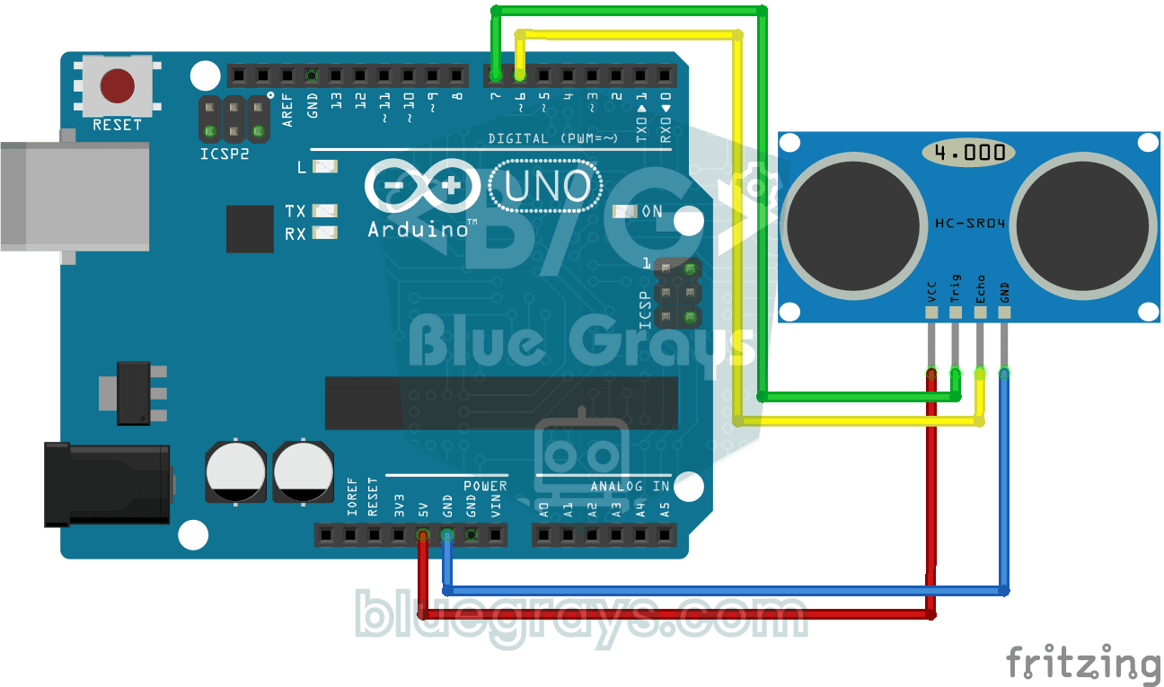
The HC-SR04 sensor works just like a bat finding its way in the dark: it sends out a sound you cannot hear, listens for the echo and measures how far away the object in front of it is. The Arduino wri

LED Blink with ESP32
Teaches basic GPIO output usage with ESP32. We achieve a blinking effect by turning an LED on and off from a digital pin. ESP32 version of the classic blink project on Arduino UNO; the basic blink commands in the Arduino environment are the same, but the ESP32's pin layout and 3.3 V GPIO levels differ from those of the Arduino UNO.
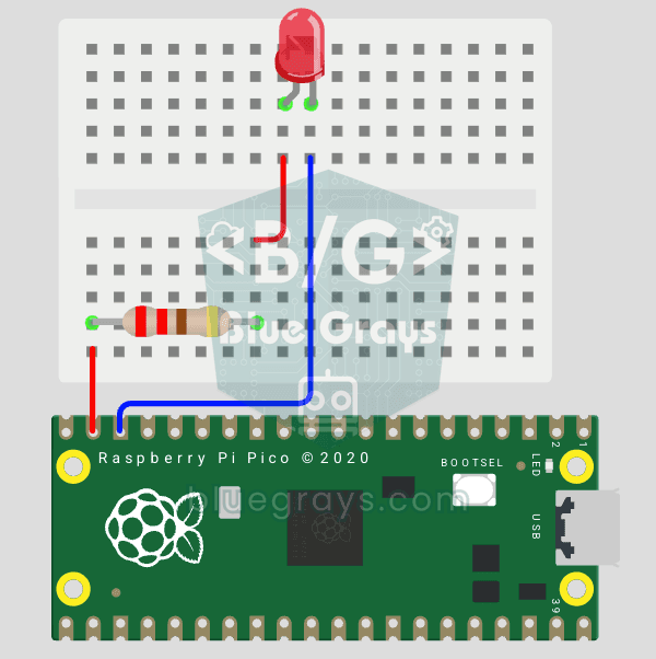
Raspberry Pi Pico: Controlling an External LED (Breadboard)
The next step after Pico’s built-in LED: connecting an external LED to the breadboard and controlling it via the GP14 pin. In this project, you’ll learn how to use any of the Pico’s general-purpose GPIO pins as an output, the LED’s polarity (long leg = anode/+, short leg = cathode/–), and why a current-limiting resistor (220Ω) is required. If you don’t include the resistor, excessive current will flow through the LED and it may burn out. The circuit is very simple: Pico GP14 → 220Ω resistor → LE
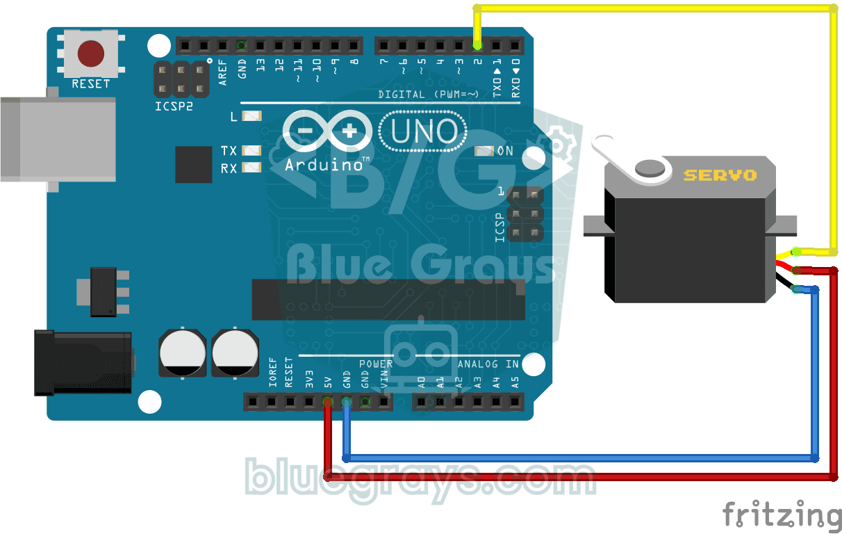
Using a Servo Motor
The arm of a small servo motor turns to three positions in turn: all the way to the start, right to the middle and all the way to the end, waiting two seconds at each stop. The Arduino tells the motor
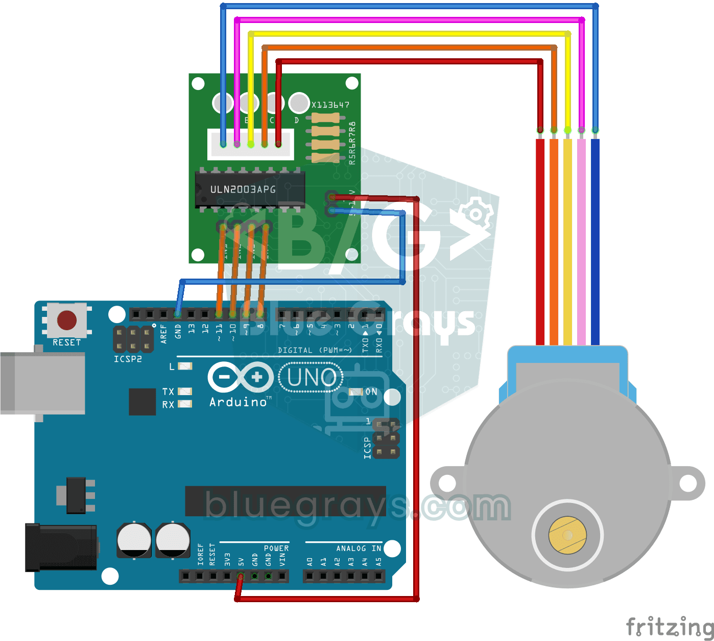
Using a Stepper Motor
A motor that turns step by step, exactly as far as you want, like the hand of a clock. Through a driver board, the Arduino turns a small stepper motor one full turn in one direction, waits a second, t