
Arduino Project Not Working? A 10-Minute Troubleshooting Order
Arduino project not working? Check 6 layers from the outside in: power, upload, wiring, parts, code, sensor. Flow table, test sketch and an 8-point checklist.
If your Arduino project is not working, don't hunt for the fault by pulling wires at random. Work from the outside in: first power (does the board turn on?), then upload (did the code actually reach the board?), then wiring (is GND shared, is each wire on the right pin?), then part orientation and value (is the LED reversed, is the resistor right?), then code (pin numbers and logic) and finally sensor and environment (light, distance, supply voltage). Run one test per layer and change only one thing at a time. Following this order you'll find most faults within 10 minutes, because the most common mistakes sit in the outer layers, and those are the cheapest to check.
This post doesn't list individual error messages; it gives you a troubleshooting method. First you'll see the two rules of the method, then a flow table with the symptom, a 1-minute test and the likely cause for each layer. After that come a short test sketch that splits the circuit into pieces using Blink and the Serial Monitor, 4 multimeter checks (plus LED and Serial Monitor alternatives if you don't own a multimeter), a step-by-step diagnosis of a fault in a free BlueGrays project, a quick-reference table by symptom and an 8-point troubleshooting checklist for the classroom.
The two rules of troubleshooting: outside in, one variable
The logic of going from the outside in is simple: the inner layers depend on the outer ones. If the board has no power, it doesn't matter whether the code is right; if the code never reached the board, fixing the wiring changes nothing. The outer layers are also the quickest to check: looking at the power LED takes 5 seconds and reading the upload message takes 10, but finding a logic error in the code can take minutes. The second rule is the one-variable rule. If you change the wire, the resistor and the threshold in the code all at once, you won't know what fixed it even if the project starts working; and if it doesn't, you may have added a new fault. Make one change, test, write down the result, then move on to the next.
- Write the symptom in one sentence: "When I put my hand over the LDR I expect the LED to turn on, but it never does." "It doesn't work" is not a symptom; once you write what you expected and what happened separately, the layer to check often becomes obvious.
- Unplug USB while wiring: If the board stays powered while you change connections, a wrong touch can cause a short circuit. Make the change, check it visually, then plug back in.
- Swap in a known-good part: Replacing the suspect LED, wire or sensor with one you know works is the strongest test you can do without a meter.
- Take notes: Short notes such as "moved the wire from 7 to 8, no change" stop you from repeating the same test, and they become a ready summary if you ask on a forum or ask your teacher.
- Simplify: If the project is big, take the modules out one by one. First the board alone, then the board plus the output part, then the input part. Seeing which part breaks it shows you where the fault is.
The 10-minute troubleshooting flow table
Read the table below from top to bottom and don't move down to the next layer until the current test passes. Each test takes about a minute, so all six layers are done in 6–10 minutes. For most tests your eyes, the LEDs on the board and the Arduino IDE Serial Monitor are enough; a multimeter speeds things up but isn't required. The "Likely cause" column lists the first places to look when a test fails, roughly in order of how often they happen.
| Layer | Symptom | 1-minute test | Likely cause |
|---|---|---|---|
| 1. Power | Nothing happens, the board LEDs are off or the board gets warm | Is the ON LED lit? Unplug USB and touch the parts: is anything warm? | Charge-only USB cable, loose port, short between 5V and GND, module wired backwards |
| 2. Upload | You changed the code but the board keeps the old behaviour | Did the IDE report that the upload finished, or is there an error line? Are board and port right in the Tools menu? | Wrong board or port, compile error, missing driver, Serial Monitor holding the port |
| 3. Wiring | A part never reacts or only works now and then | Zoom into the diagram and count every wire at both ends; is GND shared with the board? | Row offset on the breadboard, split power rail, D and A pins mixed up, broken jumper |
| 4. Part orientation and value | LED off or very dim, button always reads as pressed | Does the LED's long leg go to the pin? What do the resistor bands say? Is the button rotated 90 degrees? | Reversed LED, 10 kΩ instead of 220 Ω, LDR and resistor swapped, VCC and GND order on a module |
| 5. Code | The board runs but behaves wrongly | Match every pin number in the code to the circuit; print checkpoints to the Serial Monitor | Wrong pin number, missing pinMode, = mixed up with ==, unsuitable threshold or delay |
| 6. Sensor and environment | Values never change, make no sense or jump around | Watch the sensor value in the Serial Monitor and change the conditions (turn off the light, move your hand closer) | Ambient light, sensor out of range, warm-up time, 3.3 V vs 5 V mismatch, long wires and noise |
Layers 1 and 2: power and upload
On an Arduino Uno, two LEDs give you the first clue for these two layers. The ON LED shows the board is powered; if it's off, change the USB cable first, because some cables only charge and don't carry data. If ON is lit but your computer's USB sound cuts out when you plug in, or the LED flickers, there may be a short in the circuit: unplug USB, trace the 5V and GND lines and look for a module plugged in backwards or a wire bridging the two rails. A part that gets hot is always a serious sign; don't power the board again until you remove it. If you use a motor, servo or relay, USB may not deliver enough current; in that case the symptom is usually not "nothing works" but random resets or jitter. For battery and adapter options, see running an Arduino on batteries.
In the upload layer you're answering a single question: is the code on the board the code you see on the screen? When an upload finishes, the Arduino IDE says so in the output area at the bottom; if there are red lines, the code never reached the board and it keeps running its old program. This is sneaky, because you'll think your fix didn't work. For avrdude, port and driver errors, Arduino code not uploading explains each message, and if you're stuck at compile time, see compile errors. There's also a simple proof test: change a delay in the code from 100 to 1000 and upload. If the LED's rhythm doesn't change, the problem is in the upload layer. Some ESP32 boards need the BOOT button held during upload; on a Raspberry Pi Pico, check that the MicroPython interpreter is selected in the bottom right corner of Thonny.
Layer 3: wiring, GND and pins
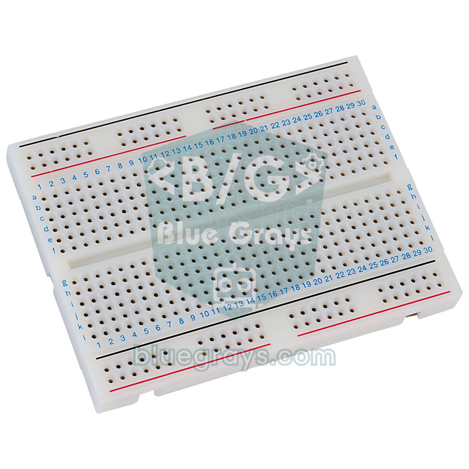
With the board powered and the code uploaded, it's the wires' turn. The two most common mistakes are a forgotten common GND and a misread breadboard. Even if a sensor or module has its own supply, its GND must connect to the Arduino's GND, otherwise the signal voltage has no reference. On a breadboard the centre channel separates the two halves, and on long breadboards the power rails along the edges may be split in the middle; feeding 5V into one half of a rail and assuming it powers a part on the other half is a very common mistake. The best method for this layer is a one-to-one comparison with the diagram: count every wire, both ends, and point to its match on the diagram with your finger. Digital 2 mixed up with analog A2, 5V confused with VIN, or a wire one row off will show up straight away. If the schematic symbols look unfamiliar, how to read a circuit diagram walks you through moving it onto a breadboard.
Layer 4: part orientation and value
If the wiring is right but a part still doesn't respond, look at the part itself. The LED's long leg (anode) should go through the resistor to the pin and the short leg (cathode) to GND; a reversed LED usually isn't damaged, it just stays dark. Resistors are the parts that get mixed up most: 220 Ω has red-red-brown bands, 10 kΩ brown-black-orange. Put 10 kΩ next to an LED and it glows so faintly you won't notice; put 220 Ω next to an LDR or a button and the readings stop making sense. You can read the bands with the resistor colour code calculator and find the right value for an LED with the LED resistor calculator. A four-leg push button rotated 90 degrees will read as always pressed or never pressed. On modules the order of VCC, GND and signal varies by manufacturer, so read the pin labels on the board itself, not from a picture online. Three-leg parts such as transistors and voltage regulators also have different pin orders depending on the model.
Layer 5: code (pin numbers and logic)
If the hardware is sound, check whether the code says the same thing as the circuit. The first check is pin numbers: if the LED is physically on 8 but the code says digitalWrite(9, HIGH), everything looks perfect and nothing happens. The second check is pinMode: if pinMode(pin, OUTPUT) is missing from setup(), digitalWrite(pin, HIGH) doesn't make the pin an output, it only enables the internal pull-up resistor, and the LED glows very dimly. Apart from the resistor, this is the most common cause of a "dim LED". The third check is logic: writing if (value = 100) doesn't compare anything, it assigns 100 to the variable and the condition is always true; the correct form is ==. Thresholds and delays belong to this layer too: a threshold that doesn't suit your surroundings means nothing ever triggers, even with a perfectly working sensor. In projects that use libraries, also check that the right library is installed; details are in installing Arduino libraries.
Layer 6: sensor and environment
The last layer covers outside conditions that spoil the result even when the circuit and code are right. An LDR's value depends on the room light; a threshold that works by the window in daylight may fail under a lamp in the evening. An HC-SR04 gets no echo from soft surfaces such as fabric and can't measure closer than 2 cm. MQ series gas sensors need a few minutes to warm up before measuring. A DHT11 returns errors if you read it more often than once per second. The pins on the ESP32 and the Raspberry Pi Pico run at 3.3 V; connecting a sensor with a 5 V output directly can give wrong readings and can damage the pin. Long wires, noise from motors and floating inputs also make values jump. The best tool in this layer is the Serial Monitor: watch the raw sensor value and change the conditions on purpose. If an I2C display or sensor doesn't respond at all, the scanner sketch in what is I2C shows its address.
Divide and conquer: check the board with Blink, the steps with the Serial Monitor
The fastest way through the layers is to split the circuit and the code into pieces. The first piece is the board itself: with nothing connected, upload code that blinks the on-board L LED. If L blinks, power, upload and board are fine, and from now on you look for the problem outside the board. The second piece is the output: blink the external LED in the same code. The third piece is the input: print the sensor value to the Serial Monitor. The sketch below does all three and prints a numbered checkpoint to the Serial Monitor at each step. Connect the external LED to pin 9 through a 220 Ω resistor and the signal of the analog sensor you're testing to A0, and set the Serial Monitor to 9600 baud.
1const int LED_PIN = 9;       // Harici LED pini / External LED pin
2const int SENSOR_PIN = A0;   // Analog sensör pini / Analog sensor pin
3
4void setup() {
5  Serial.begin(9600);                  // Seri monitör de 9600 olmalı / Serial Monitor must be 9600 too
6  pinMode(LED_BUILTIN, OUTPUT);        // Karttaki L ışığı / On-board L LED
7  pinMode(LED_PIN, OUTPUT);            // Harici LED çıkış / External LED as output
8  Serial.println("1) setup bitti");    // Kontrol noktası 1 / Checkpoint 1
9}
10
11void loop() {
12  digitalWrite(LED_BUILTIN, HIGH);     // Kart canlı mı? / Is the board alive?
13  digitalWrite(LED_PIN, HIGH);         // Harici LED açık / External LED on
14  Serial.println("2) LED acik");       // Kontrol noktası 2 / Checkpoint 2
15  delay(500);
16
17  digitalWrite(LED_BUILTIN, LOW);
18  digitalWrite(LED_PIN, LOW);          // Harici LED kapalı / External LED off
19  Serial.println("3) LED kapali");     // Kontrol noktası 3 / Checkpoint 3
20  delay(500);
21
22  int value = analogRead(SENSOR_PIN);  // 0-1023 arası okuma / Reading from 0 to 1023
23  Serial.print("4) A0 = ");
24  Serial.println(value);               // Sensör değeri / Sensor value
25}| What you see in the Serial Monitor and on the board | What it means | Layer to check |
|---|---|---|
| Serial Monitor empty and L not blinking | The code isn't running or never reached the board | 1. Power, 2. Upload |
| Garbage characters scroll past | The Serial Monitor speed doesn't match Serial.begin(9600) | 5. Code (baud setting) |
| "1) setup bitti" reappears every so often | The board is resetting itself, usually because the supply isn't enough | 1. Power |
| 2 and 3 alternate, L blinks but the external LED stays dark | Code and board are fine; the external LED's path is broken | 3. Wiring, 4. Part orientation and value |
| A0 always near 0 or always near 1023 | The signal line goes to GND or 5V, the sensor isn't powered or the divider resistor is missing | 3. Wiring, 4. Part value |
| A0 jumps randomly with nothing connected | The pin is floating; that's normal and should stop once the sensor is connected | 3. Wiring |
The real power of this sketch is its checkpoints. Use the same method in your own project: add a short Serial.println() at the end of setup() and after every important step in loop(), for example "button pressed" or "threshold passed". The last message that appears in the Serial Monitor tells you where the program got stuck. To find out why a condition never fires, print the value you compare right before the condition; if "value < 50" is never true, you'll see right there that the value never drops below 50. In bigger projects, use the same logic: comment out part of the code temporarily and test the pieces one by one. For Serial Monitor settings such as baud rate, line ending and the plotter, see using the Arduino Serial Monitor.
4 multimeter checks (or LED and Serial Monitor without one)
A multimeter turns troubleshooting from guessing into measuring, and just four measurements cover most Arduino faults. Before measuring, set the meter to the right mode: DC V for voltage, beep (continuity) for checking wires and rows, Ω for resistance. Always do the continuity and resistance checks with USB unplugged. If you don't have a multimeter, the methods in the last column give a rougher but sufficient answer to the same question. The meter's ranges and which sockets the probes go into are explained with pictures in how to use a multimeter.
| Check | Meter setting and probes | Expected | Without a multimeter |
|---|---|---|---|
| Supply voltage | DC V; black probe on GND, red probe on the 5V pin (board on USB) | About 4.7–5.1 V; about 3.3 V on the 3.3V pin | Look at the ON LED and upload Blink; if L blinks steadily, the supply is fine |
| Wire and breadboard row | Beep mode, USB unplugged; touch both ends of the wire or two holes in the same row | A beep; no beep means a broken wire or a different row | Swap the suspect wire for a known-good one; connect an LED and 220 Ω resistor between 5V and GND through that wire |
| Resistor value | Ω range; take the resistor out of the circuit and touch both legs | About 209–231 Ω for 220 Ω (5 percent tolerance) | Read the colour bands and confirm with the colour code calculator |
| Signal voltage | DC V; black probe on GND, red probe on the output pin or the sensor's signal line | About 5 V when the output is HIGH, 0 V when LOW; a light-dependent value in the LDR divider | Watch the analogRead value in the Serial Monitor (5 V is about 1023, 0 V about 0); connect an LED to the output pin |
Worked example: the LED won't turn on in the Night Light with LDR project
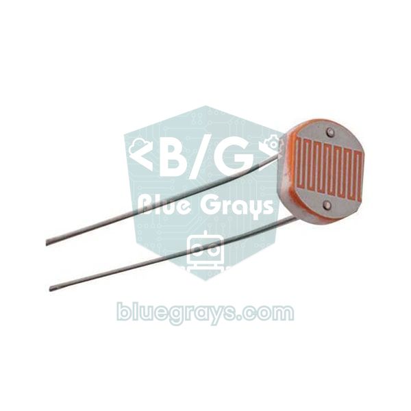
Let's try the method on a free BlueGrays project: Night Light with Ldr. In the circuit, one end of the LDR goes to 5V and the other to A0; a 10 kΩ resistor sits between A0 and GND, and the two form a voltage divider. The LED connects to pin 13 through a 330 Ω resistor. The code reads A0 and, if the value is below 50, treats the room as dark and turns the LED on. The symptom: "I cover the LDR with my hand and the LED never turns on." Instead of swapping wires at random, let's go through the layers in order.
- Power: The ON LED is lit and nothing is warm. Move on.
- Upload: The upload finished without errors. To be sure, temporarily change the 50 in the code to 2000 and upload; since analogRead returns at most 1023, the condition is always true and the LED should stay on.
- Wiring and the L LED: Pin 13 is also wired to the on-board L LED. If L lights with the 2000 threshold but the external LED doesn't, the code is running and the problem is in the LED's path. Does the LED's long leg go to 13 through 330 Ω and its short leg to GND?
- Part orientation and value: The LED isn't reversed, but if there's a 10 kΩ next to it instead of 330 Ω, it glows too faintly to notice. Tell the two resistors apart by their colours.
- Code and sensor: If the external LED lights with the 2000 threshold, set it back to 50. Now, to see the real values, upload the code of the Measuring Light Intensity with an LDR project to the same circuit; it uses the same LDR wiring and prints A0 to the Serial Monitor every half second.
- Read the values: Say you see around 600 uncovered and around 120 when you cover it with your hand. The value never drops below 50, so the LED never turns on. Go back to the night light code and raise the threshold to somewhere between 200 and 300.
- Spot reversed behaviour: If the value rises instead of falling when you cover it, the LDR and the 10 kΩ have swapped places. If the value jumps randomly while your hand is still, the A0 wire isn't seated in the row where the LDR and resistor meet.
What found the fault in this example wasn't new knowledge but the order: first we proved the LED itself could light, then we looked at what the sensor actually reads. In the app, the If you get stuck section of this project's Understand the code tab already has five of these symptoms as symptom and solution pairs: the external LED never lighting in the dark, the LED lighting in the light and turning off in the dark, not lighting even when covered by hand, staying on or flickering, and an upload error. The project's Troubleshooting section gives a general 10-step checklist that starts at power and goes through upload, pin numbers, breadboard, jumper wires, GND, the LED and the resistor. As you may have noticed, that order is almost the same as the layers at the start of this post.
Help in the app: where to look when a project doesn't work
- Troubleshooting: An ordered checklist on the project page that starts with "If your project is not working, check the steps below." It's available on more than 170 projects and opens with Premium; on free projects this section is also shown with Premium. If you have no idea what's broken, this is the place to go through from start to finish.
- Understand the code > If you get stuck: Symptom and solution pairs specific to that project's code and circuit. Open to everyone on free projects, with Premium on Premium projects. If you can write your symptom in one sentence, look here first. The whole section is covered in the Understand the code post.
- Go back to the Let's build it together steps: In the guided mode, return to 2. Build the circuit and rebuild the circuit from scratch with the board's USB cable unplugged; at 3. Upload the code, double-check the board and port in the Arduino IDE Tools menu. The mode remembers the step you were on. How it works is explained in your first Arduino project.
- Zoom into the circuit diagram: Pinch to zoom into the Circuit Diagram and compare your wiring connection by connection; if you like, save it with Save to Gallery and mark the wires you've checked. This catches most layer-3 faults.
- Ask the right question on the forum: If you've tried all of this and it still doesn't work, start a topic in the Question category in Learn › Forum. Write the board, the full code, the connections, the expected and actual behaviour and which layers you've checked, and add a clear photo of the circuit. How to write it is in asking on the forum.
Quick reference by symptom
| Symptom | Layer to check first | First test | Related post |
|---|---|---|---|
| Nothing happens, the ON LED is off too | 1. Power | Try another USB cable and port; look for a short between 5V and GND | Running an Arduino on batteries |
| Code won't upload, avrdude or port error | 2. Upload | Board and port in the Tools menu; a cable that carries data | Arduino code not uploading |
| Red error lines when compiling | 5. Code | Read the first error line and go to that line number | Compile errors |
| LED lights but very dimly | 4. Part value, 5. Code | Resistor colours; is there a pinMode(…, OUTPUT) in setup()? | What is an LED |
| Sensor always 0 or always 1023 | 3. Wiring | The sensor's VCC and GND, the row of the signal wire, the divider resistor | Voltage divider |
| Button seems to press itself | 3. Wiring | Is there a pull-down resistor, or is INPUT_PULLUP used? | How to wire a button |
| Servo jitters | 1. Power | Power the servo from a separate 5 V supply and join the GNDs | What is a servo motor |
| Board resets at random | 1. Power | Remove the motor or relay and test; does the setup message repeat in the Serial Monitor? | Arduino keeps resetting, ESP32 brownout |
| Garbage characters in the Serial Monitor | 5. Code | Match the Serial Monitor speed to the Serial.begin() value | Using the Serial Monitor |
For teachers: an 8-point troubleshooting checklist
Say you have a class of 24 with 8 groups building circuits at the same time, and in the first 15 minutes six groups raise their hands saying "it doesn't work". Put the checklist below on every group's table and set the rule from the start: before raising a hand, go through the card from top to bottom and write on the back which point you got stuck on and what you changed. This frees up your time and builds problem-solving habits in your students; the troubleshooting notes are also evidence of process you can use in assessment. For group organisation in a large class see teaching Arduino to a large class, and for grading the process see the assessment rubric.
- Symptom: What did we expect, and what happens? Write it in one sentence.
- Power: Is the ON LED lit? Unplug USB: is any part warm?
- Upload: Did the upload finish without errors? Are board and port right in the Tools menu?
- Board: After uploading Blink, does the on-board L LED blink?
- Wiring: Zoom into the diagram and count every wire at both ends. Is GND shared, are the wires on the right pin and the right row?
- Part: Does the LED's long leg go to the pin? Do the resistor bands match the value in the parts list? Are VCC and GND right on the module?
- Code: Do the pin numbers in the code match the circuit? When you print checkpoints to the Serial Monitor, which one appears last?
- Sensor and next step: Does the sensor value in the Serial Monitor make sense, and does it change when the conditions change? If it's still not solved, check If you get stuck and Troubleshooting, then call the teacher. Change one thing at a time and take notes.
Troubleshooting is a skill, and it gets faster with every fault: a search that takes 20 minutes on your first project drops to 3 minutes by your fifth, because you start to guess the layer from the symptom. Next time a project doesn't work, open this order before you pull any wires and work from top to bottom. Small projects like the night light in this post are ideal for practice; in the BlueGrays app, each of the 60 free projects comes with its circuit diagram, code and Understand the code section, so on your next fault you'll already know where to look.
Frequently asked questions
Why is my Arduino project not working?
The most common causes, in order, are power problems, code that never reached the board, a missing common GND or a wire one row off on the breadboard, a reversed LED or wrong resistor value, and a wrong pin number in the code. Check them in that order, changing one thing at a time, and you'll usually find the fault within 10 minutes.
How do I know if my Arduino is broken?
Disconnect everything, connect the board with only the USB cable and upload the Blink example. If the ON LED is lit, the upload finishes without errors and the L LED blinks, the board is most likely fine and the problem is in the circuit or the rest of the code. If the board doesn't show up as a port at all, first try another data cable and USB port.
Why does my Arduino code upload but not work?
First check that the upload really finished; if there's an error line, the board runs the old code. If the upload is fine, match the pin numbers in the code to the circuit, check that setup() contains the pinMode lines and add a Serial.println() at the end of setup() to see in the Serial Monitor whether the program gets that far.
Why does the Serial Monitor show garbage characters?
The Serial Monitor speed doesn't match the Serial.begin() value in your code. If the code says 9600, set the speed in the bottom right of the Serial Monitor to 9600 as well. On an ESP32 the boot messages are sent at 115200 baud, so a few garbled lines at 9600 are normal.
How can I test an Arduino circuit without a multimeter?
The ON and L LEDs on the board tell you about the supply and the board, and analogRead values printed to the Serial Monitor show the sensor signal. Swapping a suspect wire or LED for a known-good part replaces a continuity test. You can read a resistor's value from its colour bands and confirm it with the colour code calculator.
Why does my Arduino analog sensor always read 0 or 1023?
Always 0 usually means the signal line goes to GND or the sensor isn't powered; always 1023 means the signal line is tied straight to 5V or the divider resistor is missing. Check the sensor's VCC and GND, that the signal wire is in the right row, and for parts like an LDR that the 10 kΩ resistor is in place.
Projects to build after reading this
See all projects
Night Light with Ldr
A little night light that turns on by itself when it gets dark and goes off when morning comes. A light sensor measures how bright the room is, and the Arduino switches the LED on when it is dark enou

Measuring Light Intensity with an LDR
Want to see how bright your room is as a number? The LDR, a small part that reacts to light, measures the light around it, and the Arduino writes the value to your computer screen every half second. C

LED Blink
The very first hello of electronics: switching a single LED on and off. The Arduino turns the LED on and off at short intervals, so the light blinks quickly. You see in the simplest way how the board

LED Control with a Push Button (Push)
Just like a doorbell: the light stays on as long as you press, and goes off when you let go. The Arduino keeps listening to the button; while it's pressed the LED is on, and the moment you lift your f

Toggle an LED with a Button (On/Off)
Press the button once and the light comes on, press it again and it goes off, just like the light switch in your room. The Arduino notices every press and flips the LED to the opposite state, waiting
HC-SR04 Distance Measurement (Serial Display)
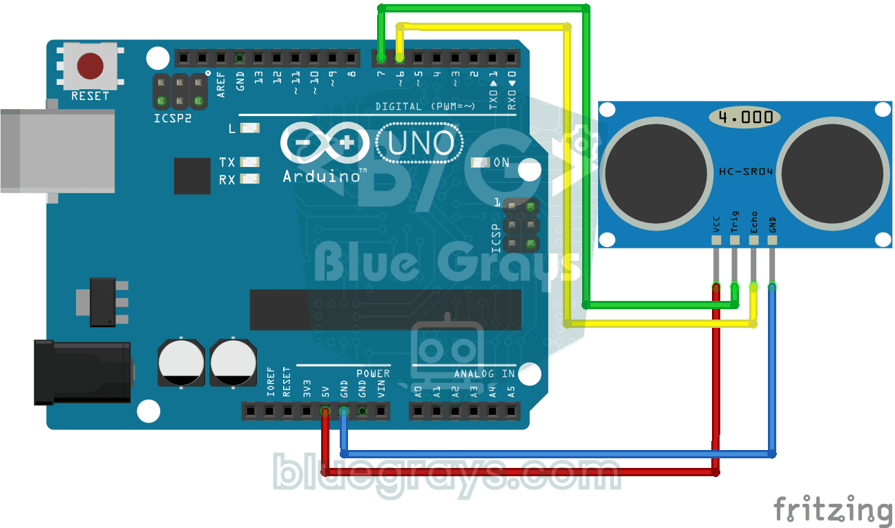
The HC-SR04 sensor works just like a bat finding its way in the dark: it sends out a sound you cannot hear, listens for the echo and measures how far away the object in front of it is. The Arduino wri
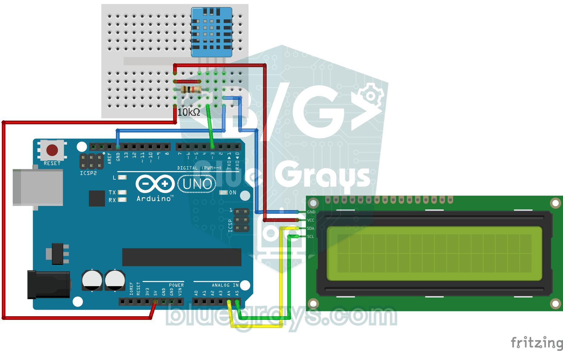
Temperature and Humidity with DHT11
How warm is your room, and is the air humid or dry? The DHT11 sensor measures temperature and humidity, and the Arduino writes the values on a two-line LCD screen, refreshing every couple of seconds.
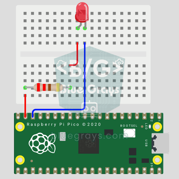
Raspberry Pi Pico: Controlling an External LED (Breadboard)
The next step after Pico’s built-in LED: connecting an external LED to the breadboard and controlling it via the GP14 pin. In this project, you’ll learn how to use any of the Pico’s general-purpose GPIO pins as an output, the LED’s polarity (long leg = anode/+, short leg = cathode/–), and why a current-limiting resistor (220Ω) is required. If you don’t include the resistor, excessive current will flow through the LED and it may burn out. The circuit is very simple: Pico GP14 → 220Ω resistor → LE