
Breadboard Power Supply Module MB102: 5V/3.3V, Current Limits
How to use the MB102 breadboard power supply module: 6.5–12 V input, 5 V and 3.3 V jumpers, the real current limit, AMS1117 heat, servo trouble and common GND.
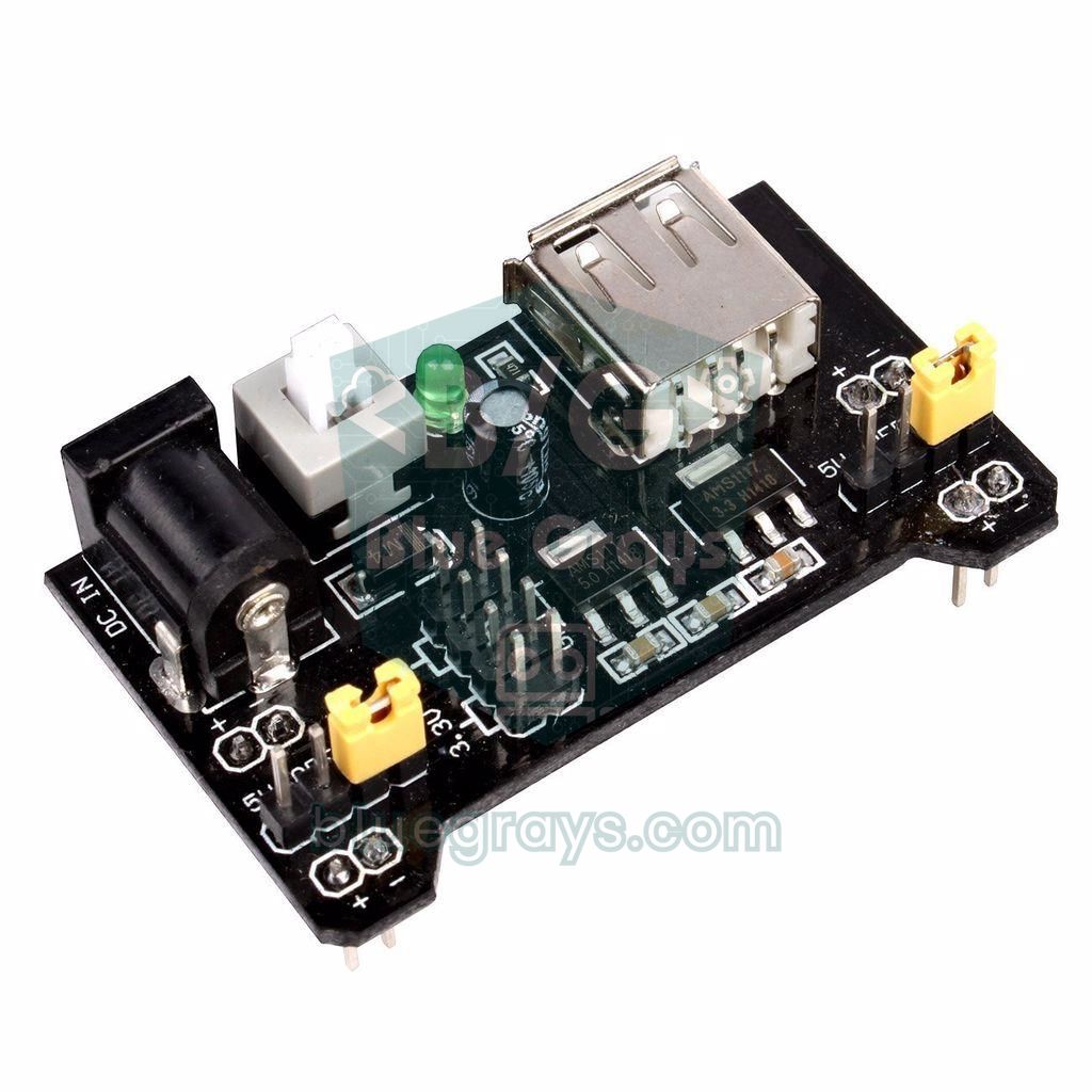
A breadboard power supply module (most commonly the MB102) is a small board that regulates the voltage from a DC adapter or USB and distributes it as 5 V and 3.3 V to the breadboard's power rails. It plugs straight into one end of the breadboard, feeds the positive and negative rails on each side separately and carries jumpers that let you choose 5 V or 3.3 V for each rail. That way you can power sensors, displays and chips without straining the Arduino's own regulator, and use 3.3 V and 5 V parts together on the same breadboard.
But this little board has a much lower current limit than people assume. In this post you'll learn, with calculations, the MB102's parts, how to choose the right adapter, the jumper settings, how many milliamps the board can really deliver and why the AMS1117 regulator gets hot. Then you'll see why servos and motors don't work with this module, the USB input, plugging it into the breadboard the right way round, the common GND with the Arduino and the most common mistakes.
What is a breadboard power supply module and how does it work?
The MB102 board carries two linear regulators: the AMS1117-5.0 drops the input voltage to 5 V and the AMS1117-3.3 to 3.3 V. On most boards the 3.3 V regulator is fed from the 5 V output, so the current you draw from the 3.3 V rail also passes through the 5 V regulator first. On the input there's a diode against reverse connection, an on/off switch and an LED that shows the power is on. The two rows of pins underneath the board sit in the positive and negative rails at both edges of the breadboard.
| Parameter | Value |
|---|---|
| Input (DC jack) | 6.5–12 V DC, 5.5 × 2.1 mm jack, centre positive |
| Input (USB) | 5 V, USB-A socket; the regulator is bypassed and 5 V goes straight to the rail |
| Outputs | 5 V and 3.3 V; selected separately for each side with a jumper |
| Regulators | AMS1117-5.0 and AMS1117-3.3 (SOT-223 package, no heatsink) |
| Current on paper | 1 A for the AMS1117; sellers usually list the module as "less than 700 mA" |
| Realistic continuous current | 200–500 mA depending on input voltage (see the heat calculation below) |
| Extra output pins | 5 V, 3.3 V and GND pin headers on top of the board |
| Protection | Reverse polarity diode on the input; no short-circuit fuse |
Which adapter should I choose? What the 6.5–12 V input means
For a linear regulator to work, its input has to be a certain amount higher than its output; this difference is called the dropout voltage, and on the AMS1117 it's around 1.1–1.3 V depending on the load current. The protection diode on the input takes a few tenths of a volt as well. That's why you need at least 6.5 V on the input for the 5 V output to really be 5 V. If you connect a 5 V adapter, you'll see 3.5–4 V on the output and the Arduino, display or sensors will behave erratically. At the top end the problem is heat: the higher the input voltage, the more power the regulator burns off as heat.
| Adapter | Result | Recommendation |
|---|---|---|
| 5 V adapter (on the DC jack) | Output stays around 3.5–4 V | Don't use it; connect 5 V sources through the USB input |
| 7–7.5 V | Stable 5 V, least heating | Best choice |
| 9 V adapter | Stable 5 V, moderate heating | Good for light loads (under 300 mA) |
| 12 V adapter | Stable 5 V but the regulator gets very hot | Only for 150–200 mA loads |
| 9 V battery | Works, but a capacity of 300–500 mAh runs out quickly | Not recommended except for short tests |
Setting the 5 V and 3.3 V jumpers
At each end of the board there's a three-pin jumper header; each one controls the power rail on one side of the breadboard. Put the jumper on the side marked "5V" and that rail gets 5 V; put it on "3.3V" and it gets 3.3 V; remove the jumper completely and that rail isn't powered. This lets you set one side for a 5 V LCD and the Arduino, and the other for a 3.3 V nRF24L01 or sensor. The negative (GND) rails on both sides are always common.
| Left jumper | Right jumper | Left rail | Right rail | Example use |
|---|---|---|---|---|
| 5V | 5V | 5 V | 5 V | 5 V parts like the Arduino, LCD, HC-SR04 |
| 3.3V | 3.3V | 3.3 V | 3.3 V | 3.3 V sensors with an ESP32 or Pico |
| 5V | 3.3V | 5 V | 3.3 V | Mixed circuit: 5 V LCD on one side, 3.3 V module on the other |
| Removed | 5V | Unpowered | 5 V | Temporarily switching one side off |
The real current limit: why even 700 mA is optimistic
The AMS1117 datasheet says 1 A, and sellers say "less than 700 mA" for the module. But those figures assume the regulator is well cooled. A linear regulator burns off the difference between input and output voltage as heat: P = (Vin − Vout) × I. On the MB102 the regulator is soldered to a small copper area on the board with no heatsink. A SOT-223 package like that can dissipate about 1 W continuously; beyond that it overheats, enters thermal protection and cuts or drops its output.
| Input voltage | Heat at 100 mA | Heat at 300 mA | Heat at 500 mA | Verdict |
|---|---|---|---|---|
| 7 V | 0.2 W | 0.6 W | 1.0 W | Usable up to 500 mA, at the limit |
| 9 V | 0.4 W | 1.2 W | 2.0 W | Overheats above 300 mA |
| 12 V | 0.7 W | 2.1 W | 3.5 W | Goes into thermal protection above 200 mA |
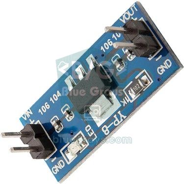
The 3.3 V side is calculated separately: because the 3.3 V regulator is fed from 5 V, it produces (5 − 3.3) × I of heat; at 300 mA that's 0.5 W. On top of that, those 300 mA are added to the 5 V regulator's load as well. In short, the MB102 is ideal for circuits of a few hundred milliamps, such as LEDs, sensors, an LCD and an Arduino Nano. For more, move to a switching regulator such as the LM2596 step-down converter; regulators like that convert the voltage difference efficiently into current instead of heat.
Current budget: how much does your circuit draw?
Before choosing the module, roughly add up the total current of the parts in your circuit. The values below are typical averages; motorised and wireless parts have much higher short peaks. If the total continuous current goes above 300 mA or the peaks above 500 mA, the MB102 alone isn't enough.
| Part | Typical current | Note |
|---|---|---|
| Arduino Uno / Nano | 30–50 mA | Including the on-board LEDs and USB chip |
| ESP32 development board | 80–250 mA | Peaks of 400–500 mA during Wi-Fi transmission |
| 16x2 LCD (backlight on) | 20–30 mA | Together with the I2C backpack |
| 0.96 inch OLED | 10–25 mA | Depends on how many pixels are lit |
| Red LED (with 220 Ω) | ~14 mA | Per LED |
| WS2812B LED | Up to ~60 mA | Per LED at full white; 10 LEDs make 600 mA |
| SG90 servo | ~10 mA idle, 100–250 mA moving | Up to 650 mA under strain |
| Relay module (1 channel) | 70–90 mA | While the coil is energised |
| HC-SR04 | ~15 mA | During a measurement |
Why isn't it enough for servos and motors?
The moment an SG90 servo starts moving it briefly draws a few hundred milliamps, and up to 650 mA when it's straining; on large servos like the MG996R this goes beyond 2 A. DC motors and stepper motors also demand high current at start-up. That sudden current hits the regulator's limit and the 5 V rail drops below 4 V for a moment. The voltage of an Arduino fed from the same rail drops too and the board resets itself; the servo jitters and garbage characters appear on the LCD. Noise from the motors' brushes also ruins sensitive sensor readings.
- Power servos and motors from a separate supply: a 5 V adapter that can deliver at least 2 A, a buck converter like the LM2596 or 4 AA batteries are good choices.
- Join the GNDs: even with a separate supply, connect the motor supply's GND to the Arduino's GND; otherwise the signal has no reference.
- Add a capacitor on the servo supply: a 470–1000 µF electrolytic capacitor across the servo's power leads smooths out the sudden current spikes.
- Use the MB102 for the logic side only: let the Arduino, sensors and display run from the MB102 and the motors from their own supply.
If you want to see this dip for yourself, try the code below. The Arduino Uno can measure its own supply voltage by comparing its internal 1.1 V reference against the supply; no external wiring is needed. Power the Arduino and the servo from the MB102's 5 V rail and watch the minimum voltage in the Serial Monitor while the servo moves:
1// Arduino kendi besleme gerilimini ölçer, servo hareket ederken düşüşü yakalar
2// The Arduino measures its own supply voltage and catches the dip while a servo moves
3// Arduino 5V ve GND -> MB102 5 V hattı / Arduino 5V and GND -> MB102 5 V rail; servo sinyali / servo signal -> D9
4#include <Servo.h>
5
6Servo servo;
7long minVcc = 99999;
8
9long readVcc() {
10  // Dahili 1,1 V referansını AVcc'ye göre ölç / measure the internal 1.1 V reference against AVcc
11  ADMUX = _BV(REFS0) | _BV(MUX3) | _BV(MUX2) | _BV(MUX1);
12  delay(2);                                // referansın oturmasını bekle / let the reference settle
13  ADCSRA |= _BV(ADSC);                     // dönüşümü başlat / start the conversion
14  while (bit_is_set(ADCSRA, ADSC));        // bitmesini bekle / wait until done
15  long result = ADCL;
16  result |= ADCH << 8;
17  return 1125300L / result;                // 1,1 V x 1023 x 1000 / sonuç = mV / result in mV
18}
19
20void setup() {
21  Serial.begin(9600);
22  servo.attach(9);
23}
24
25void loop() {
26  for (int angle = 0; angle <= 180; angle += 90) {
27    servo.write(angle);
28    unsigned long start = millis();
29    while (millis() - start < 600) {       // hareket boyunca ölç / measure during the move
30      long vcc = readVcc();
31      if (vcc < minVcc) minVcc = vcc;
32    }
33    Serial.print("Aci / Angle: ");
34    Serial.print(angle);
35    Serial.print("  Vcc: ");
36    Serial.print(readVcc());
37    Serial.print(" mV  en dusuk / minimum: ");
38    Serial.print(minVcc);
39    Serial.println(" mV");
40  }
41}
The result can be off by ±10% depending on the actual value of the internal reference; for a more accurate reading, measure the 5 V rail once with a multimeter and adjust the 1125300 constant accordingly. If the minimum drops below 4.5 V with the servo connected, or the board resets, it's time to move the servo to a separate supply.
The USB input: both power in and power out
The USB-A socket on the MB102 can be used in two ways. When you power the board from the DC jack, the socket becomes a 5 V output and can power a small USB device. When you power it with a USB A-to-A cable or a power bank, the socket becomes an input: in that case the incoming 5 V bypasses the 5 V regulator and goes straight to the rail, while the 3.3 V regulator keeps working. A computer's USB port usually supplies 500 mA (900 mA on USB 3), and the only short-circuit protection is the port's current limit. If you use a power bank, remember that many models switch themselves off at low current.
Plugging it into the breadboard the right way round
The MB102 is designed for the end of standard 830-point breadboards: the pins underneath sit in the two power rails (positive and negative) on each side. There are + and − markings on the bottom or top of the board; make sure they line up with the red (positive) and blue (negative) lines on the breadboard. On some breadboards the coloured lines are printed the wrong way round or missing altogether; if you plug the module in backwards the positive rail becomes GND, the negative rail becomes 5 V and everything in your circuit is reverse powered. On long breadboards the power rails may be split in the middle; if parts at the far end don't work, check the continuity of the rails.
- Set the module's switch to off and set the jumpers to the voltage you want.
- Press the module into the end of the breadboard so that the + and − markings line up with the breadboard's red and blue rails.
- Connect the adapter to the DC jack and switch on; the LED should light up.
- Measure both rails with a multimeter; if the values are right, switch off and start building your circuit.
- When the circuit is ready, check the connections, especially GND, once more before switching on.
Common GND with the Arduino and powering the Arduino
There are two right ways to use the MB102 with an Arduino. Option one: the Arduino runs from USB and the MB102 powers only the sensors and modules. In that case you must connect the Arduino's GND pin to the breadboard's negative rail; without a common GND, the 5 V signal the Arduino sends has no reference on the other side and the circuit behaves randomly. The details are in the GND and common ground post. Option two: power the Arduino from the MB102 as well. You connect the 5 V rail to the Arduino's 5V pin and the negative rail to GND; this bypasses the Arduino's own regulator.
- If you power the Arduino through the 5V pin, don't plug in USB: on the Uno there's no full isolation between the 5V pin and USB, so the two 5 V sources get tied together.
- Don't feed 5 V into the VIN pin: VIN goes to the Arduino's own regulator and needs at least 7 V; with 5 V the board won't work properly.
- Don't power the ESP32 from the 3.3 V rail: Wi-Fi's 400–500 mA peaks strain the MB102's 3.3 V regulator and cause a brownout error. Power the ESP32 development board with 5 V through its 5V/VIN pin.
- Power the Raspberry Pi Pico through the VSYS pin: VSYS accepts 1.8–5.5 V, so the 5 V rail is fine for it. Use this route instead of feeding voltage into the 3V3 pin from outside.
Monitoring the supply voltage with the ESP32 and Raspberry Pi Pico
On the ESP32 you can't measure the 5 V rail directly, because its ADC inputs tolerate at most 3.3 V. The solution is a voltage divider made from two 10 kΩ resistors: the 5 V rail is halved and can be connected safely to GPIO 34. The analogReadMilliVolts() function uses the ESP32's factory calibration to return millivolts directly, and averaging 32 readings reduces the noise:
1// ESP32 ile MB102 5 V hattını izlemek / Monitoring the MB102 5 V rail with an ESP32
2// 5 V hattı -> 10k -> GPIO 34 -> 10k -> GND (gerilim bölücü / voltage divider)
3const int SENSE_PIN = 34;          // yalnız giriş, ADC1 / input only, ADC1
4const float DIVIDER = 2.0;         // 10k + 10k: gerilim yarıya iner / voltage is halved
5const float LOW_LIMIT = 4.75;      // bu değerin altı sorunlu / below this is a problem
6
7void setup() {
8  Serial.begin(115200);
9  analogSetPinAttenuation(SENSE_PIN, ADC_11db);   // 0-3,3 V aralığı / 0-3.3 V range
10}
11
12void loop() {
13  uint32_t sum = 0;
14  for (int i = 0; i < 32; i++) {   // 32 ölçümün ortalaması / average of 32 readings
15    sum += analogReadMilliVolts(SENSE_PIN);
16  }
17  float rail = (sum / 32.0) * DIVIDER / 1000.0;
18  Serial.printf("5V hatti / 5V rail: %.2f V %s\n", rail,
19                rail < LOW_LIMIT ? "DUSUK / LOW" : "normal");
20  delay(500);
21}
On the Raspberry Pi Pico no extra parts are needed: the board has a divider that divides VSYS by three, connected to the ADC3 channel (GPIO 29). When you connect the MB102's 5 V rail to VSYS, the MicroPython code below prints the supply and the lowest value seen. On the Pico W this channel is shared with the wireless chip, so reading it needs a different method; the code is for the Pico without Wi-Fi.
1# Raspberry Pi Pico (W olmayan / non-W): VSYS gerilimini okumak / reading the VSYS voltage
2# MB102 5 V hattı -> Pico VSYS (pin 39), GND -> GND
3from machine import ADC
4import time
5
6vsys = ADC(29)                       # ADC3: VSYS / 3 iç bölücü / internal VSYS / 3 divider
7low = 99.0
8
9while True:
10    volts = vsys.read_u16() * 3.3 / 65535 * 3
11    if volts < low:
12        low = volts                  # en düşük değeri sakla / keep the lowest value
13    print("VSYS: {:.2f} V  en dusuk / min: {:.2f} V".format(volts, low))
14    time.sleep(0.5)
Projects that suit the MB102, and ones that don't
- Suitable: LED and button experiments. Traffic light, running LED and button projects draw a few tens of milliamps.
- Suitable: sensor and display circuits. Measuring circuits with a DHT11, LDR, HC-SR04, 16x2 LCD and OLED are ideal for the MB102.
- Suitable: mixed-voltage circuits. A 5 V Arduino on one side and a 3.3 V module on the other.
- Borderline: a single small servo. One SG90 moving with no load may work, but expect resets and jitter under load.
- Not suitable: motorised robots and multiple servos. Robot cars driving motors with an L298N need a separate battery pack.
- Not suitable: long LED strips. More than 10 WS2812B LEDs at full brightness exceed the module's limit.
Common mistakes and how to fix them
| Symptom | Likely cause | Fix |
|---|---|---|
| The LED doesn't light | Switch off, adapter centre negative or faulty | Switch on, measure the adapter's output and polarity |
| 3.5–4.5 V on the 5 V rail | Input below 6.5 V or too much current | Use a 7–9 V adapter, reduce the load |
| The rail on one side is dead | The jumper on that side has come out or come loose | Push the jumper firmly into the 5V or 3.3V position |
| The regulator is too hot to touch | High input voltage and too much current | Lower the input to 7 V or use a buck converter like the LM2596 |
| The Arduino resets when the servo moves | The sudden current drags the 5 V rail down | Power the servo from a separate 5 V supply, join the GNDs, add a capacitor |
| 9–12 V measured on the 5 V rail | The AMS1117-5.0 has failed short | Stop using the module immediately and replace it |
| Sensors give random values | No common GND between the Arduino and the module | Connect the Arduino's GND to the breadboard's negative rail |
The MB102 is the most practical way to get a clean, selectable 5 V and 3.3 V on a breadboard, as long as you know its limits: use a 7–9 V adapter, keep the total current to a few hundred milliamps, power motors separately and always share GND. In the BlueGrays app you'll find LED, traffic light, servo and stepper motor projects, step by step with circuit diagrams, parts lists and code.
Frequently asked questions
How many amps does the MB102 power module supply?
The AMS1117 regulator is rated 1 A on paper, and sellers list the module as less than 700 mA. But because there's no heatsink, the realistic continuous current is about 500 mA with a 7 V input, 300 mA at 9 V and 200 mA at 12 V.
What voltage adapter goes into a breadboard power supply module?
An adapter between 6.5 and 12 V can be plugged into the DC jack; the best results come with 7–9 V. A 5 V adapter isn't enough, the output stays around 4 V. At 12 V the regulator heats up quickly, so only light loads should be powered.
Can the MB102 power a servo motor?
A single small servo moving with no load may work, but under load a servo draws up to 650 mA, the 5 V rail drops and the Arduino can reset. Servos and motors should be powered from a separate 5 V supply with the GNDs joined.
My breadboard power module gets hot, is that normal?
Getting slightly warm is normal; a linear regulator turns the difference between input and output into heat. If it's too hot to touch, the input voltage is too high or the current too large. Lowering the input to 7 V or using a buck converter solves it.
Can the MB102 be powered over USB?
Yes, 5 V can be fed through the USB socket. In that case the 5 V regulator is bypassed and the USB voltage goes straight to the rail, while the 3.3 V regulator keeps working. The current is limited by the computer port (usually 500 mA).
Can I power an Arduino with a breadboard power supply module?
Yes. You connect the 5 V rail to the Arduino's 5V pin and the negative rail to GND, and you shouldn't plug in the USB cable at the same time. Even if the Arduino runs from USB, it must share a common GND with the module.
Projects to build after reading this
See all projects
LED Blink
The very first hello of electronics: switching a single LED on and off. The Arduino turns the LED on and off at short intervals, so the light blinks quickly. You see in the simplest way how the board

Traffic Light
A tiny copy of the traffic light you see on the road every day. Red stays on for two seconds, yellow flashes for a moment, green stays on for two seconds, then it goes back to red through yellow again

LED Chaser
Lights that switch on one after another, as if they were running. The Arduino lights six LEDs one at a time; each glows for a brief moment and goes out, so the light walks from start to end and then s
Using a Servo Motor
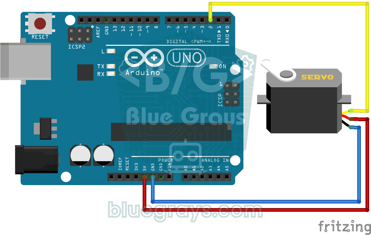
The arm of a small servo motor turns to three positions in turn: all the way to the start, right to the middle and all the way to the end, waiting two seconds at each stop. The Arduino tells the motor
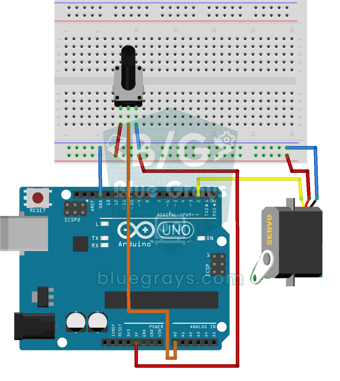
Servo Motor Operation with Potentiometer
As you turn the potentiometer knob, the servo motor's arm turns right along with it: one end of the knob means zero degrees, the other end means half a turn. The Arduino keeps reading the knob's posit
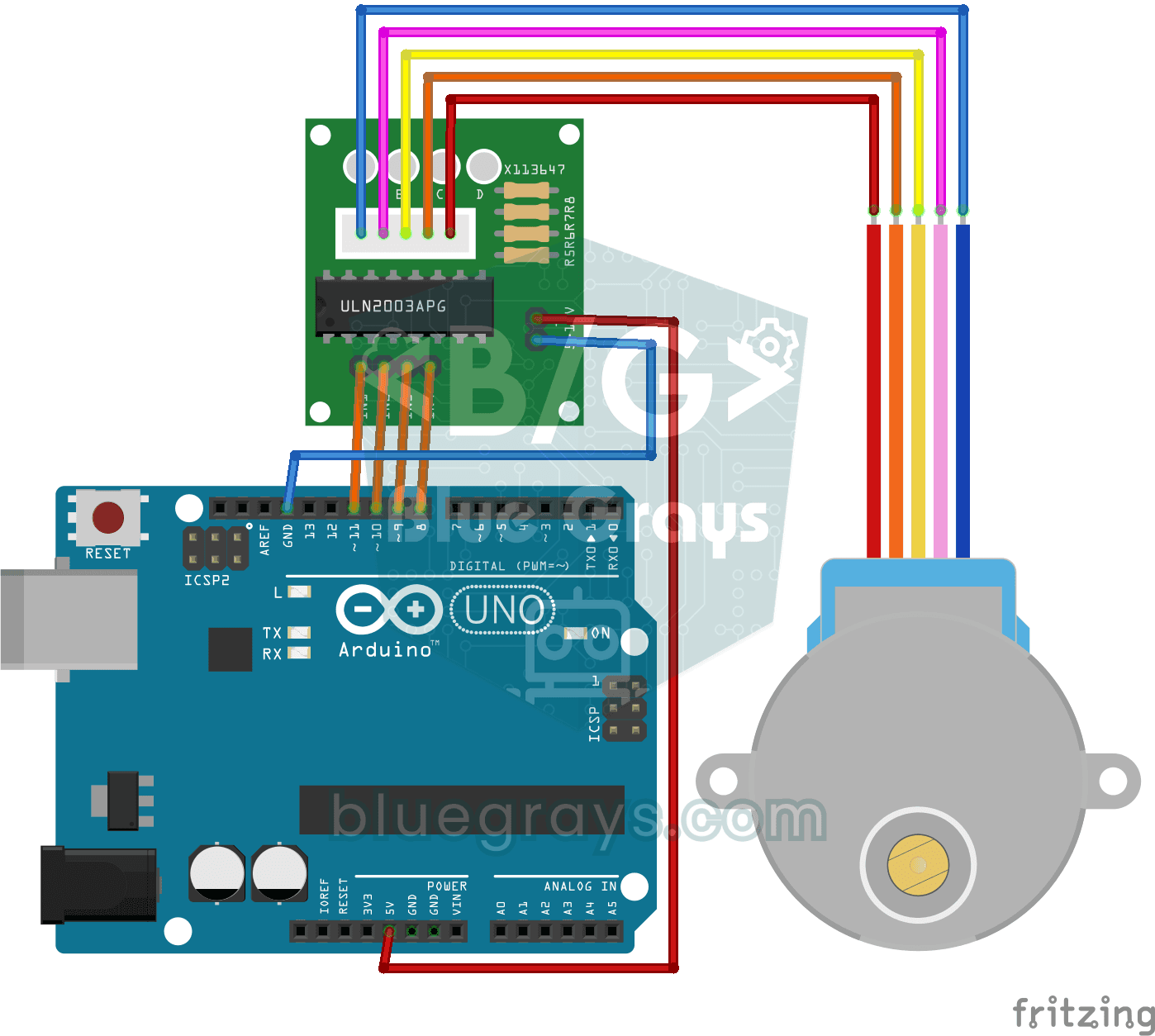
Using a Stepper Motor
A motor that turns step by step, exactly as far as you want, like the hand of a clock. Through a driver board, the Arduino turns a small stepper motor one full turn in one direction, waits a second, t
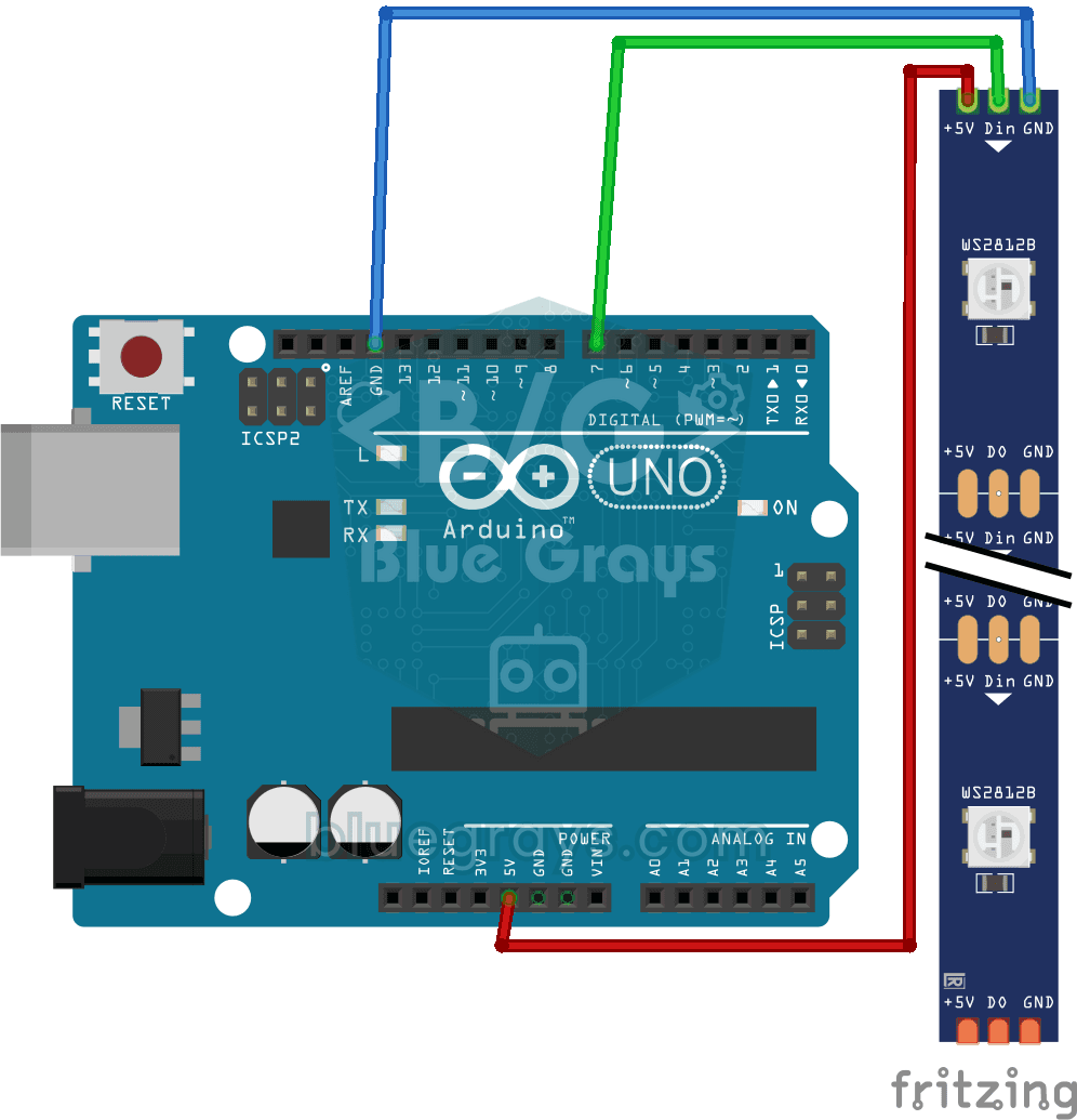
Using a WS2812B LED Strip
Meet a smart LED strip where you can colour every single light on its own. The Arduino first lights the first five LEDs red, a second later turns the other five blue, then switches them all off and st

Bluetooth Controlled Car with L298N
Turn your phone into a remote and drive your own robot car. The Arduino receives commands from a remote-control app on your phone through a Bluetooth module and spins the wheels with a motor driver; t