
7805 Voltage Regulator: Pinout, Capacitors and Heat Calculation
How to wire a 7805 voltage regulator: pinout, 0.33 µF and 0.1 µF capacitors, dropout, power loss and heatsink math, 78xx series, AMS1117-3.3 and buck vs linear.
The 7805 voltage regulator is a cheap three-pin chip that takes a higher or unsteady voltage anywhere between 7 and 35 V and turns it into a steady 5 V. It's the easiest way to get clean 5 V for an Arduino, sensors and relay boards from a 12 V adapter, a car battery or a battery pack: all you add is two small capacitors. But the 7805 works by turning the extra voltage into heat, so knowing the right wiring, the input voltage limits and how hot it will get is the key to a circuit that runs safely.
In this guide you'll learn step by step what a voltage regulator is, the 7805 pinout and how to wire it with 0.33 µF and 0.1 µF capacitors, what dropout voltage means, how to calculate heat with P = (Vin − Vout) · I and how to choose a heatsink. Then we'll look at the 78xx family, the AMS1117-3.3 LDO for 3.3 V modules, the difference between linear and switching (buck) regulators, the Arduino's own regulator and its Vin limit, and finish with code that measures your regulator with an Arduino, an ESP32 and a Raspberry Pi Pico.
What is a voltage regulator and how does it work?
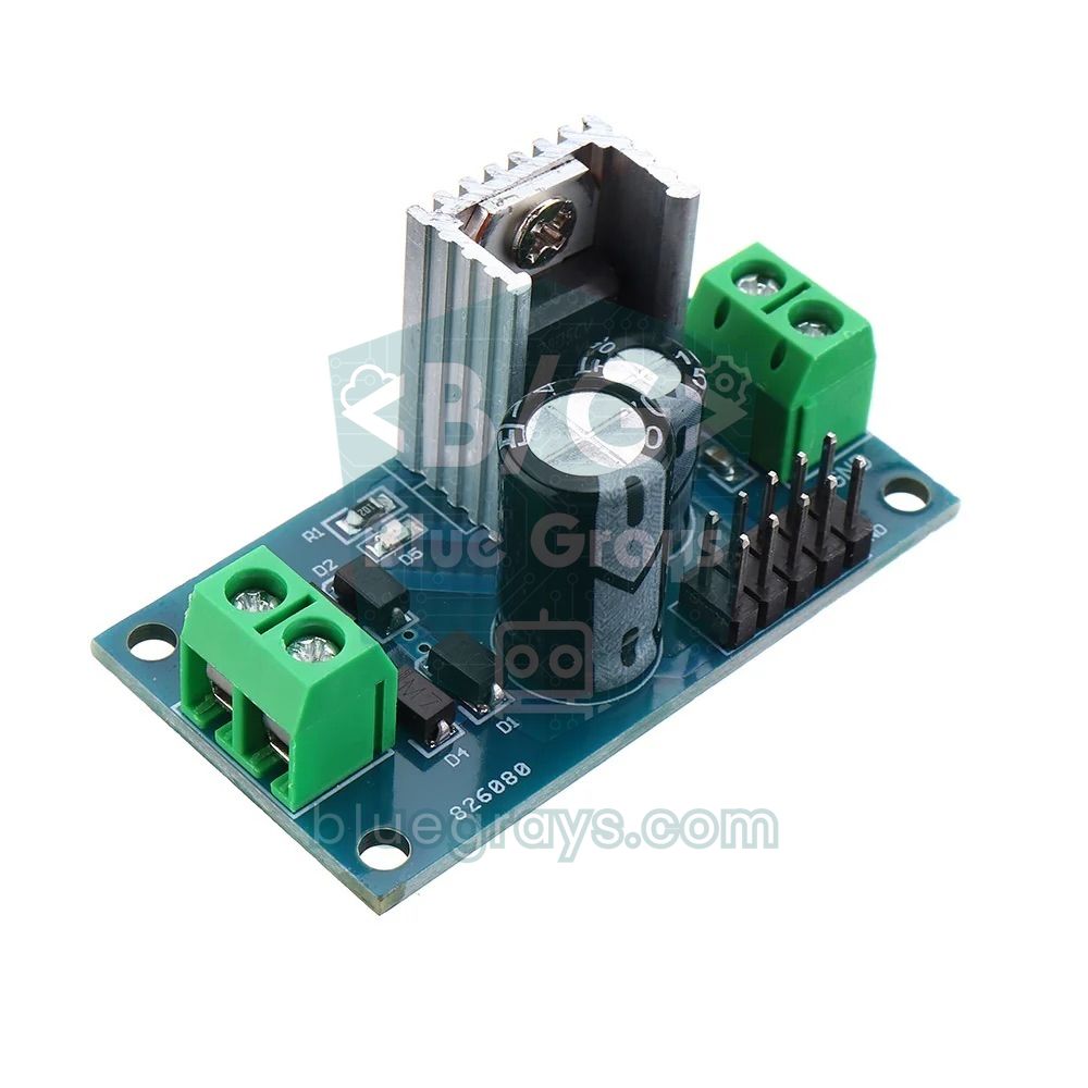
A voltage regulator is a circuit that holds a constant voltage at its output even when the input voltage or the load current changes. The 7805 is a linear regulator: inside there's a power transistor in series between input and output, an internal reference voltage that doesn't drift with temperature, and an error amplifier that constantly compares the output with that reference. If the output drops below 5 V, the transistor conducts a little more; if it rises above, the transistor throttles back. In short, the transistor behaves like a self-adjusting resistor that drops the extra voltage between input and output across itself. That extra voltage multiplied by the current becomes heat, which is both why the 7805 is so simple and why it gets warm.
The last two digits of the 78 family tell you the output voltage: a 7805 gives 5 V, a 7812 gives 12 V. The letters in front only identify the manufacturer, so the LM7805, L7805CV, MC7805 and KA7805 all do the same job. The chip has built-in current limiting, thermal shutdown when it overheats and safe-operating-area protection. That's why it rarely dies even if the output is shorted: it simply limits the current or switches off until it cools down.
| Parameter | Value |
|---|---|
| Output voltage | 5 V (±4%: 4.8–5.2 V) |
| Input voltage | 7–25 V recommended, absolute maximum 35 V |
| Dropout (minimum difference) | Typically 2 V (at 1 A) |
| Output current | 1 A, up to 1.5 A with good cooling |
| Short-circuit current | About 2 A (internal limit) |
| Quiescent current (Iq) | Typically 3–5 mA, 8 mA max |
| Thermal resistance (TO-220) | Junction to case 4–5 °C/W, to air without heatsink 50–65 °C/W |
| Thermal protection | Shuts down at a junction temperature of about 150 °C |
| Packages | TO-220 (1 A), D2PAK, DPAK; the small 78L05 in TO-92 (100 mA) |
7805 pinout and wiring diagram
Hold the 7805 with the printed side facing you and the legs pointing down, and the pins from left to right are 1: Input (IN), 2: GND and 3: Output (OUT). The metal tab with the hole is also connected to GND, so you can bolt the 7805 to a heatsink or metal case tied to the circuit's ground without an insulator. The GND on the input side and the GND on the output side are the same point: the supply, the regulator and the board you're powering must meet at a common ground. The table below shows where the 7805 output goes on each board.
| 7805 pin | Connects to | Arduino Uno | ESP32 DevKit | Raspberry Pi Pico |
|---|---|---|---|---|
| 1 – Input (IN) | Positive of the 7–25 V supply + 0.33 µF | Not connected | Not connected | Not connected |
| 2 – GND | Supply negative and the common side of the capacitors | GND | GND | GND (e.g. pin 38) |
| 3 – Output (OUT) | 5 V rail + 0.1 µF | 5V pin | 5V (VIN) pin | VSYS (pin 39), through a Schottky diode |
Capacitors: why 0.33 µF and 0.1 µF?
The standard circuit in the manufacturers' datasheets uses a 0.33 µF capacitor on the input and a 0.1 µF capacitor on the output (some manufacturers list 0.22 µF on the input). The input capacitor prevents oscillation caused by wire inductance when the regulator sits far from the power supply's filter capacitor. The output capacitor isn't required for stability, but it keeps the voltage steadier during sudden load changes. Both should be ceramic and placed as close to the pins as possible. A 0.33 µF ceramic capacitor is marked 334 and a 0.1 µF one 104; to decode other markings, use the capacitor code calculator.
In practice it's a good habit to add an electrolytic next to each of these small capacitors: 10–100 µF on the input smooths ripple from the supply, and 10–47 µF on the output reduces voltage dips with loads that draw sudden current, such as servos, relays or Wi-Fi modules. If you put more than 10 µF on the output, add a 1N4001 diode from output to input (reverse-biased in normal operation) in case the input gets shorted: if the input suddenly drops to zero, the large capacitor discharges through this diode instead of through the regulator. A second 1N4001 in series with the input protects against reverse polarity, but adds about 0.7 V of drop. For types and orientation, see what is a capacitor and what is a diode.
Step by step: a 5 V supply with a 7805 on a breadboard
- Plug the 7805 into the breadboard with each leg in a separate column and the printed side facing you.
- Connect the supply positive (e.g. a 9 V adapter) to pin 1, the input, and the negative to pin 2, GND. If you like, add a 1N4001 in series with the positive line to protect against reverse polarity.
- Fit the 0.33 µF (334) ceramic capacitor between input and GND, in the holes closest to the pins.
- Fit the 0.1 µF (104) ceramic capacitor and an optional 10–47 µF electrolytic between the output (3) and GND; the electrolytic's long leg goes to positive.
- Before connecting a load, measure the output with a multimeter: you should see 4.8–5.2 V.
- Connect the output to the Arduino's 5V pin and GND to the Arduino's GND. Avoid using USB and the external supply at the same time while uploading code.
- After a few minutes of running, check the regulator's temperature; if it gets very hot, add a heatsink based on the heat calculation below or lower the input voltage.
Dropout voltage: what's the minimum input voltage?
For a linear regulator to hold its output steady, the input has to be a certain amount higher than the output; that minimum difference is called the dropout voltage. The 7805's typical dropout is 2 V at 1 A, so for a 5 V output you need at least 7 V on the input, and the datasheet test conditions also start at 7–7.5 V. If the difference falls below that, the regulator can no longer regulate and the output just follows the input about 2 V lower: with 6 V in, the output sags to around 4 V, the Arduino resets or analog readings drift.
What matters is not the average but the lowest point of the input. In a classic supply made of a transformer, bridge rectifier and filter capacitor, the voltage ripples every half cycle; the ripple is roughly ΔV = I / (100 · C) (50 Hz mains, full-wave rectification; use 120 instead of 100 on 60 Hz mains). With a 500 mA load and a 2200 µF capacitor, ΔV ≈ 2.3 V. A rectified 9 V AC transformer peaks at about 11.3 V, so the bottom of the ripple stays around 9 V; that's above 7 V, so it's enough. By the same logic, a 9 V battery quickly drops below 7 V under load, which is why powering a 7805 from a 9 V battery doesn't last long. For battery options, see the guide on powering an Arduino with batteries.
Heat calculation: P = (Vin − Vout) · I
The current a 7805 draws at its input is almost the same as the current it delivers at its output; the only difference is a few milliamps of quiescent current. So the power turned into heat in the regulator is P = (Vin − Vout) · I, and the efficiency is roughly Vout / Vin. Example: powering a circuit that draws 500 mA from a 12 V adapter produces P = (12 − 5) × 0.5 = 3.5 W of heat. For 2.5 W delivered to the load, 3.5 W is wasted and the efficiency is only 42%. Power the same circuit from a 7.5 V supply and the loss drops to 1.25 W. In other words, a higher input voltage than necessary does nothing but load the regulator with extra heat. To brush up on current, voltage and power, have a look at the Ohm's law article.
| Input (Vin) | 100 mA | 300 mA | 500 mA | 1 A |
|---|---|---|---|---|
| 7 V | 0.2 W | 0.6 W | 1.0 W | 2.0 W |
| 9 V | 0.4 W | 1.2 W | 2.0 W | 4.0 W |
| 12 V | 0.7 W | 2.1 W | 3.5 W | 7.0 W |
| 24 V | 1.9 W | 5.7 W | 9.5 W | 19 W |
Choosing a heatsink
The junction temperature is Tj = Tambient + P · θ, where θ (theta) is the thermal resistance in °C/W. A TO-220 package without a heatsink has a junction-to-air thermal resistance of 50–65 °C/W: a 1 W loss lifts the chip 50–65 °C above ambient. In a safe design the junction stays below 125 °C, which means about 1.5 W at most without a heatsink in a 25 °C room. If the inside of your enclosure warms up to 50–60 °C, the limit drops to 1 W. Any case in the table above that exceeds 1 W should make you think about a heatsink.
For more power, calculate the heatsink's thermal resistance: θtotal = θJC + θCS + θSA. For the 7805, junction to case θJC is about 5 °C/W, and case to heatsink θCS with thermal paste is about 0.5–1 °C/W. In the 3.5 W example, keeping the junction at 110 °C inside a 40 °C enclosure requires θtotal ≤ (110 − 40) / 3.5 = 20 °C/W, so the heatsink itself must be θSA ≤ 20 − 5 − 1 = 14 °C/W. Small clip-on TO-220 heatsinks are usually 20–30 °C/W, so they won't do; you need a medium finned aluminium heatsink. Heatsink manufacturers list this value in °C/W in their catalogues.
- Use thermal paste: the thin air gap between the package and the heatsink seriously reduces heat transfer; a thin layer of paste is enough.
- The tab is GND: on the 78xx the metal tab is connected to GND, so the heatsink doesn't need insulating and several 78xx can share one heatsink. On the 79xx the tab is connected to the input and must be insulated with a mica washer and a plastic bushing.
- Don't rely on thermal protection: an overheating 7805 shuts itself down and switches back on when it cools. The output cuts out every few seconds and the Arduino keeps resetting; that's a last-resort protection, not normal operation.
- Split the heat: the most effective fix is lowering the input. To get 5 V from 24 V, first drop to 7–8 V with a buck converter and use the 7805 as the final stage.
The 78xx series: 7805, 7809, 7812 and more
| Model | Output | Minimum input | Maximum input | Typical use |
|---|---|---|---|---|
| 7805 | 5 V | 7 V | 35 V | Arduino, sensors, relay boards |
| 7808 | 8 V | 10.5 V | 35 V | Intermediate supply for an Arduino's Vin |
| 7809 | 9 V | 11.5 V | 35 V | 9 V circuits, Arduino Vin |
| 7812 | 12 V | 14.5 V | 35 V | 12 V fans and relays (low current) |
| 7815 | 15 V | 17.5 V | 35 V | Op-amp circuits |
| 7824 | 24 V | 27 V | 40 V | 24 V industrial sensors |
| 78L05 | 5 V, 100 mA | 7 V | 30 V | TO-92 package, low-current circuits |
| 7905 | −5 V | −7 V | −35 V | Negative supply (different pin order) |
If you need an adjustable voltage, use the family's cousin, the LM317: with two resistors it gives any output from 1.25 to 37 V, set by Vout = 1.25 × (1 + R2 / R1) (R1 is usually 240 Ω). The heat and dropout rules are the same as for the 7805. The 500 mA 78M05 is the medium-power version you often see on surface-mount boards. Whichever model you choose, the rule stays the same: the minimum input must be about 2–3 V above the output.
AMS1117-3.3 LDO: for 3.3 V modules
The ESP32, Raspberry Pi Pico, nRF24L01 and many sensors run on 3.3 V. You can't get 3.3 V from a 7805; the most common choice for that is the AMS1117-3.3. The AMS1117 is an LDO (low-dropout) regulator: its dropout at 800 mA is typically 1.1 V and at most 1.3 V, so it easily makes 3.3 V from 5 V. It can deliver up to 1 A, accepts at most 15 V on its input and draws about 5 mA at idle. It's also the regulator that drops 5 V to 3.3 V on most ESP32 development boards.
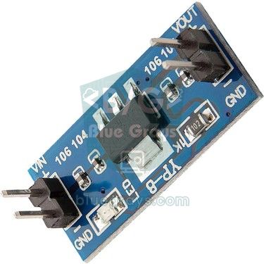
On the AMS1117's SOT-223 package the pin order differs from the 7805: 1: GND/ADJ, 2: Output, 3: Input, and the large tab is connected to the output. The datasheet recommends a 22 µF tantalum capacitor on the output for stability; ready-made modules come with 10 µF capacitors and work fine with normal loads, but if you build your own circuit, put 22 µF on the output. It's more sensitive to heat: the SOT-223 package's thermal resistance is 46–90 °C/W depending on the copper area on the board, and the manufacturer doesn't guarantee regulation beyond about 1.2 W. From 5 V to 3.3 V at 300 mA, P = 1.7 × 0.3 = 0.51 W, which is fine; but from 12 V to 3.3 V the same current means 2.6 W and the module soon goes into thermal shutdown.
| Regulator | Output | Dropout | Max. input | Max. current | Quiescent current |
|---|---|---|---|---|---|
| 7805 (TO-220) | 5 V | ~2 V | 35 V | 1–1.5 A | 3–8 mA |
| AMS1117-3.3 (SOT-223) | 3.3 V | 1.1–1.3 V | 15 V | 1 A | ~5 mA |
| AMS1117-5.0 (SOT-223) | 5 V | 1.1–1.3 V | 15 V | 1 A | ~5 mA |
| MCP1700-3302 (TO-92 / SOT-23) | 3.3 V | ~0.18 V (250 mA) | 6 V | 250 mA | 1.6 µA |
In a project meant to run for months on batteries, quiescent current matters as much as dropout: the AMS1117 draws about 5 mA even when it powers nothing, which is hundreds of times what an ESP32 in deep sleep consumes. The AMS1117's 1.1 V drop is also too much for making 3.3 V from a single Li-ion cell (3.0–4.2 V): even with a fully charged 4.2 V cell the output only reaches about 3.1 V, and it sinks as the battery drains. For these projects, LDOs like the MCP1700, with microamp-level quiescent current and less than 0.2 V of dropout, are the better choice.
Linear or switching (buck)?
A switching buck (step-down) regulator doesn't burn the extra voltage as heat; it switches the input on and off tens of thousands of times per second and transfers the energy to the output by storing it in an inductor and a capacitor. That pushes efficiency to 80–95%, and the current drawn from the input is lower than the output current. For example, LM2596-based modules give an adjustable output of up to 3 A from 4.5–40 V and switch at 150 kHz. The price is a few tens of millivolts of switching ripple on the output, electromagnetic noise and more parts. Setting up and wiring the module is covered in the LM2596 step-down converter article.
| 12 V → 5 V, 1 A load | 7805 (linear) | LM2596 (buck, ~85% efficiency) |
|---|---|---|
| Input current | ≈ 1 A | ≈ 0.49 A |
| Power lost as heat | 7 W | ≈ 0.9 W |
| Efficiency | 42% | ~85% |
| Heatsink | Large heatsink required | Usually not needed |
| Output noise | Very low | Tens of mV of ripple |
| Part count | 1 chip + 2 capacitors | Ready-made module, or inductor, diode and capacitors |
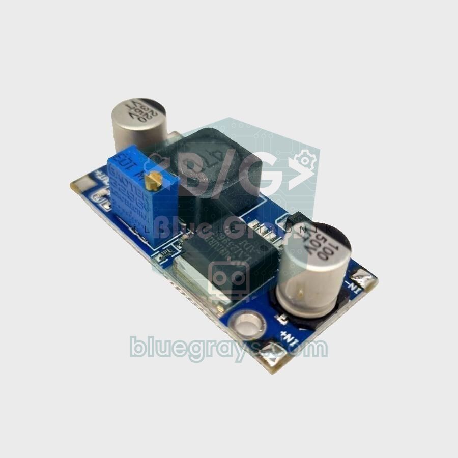
Here's the rule of thumb: if the difference between input and output is small (2–4 V) and the current stays below a few hundred milliamps, a 7805 or an LDO is simple, quiet and cheap. If the difference is large, the current exceeds 500 mA or you're running on batteries, choose a buck converter. When you're powering analog measurements, audio or sensitive sensors, combining the two is also common: first step down to 7–8 V with a buck, then get a low-noise 5 V from a 7805. That way you get both efficiency and a clean supply.
The Arduino's own regulator and the Vin limit
The voltage you feed into the Arduino Uno R3's DC jack or Vin pin goes through an on-board 5 V LDO from the 1117 family (an NCP1117 on the original board, usually an AMS1117 on clones), and behind the jack sits a 4007-type diode that protects against reverse polarity. Arduino recommends 7–12 V, and the board's limit is 6–20 V. The lower limit is about dropout: the diode and regulator together eat about 2 V, so below 7 V the 5V rail sags. The upper limit is about heat: with 12 V on Vin and 200 mA drawn, the small SOT-223 regulator produces (12 − 5) × 0.2 = 1.4 W and gets too hot to touch. At 20 V the same load means 3 W.
| Board | On-board regulator | Recommended input | Limit |
|---|---|---|---|
| Arduino Uno R3 / Mega | 5 V LDO (1117 family) | 7–12 V (jack or Vin) | 6–20 V |
| Arduino Nano | 5 V LDO (mostly AMS1117 on clones) | 7–12 V (Vin) | 6–20 V |
| Arduino Uno R4 | Switching (buck) converter | 6–24 V (jack or Vin) | 24 V |
| ESP32 DevKit | 3.3 V LDO (usually AMS1117) | 5 V (USB or 5V pin) | Stay below 6 V because of heat |
| Raspberry Pi Pico | Buck-boost (switching) | VSYS: 1.8–5.5 V | 5.5 V |
You can also take power from the board's 5V pin, but that current goes through the same regulator. On USB power the 5V rail comes straight from USB and is limited by a 500 mA fuse; when powered from the jack, the limit is set by the regulator's heat. That's why you should power loads such as servos, LED strips or motors from a separate 7805 or buck module, not from the Arduino's 5V pin, and tie the grounds together. The 3.3V pin can only supply 50 mA; for power-hungry modules such as the ESP-01 or an nRF24L01 with antenna, use a separate AMS1117-3.3. For the pin layout, see the Arduino Uno pinout article.
Testing the regulator with an Arduino: input, output and heat
The code below measures the 7805's input and output voltage, prints the difference, the power dissipated and the estimated junction temperature to the Serial Monitor, and warns you when it gets close to dropout or needs a heatsink. The input voltage is above 5 V, so it can't go straight to an analog pin: connect the input to A0 through a 100 kΩ and 22 kΩ voltage divider (it measures up to about 27 V), and the output to A1 through two 10 kΩ resistors. You can check the ratios for your own resistors with the voltage divider calculator. All grounds must be common.
1// 7805 test istasyonu: giriş, çıkış ve ısı / 7805 test bench: input, output and heat
2// Kart: Arduino Uno / Nano (ATmega328P) / Board: Arduino Uno / Nano (ATmega328P)
3
4const float R1_IN  = 100000.0;  // giriş bölücü üst direnç / input divider top resistor
5const float R2_IN  = 22000.0;   // giriş bölücü alt direnç / input divider bottom resistor
6const float R1_OUT = 10000.0;   // çıkış bölücü üst direnç / output divider top resistor
7const float R2_OUT = 10000.0;   // çıkış bölücü alt direnç / output divider bottom resistor
8
9const float LOAD_A    = 0.30;   // multimetreyle ölçtüğün yük akımı (A) / load current measured with a multimeter (A)
10const float THETA_JA  = 60.0;   // soğutucusuz TO-220, °C/W / TO-220 without heatsink, °C/W
11const float T_AMBIENT = 30.0;   // ortam sıcaklığı (°C) / ambient temperature (°C)
12const float DROPOUT_V = 2.0;    // 7805 için gereken en az fark (V) / minimum headroom for the 7805 (V)
13
14// Gerçek besleme gerilimini dahili 1,1 V referansla ölçer (mV)
15// Measures the real supply voltage with the internal 1.1 V reference (mV)
16long readVcc() {
17  ADMUX = _BV(REFS0) | _BV(MUX3) | _BV(MUX2) | _BV(MUX1);  // referans AVcc, kanal 1,1 V / AVcc reference, 1.1 V channel
18  delay(2);                                               // referansın oturmasını bekle / let the reference settle
19  ADCSRA |= _BV(ADSC);                                    // dönüşümü başlat / start a conversion
20  while (bit_is_set(ADCSRA, ADSC));                       // bitmesini bekle / wait until it finishes
21  long raw = ADCL;                                        // önce ADCL okunmalı / ADCL must be read first
22  raw |= ADCH << 8;
23  return 1125300L / raw;                                  // 1,1 x 1023 x 1000
24}
25
26// Bölücünün arkasındaki gerçek gerilimi hesaplar / Calculates the real voltage behind a divider
27float readVolts(uint8_t pin, float vcc, float r1, float r2) {
28  analogRead(pin);                                        // ilk okumayı at / discard the first reading
29  long sum = 0;
30  for (int i = 0; i < 16; i++) sum += analogRead(pin);    // 16 örneğin ortalaması / average of 16 samples
31  float vPin = (sum / 16.0) * vcc / 1023.0;
32  return vPin * (r1 + r2) / r2;
33}
34
35void setup() {
36  Serial.begin(9600);
37}
38
39void loop() {
40  float vcc  = readVcc() / 1000.0;
41  float vin  = readVolts(A0, vcc, R1_IN, R2_IN);
42  float vout = readVolts(A1, vcc, R1_OUT, R2_OUT);
43
44  float headroom = vin - vout;                    // regülatör üzerindeki gerilim / voltage across the regulator
45  float heatW    = headroom * LOAD_A;             // P = (Vin - Vout) x I
46  float tj       = T_AMBIENT + heatW * THETA_JA;  // tahmini yonga sıcaklığı / estimated junction temperature
47  float eff      = (vin > 1.0) ? 100.0 * vout / vin : 0.0;  // verim (%) / efficiency (%)
48
49  Serial.print(F("Vin "));      Serial.print(vin, 2);
50  Serial.print(F(" V | Vout ")); Serial.print(vout, 2);
51  Serial.print(F(" V | Fark ")); Serial.print(headroom, 2);
52  Serial.print(F(" V | Isi "));  Serial.print(heatW, 2);
53  Serial.print(F(" W | Tj ~"));  Serial.print(tj, 0);
54  Serial.print(F(" C | Verim %")); Serial.println(eff, 0);
55
56  if (headroom < DROPOUT_V) Serial.println(F("UYARI: giris dusuk, dropout / WARNING: input too low, dropout"));
57  if (tj > 125.0)           Serial.println(F("UYARI: sogutucu gerekli / WARNING: heatsink required"));
58  delay(1000);
59}
Instead of assuming the supply voltage that the analog readings are referenced to, the code measures it with the readVcc() function: it reads the ATmega328P's internal fixed reference of about 1.1 V and works back to the real Vcc. That keeps the readings correct whether the Arduino runs from USB or from the 7805 itself. This method is for ATmega328P boards such as the Uno and Nano; since the internal reference can vary by about ±10% from chip to chip, compare the result once with a multimeter and adjust the 1125300 constant. Enter the load current you measured with a multimeter in LOAD_A; if you fitted a heatsink, replace THETA_JA with the total thermal resistance from your heatsink calculation.
ESP32: the AMS1117 and Wi-Fi current spikes
ESP32 development boards drop the 5 V input to 3.3 V with an on-board LDO. The board normally draws 50–100 mA, but during Wi-Fi transmission the current briefly jumps to around 300 mA, which is why Espressif recommends a supply that can deliver at least 500 mA. A weak supply, a thin and long USB cable or a hot regulator collapses the 3V3 rail during that spike, and the ESP32 prints "Brownout detector was triggered" to the Serial Monitor and resets itself. The code below tells you whether the last reset was caused by a brownout and records the lowest voltage the 3V3 rail sees while connecting to Wi-Fi. Connect the 3V3 pin to GPIO 34 through a divider made of two 10 kΩ resistors.
1// ESP32: 3V3 hattını ve brownout resetini izle / ESP32: watch the 3V3 rail and brownout resets
2#include <WiFi.h>
3#include "esp_system.h"
4
5const char* WIFI_SSID = "AgAdi";   // Wi-Fi ağ adı / Wi-Fi network name
6const char* WIFI_PASS = "Sifre";   // Wi-Fi şifresi / Wi-Fi password
7const int SENSE_PIN = 34;          // 3V3 -> 10k -> GPIO34 -> 10k -> GND (yalnız giriş, ADC1) / input-only ADC1 pin
8
9int minMv = 9999;                  // görülen en düşük gerilim (mV) / lowest voltage seen (mV)
10
11int rail3v3() {
12  return analogReadMilliVolts(SENSE_PIN) * 2;  // bölücü yarıya indirir / the divider halves it
13}
14
15void setup() {
16  Serial.begin(115200);
17  delay(300);
18  if (esp_reset_reason() == ESP_RST_BROWNOUT) {
19    Serial.println("Son reset: BROWNOUT, besleme yetersiz / Last reset: BROWNOUT, weak supply");
20  }
21  Serial.printf("Wi-Fi oncesi 3V3: %d mV\n", rail3v3());
22
23  WiFi.begin(WIFI_SSID, WIFI_PASS);
24  unsigned long t0 = millis();
25  while (WiFi.status() != WL_CONNECTED && millis() - t0 < 15000) {
26    int mv = rail3v3();                        // bağlanırken sürekli ölç / keep sampling while connecting
27    if (mv < minMv) minMv = mv;
28    delay(1);
29  }
30  Serial.printf("Baglanirken en dusuk 3V3: %d mV\n", minMv);
31}
32
33void loop() {
34  int mv = rail3v3();
35  if (mv < minMv) minMv = mv;
36  Serial.printf("3V3: %d mV | en dusuk / min: %d mV\n", mv, minMv);
37  delay(1000);
38}
If the minimum during connection drops below 3.0 V, the supply isn't good enough. The ADC can't catch every very short dip, but it clearly shows the trend. The fix is usually simple: a short, thick USB cable, a 470 µF electrolytic capacitor between 5V and GND close to the board, or a supply that can deliver at least 500 mA. If you power the ESP32 from 12 V, don't feed 12 V into the board's AMS1117; step it down to 5 V with a buck module first. For detailed troubleshooting, see the ESP32 brownout and Guru Meditation errors article.
Raspberry Pi Pico: VSYS and the 7805
The Raspberry Pi Pico has an efficient buck-boost converter instead of a linear regulator, and its VSYS pin accepts anything from 1.8 to 5.5 V. To run a Pico in a 12 V system you can connect the 7805 output to VSYS; if you'll use USB at the same time, put a Schottky diode such as a 1N5819 in between, otherwise USB's 5 V and the 7805 will fight each other. Never connect the 7805 output to the 3V3 pin; that pin can't take more than 3.3 V. The MicroPython code below measures the 7805's input through a divider on GP26, and VSYS through the on-board GP29 channel.
1# Pico: 7805 girişini ve VSYS'i ölç / Pico: measure the 7805 input and VSYS
2from machine import ADC
3import time
4
5adc_in = ADC(26)            # GP26 (ADC0): 100k/22k bölücü / 100k/22k divider
6adc_vsys = ADC(29)          # GP29 (ADC3): kart üzerinde VSYS/3 / VSYS/3 on the board
7
8K_IN = (100 + 22) / 22      # bölücü oranı (~5,55) / divider ratio (~5.55)
9V_OUT = 5.0                 # 7805 çıkışı (V) / 7805 output (V)
10LOAD_A = 0.30               # ölçtüğün yük akımı (A) / load current you measured (A)
11
12def volts(adc, ratio, n=16):
13    total = 0
14    for _ in range(n):
15        total += adc.read_u16()          # 0-65535 arası ham değer / raw value 0-65535
16    return total / n * 3.3 / 65535 * ratio
17
18while True:
19    vin = volts(adc_in, K_IN)
20    vsys = volts(adc_vsys, 3)
21    heat = (vin - V_OUT) * LOAD_A        # P = (Vin - Vout) x I
22    print("Vin {:.2f} V | VSYS {:.2f} V | 7805 isi {:.2f} W".format(vin, vsys, heat))
23    if vin - V_OUT < 2.0:
24        print("UYARI: dropout / WARNING: dropout")
25    time.sleep(1)
The Pico's ADC reads at most 3.3 V, so with a 100k/22k divider you can measure up to about 18 V. The VSYS value comes out a little lower than the 7805 output because of the Schottky diode's drop of about 0.3 V; that's normal. On a Pico W, GP29 is shared with the wireless chip, so measuring VSYS needs extra setup; in that case use only the GP26 reading. If you're new to the Pico, the What is the Raspberry Pi Pico? article is a good place to start.
Project ideas with the 7805 and other regulators
- Bench 5 V supply: build a small box with a 12 V adapter, a 7805, a heatsink and a switch that gives your breadboard projects a steady 5 V.
- Supply with voltage and heat readout: move the test code above to an LCD and show input, output and loss live; the basic measuring idea is in the Arduino voltmeter article.
- Arduino in a car: step the 12–14.4 V battery voltage down to 7–8 V with a buck, then to 5 V with a 7805; add a TVS diode on the input against voltage spikes in the vehicle.
- 12 V LED strip and relay control: run the strip straight from 12 V, and power the Arduino and the relay module from the 7805 output.
- Separate rail for servos and NeoPixels: use a 7805 for loads under 1 A and a buck above that to power servo motors and WS2812B LEDs from a separate 5 V rail with a common ground.
- 3.3 V sensor board: power 3.3 V modules such as the BME280 and nRF24L01 from an AMS1117-3.3 independently of the Arduino; use a logic level converter for the signal levels.
Common mistakes and how to fix them
| Symptom | Likely cause | Fix |
|---|---|---|
| 3.5–4.5 V on the output instead of 5 V | Input below 7 V (dropout) or a weak battery | Raise the input to 7.5–9 V and measure under load |
| The 7805 runs for a few seconds and cuts out | Thermal protection is kicking in, the loss is too high | Add a heatsink, lower the input or use a buck |
| Output equals the input (e.g. 12 V) | Broken GND leg, or the regulator has failed short inside | Check the GND connection; disconnect the load and measure, replace if needed |
| Output is 0 V and the regulator stays cold | Wrong pin order (78L05 or 7905 mixed up), or input and output swapped | Verify the pin order for the package |
| The Arduino resets at random | Capacitors missing or far from the pins | Fit the 0.33 µF and 0.1 µF close to the pins and add a 10–47 µF electrolytic |
| The Arduino's regulator runs very hot | 12 V on Vin and a lot of current drawn from the 5V pin | Power loads from a separate 7805 or buck; keep Vin at 7–9 V |
| The ESP32 resets when Wi-Fi starts | The supply or the AMS1117 can't cover the peak current | Short cable, 470 µF capacitor, a supply of at least 500 mA |
| AMS1117-3.3 output is around 3 V | Input below 4.4 V (e.g. a single Li-ion cell) | Feed it 5 V or pick a low-dropout LDO |
With the right input voltage, two small capacitors and a heatsink when needed, the 7805 is one of the most reliable parts in electronics and will run for years. Remember the rule: the bigger the difference between input and output, the more heat. For large differences pick a buck, for 3.3 V an AMS1117, and for long battery life an LDO with low quiescent current. In the BlueGrays app you'll find the digital voltmeter with LCD, the Bluetooth-controlled L298N car, the obstacle-avoiding robot, the smart watering station and the ESP32 deep sleep projects with step-by-step circuit diagrams and code, and you can build their power stage yourself with the calculations in this guide.
Frequently asked questions
Which pin of the 7805 is input and which is output?
With the printed side facing you and the legs pointing down, from left to right pin 1 is the input (IN), pin 2 is GND and pin 3 is the output (OUT). The metal tab is also connected to GND. On the TO-92 78L05 the order is reversed (1 output, 2 GND, 3 input), so always check the package.
How much current can a 7805 supply?
A TO-220 7805 with a good heatsink can supply 1 A, and up to 1.5 A depending on conditions; its internal current limit kicks in at about 2 A on a short circuit. In practice the limit is heat, not current: without a heatsink, (Vin − Vout) · I should stay below 1–1.5 W. The small 78L05 supplies only 100 mA.
Why does my 7805 get hot, and do I need a heatsink?
The 7805 is a linear regulator, so it turns the extra voltage between input and output into heat. Drawing 500 mA with a 12 V input means 3.5 W of heat, which is impossible without a heatsink. If the loss is below 1 W you don't need one; above that use a heatsink, and beyond a few watts use a buck converter.
Does a 7805 work without capacitors?
It often works with short wires close to a well-filtered supply, but it's not recommended. The 0.33 µF on the input prevents oscillation caused by the wiring, and the 0.1 µF on the output steadies the voltage during sudden load changes. These two cheap capacitors prevent unexplained resets and noise.
What is the maximum input voltage of a 7805?
The absolute maximum is 35 V (40 V for the 7824), but running close to that limit isn't practical because of the heat. For a 5 V output, 7.5–12 V on the input is ideal. With high voltages such as 24 V, it's much smarter to step the voltage down with a buck converter first.
Can a 7805 give 3.3 V?
No, the 7805 only gives 5 V. For 3.3 V you use an LDO such as the AMS1117-3.3, which easily makes 3.3 V from a 5 V input and supplies up to 1 A. For battery-powered projects, LDOs with microamp-level quiescent current such as the MCP1700 are a better fit.
Projects to build after reading this
See all projects
Digital Voltmeter with LCD Display
Find out how much voltage a battery or power adapter gives with a meter you built yourself. A divider made of two resistors brings high voltage down to a level the board can read, and the Arduino calc

Bluetooth Controlled Car with L298N
Turn your phone into a remote and drive your own robot car. The Arduino receives commands from a remote-control app on your phone through a Bluetooth module and spins the wheels with a motor driver; t

Obstacle Avoidance Robot
How about building a smart vehicle that finds its own way? The Obstacle Avoidance Robot constantly scans its surroundings thanks to the ultrasonic sensor in front of it. When it encounters an obstacle

Smart Irrigation Station
A gardener that waters your plants on its own, so they don't dry out while you're on vacation. A soil moisture sensor measures how wet the soil is; when it gets dry, the Arduino runs the water pump fo

ESP32 Deep Sleep — Battery Saving (OLED + RTC RAM Counter)
The ESP32's Deep Sleep mode reduces current consumption to ~10 µA by shutting down the CPU and most peripherals, making it critical for battery-powered IoT devices. In this project, we use three different wake-up sources: a timer (15 seconds), an external pin (EXT0 — button GPIO 33), and touch (T0/GPIO 4). Variables marked with RTC_DATA_ATTR are preserved during deep sleep—the boot counter, timer wake counter, and button wake counter are continuously tracked. On each wake-up, the SSD1306 OLED

ESP32 Wi-Fi STA Connection (with LCD Screen)
In this project, we connect the ESP32 to the home Wi-Fi network in Station (STA) mode in a secure, fault-tolerant manner. We store the SSID and password in a separate secrets.h file to prevent leaking to Git, set up an auto-reconnect mechanism, and display the RSSI signal level and IP address on an I2C LCD screen. The internal LED works as a status indicator. It is a production-grade connection manager.

ESP32 WS2812B NeoPixel Strip Control
WS2812B (NeoPixel) addressable LEDs are smart RGB LEDs that can be controlled in a daisy-chain configuration via a single data pin. In this project, we will control an 8-LED WS2812B strip using the Adafruit_NeoPixel library to create a smooth rainbow animation. While the ESP32’s 3.3V logic level works seamlessly with most WS2812B components, we’ll demonstrate a solution using a 470Ω series resistor and a 1000µF capacitor in case of instability. The animation is achieved by shifting the hue value