
NodeMCU Projects: 15 ESP8266 and Wemos D1 mini Wi-Fi Projects
15 NodeMCU projects: Wi-Fi relay, weather station, Alexa, WLED, Tasmota, deep sleep sensor; ESP8266 limits, a when-to-switch-to-ESP32 table and two sketches.

NodeMCU projects use the built-in Wi-Fi of this cheap ESP8266 board to switch a lamp from your phone, send a sensor reading to the internet or control an LED strip over your home network. Everything also applies to the Wemos D1 mini, which carries the same chip; the differences between the two boards are size and a few hardware details. The ESP8266 may live in the ESP32's shadow, but for a single relay, a single sensor or a small battery-powered measuring device it is still one of the cheapest and most trouble-free options. What matters is knowing from the start where it is enough and where it runs out of breath.
In this guide we collect 15 projects, from easy to hard, in one table with their parts, the software they use and whether the ESP8266 is up to the job. Then we explain projects such as a Wi-Fi relay, Alexa control, WLED, Tasmota, ESPHome and a battery-powered sensor one by one, and give you two ready sketches: a relay panel you open on your phone and a sensor that takes a reading and goes into deep sleep. If you are using the board for the first time, set it up with the NodeMCU ESP8266 guide first; for pin details see the Wemos D1 mini pinout guide.
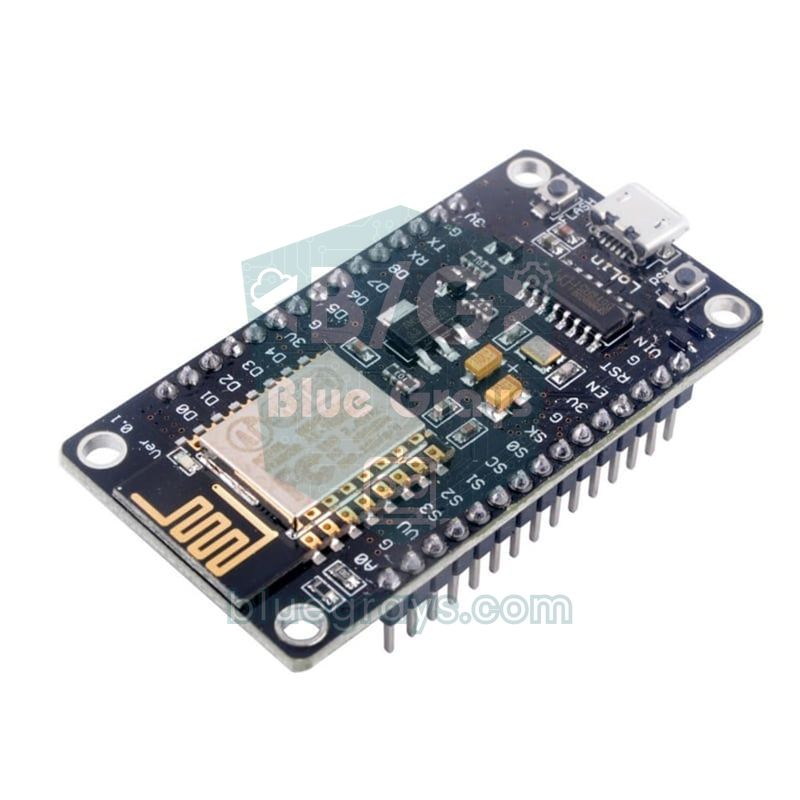
NodeMCU and Wemos D1 mini: same chip, two different boards
Both boards are built around the ESP8266EX chip running at 80 MHz (160 MHz if you like) with 4 MB of flash, and both are programmed with the same code in the Arduino IDE. The NodeMCU is larger, its pin labels are easy to read, and on a breadboard it leaves one row of free holes on each side, which makes it comfortable for first experiments. The Wemos D1 mini is half the size, and its stackable shields (relay, DHT, OLED, battery) let you build a permanent device with almost no soldering. In a battery project the D1 mini wins, because the board draws less current in deep sleep. If you write pins with board labels such as D1 and D2, the same program runs on both boards unchanged.
| Feature | NodeMCU V3 | Wemos D1 mini |
|---|---|---|
| Chip | ESP8266EX (ESP-12E/F module) | ESP8266EX |
| Size | About 58 × 31 mm | 34.2 × 25.6 mm |
| Usable pins | D0–D8, RX, TX, A0 | D0–D8, RX, TX, A0 |
| USB-serial chip | CH340 or CP2102 | Mostly CH340 |
| Analog input | A0, 0–3.2 V on the board | A0, 0–3.2 V on the board |
| Board current in deep sleep | Higher because of the regulator and USB chip | About 80–200 µA |
| Shield system | None | Relay, DHT, SHT30, OLED, SD, battery shields |
| Best for | Breadboard experiments, learning | Small boxed devices, battery sensors |
ESP8266 limits: one analog pin, 3.3 V and memory
- One analog input: the ESP8266 only has A0. The chip measures 0–1 V, and the 220 kΩ / 100 kΩ divider on the board extends that to 0–3.2 V. For a second analog sensor you need an I2C ADC such as the ADS1115 or an ESP32. For other voltage ranges use the voltage divider tool.
- 3.3 V logic: the pins are not officially 5 V tolerant and should not supply more than about 12 mA each. Bring the signal of 5 V sensors such as the HC-SR04 down with a divider or a level shifter.
- Limited memory: with Wi-Fi connected, about 40–50 KB of RAM is left for your program. A few HTTPS requests plus a large JSON reply fill it quickly.
- Single core and watchdog: Wi-Fi and your code share one core. A loop that runs for seconds inside loop() or a long chain of delay() calls triggers the watchdog and the board reboots; put yield() or a short delay() inside long jobs.
- Boot pins: D3 (GPIO 0) and D4 (GPIO 2) must be HIGH at boot and D8 (GPIO 15) LOW. A button or module on these pins can stop the board from starting; the safe pins are D1, D2, D5, D6 and D7.
- No Bluetooth: the ESP8266 has no Bluetooth hardware. To talk to a phone over Bluetooth or read BLE sensors you need an ESP32.
| What you need | Is the ESP8266 enough? | Why |
|---|---|---|
| Wi-Fi device with one relay or one sensor | Yes | The cheapest and most mature solution for this kind of job |
| Battery sensor that reports now and then | Yes | With deep sleep a D1 mini can last for months |
| Several analog sensors | With an extra ADC | Only one A0; the ESP32 has 18 analog channels |
| Bluetooth or BLE | No | No hardware; use an ESP32 |
| Camera | No | No camera interface or PSRAM; use an ESP32-CAM |
| Frequent HTTPS requests, big JSON | Borderline | RAM can run short; the ESP32's 520 KB is more comfortable |
| More than a few hundred addressable LEDs | Borderline | WLED recommends an ESP32 for long strips and multiple outputs |
| Touch pins, many PWM channels, dual core | No | These features only exist on the ESP32 |
15 NodeMCU and ESP8266 projects in one table
| # | Project | Parts | Software / library | Level |
|---|---|---|---|---|
| 1 | Wi-Fi relay panel | Relay module | ESP8266WebServer | Easy |
| 2 | LED strip dimmer from your phone | 12 V LED strip, logic-level MOSFET | ESP8266WebServer, analogWrite | Easy |
| 3 | Voice-controlled lamp with Alexa | Relay module | Espalexa | Medium |
| 4 | Door sensor with Telegram alerts | Reed switch, magnet | UniversalTelegramBot | Medium |
| 5 | Addressable LEDs (WLED) | WS2812B strip, 5 V adapter | WLED (ready firmware) | Easy |
| 6 | Tasmota smart plug | Relay module | Tasmota (ready firmware) | Easy |
| 7 | ESPHome temperature sensor | DHT22 or BME280 | ESPHome | Easy |
| 8 | Weather station with a web page | BME280 | ESP8266WebServer, Adafruit BME280 | Medium |
| 9 | Deep sleep battery sensor | DHT22, 18650 cell | ESP8266HTTPClient, ThingSpeak | Medium |
| 10 | Soil moisture and watering alert | Capacitive soil moisture sensor | analogRead, Telegram or web | Easy |
| 11 | Clock set from the internet | TM1637 or OLED | NTP (configTime) | Easy |
| 12 | Weather or exchange rate display | 0.96 inch OLED | ESP8266HTTPClient, ArduinoJson | Medium |
| 13 | Wi-Fi IR universal remote | IR LED, transistor, IR receiver | IRremoteESP8266 | Medium |
| 14 | ESP-NOW wireless button | Button, second ESP8266 or ESP32 | espnow.h | Medium |
| 15 | Home Assistant device over MQTT | Relay, sensor | PubSubClient | Medium |
These 15 items are project ideas that really are built and run on the ESP8266; for each one we list the parts and the library you need. The Wi-Fi projects in the BlueGrays app are written for the ESP32, but they teach the same topics: you can move the circuit and logic of ESP32 Wi-Fi STA Connection, ESP32 Async Web Server, ESP32 mDNS, ESP32 Real Time from the Internet with NTP and ESP32 OTA Update to the ESP8266; in the code, the library names (ESP8266WiFi.h instead of WiFi.h, for example) and the pin numbers change.
Wi-Fi control projects (1–4): relay, dimmer, Alexa and Telegram
Project 1 is the foundation of the list: the NodeMCU serves its own web page, and the ON and OFF buttons on it switch the relay. The code below also makes the board reachable as role.local through mDNS, so you type the same address in your phone's browser even if the IP changes (some Android versions do not resolve .local names; use the IP in that case). The /state address returns the relay state as plain text, so another device or an automation can query it. Project 2 adds a brightness slider to the same server: you drive a single-colour 12 V LED strip through a logic-level MOSFET such as the IRLZ44N, and the ESP8266's analogWrite() output sets the brightness from 0 to 255.
| Connection | NodeMCU / D1 mini | Note |
|---|---|---|
| Relay module IN | D1 (GPIO 5) | Safe at boot; on an active-LOW module the code switches it on with LOW |
| Relay module VCC | VIN (5 V from USB) | The relay coil needs 5 V |
| Relay module GND | GND | Common ground |
| Lamp (230 V side) | Relay COM and NO terminals | Only if you are experienced, and inside a closed box |
1// NodeMCU / Wemos D1 mini: telefondan Wi-Fi röle (web panel + mDNS)
2// NodeMCU / Wemos D1 mini: Wi-Fi relay from your phone (web panel + mDNS)
3#include <ESP8266WiFi.h>
4#include <ESP8266WebServer.h>
5#include <ESP8266mDNS.h>
6
7const char* WIFI_SSID = "WIFI_ADIN";      // Wi-Fi adı / Wi-Fi name
8const char* WIFI_PASS = "WIFI_SIFRESI";   // Wi-Fi şifresi / Wi-Fi password
9
10#define RELAY_PIN D1        // GPIO 5, açılışta güvenli / GPIO 5, safe at boot
11#define RELAY_ON  LOW       // çoğu röle modülü LOW ile çeker / most relay modules are active LOW
12#define RELAY_OFF HIGH
13
14ESP8266WebServer server(80);
15bool relayState = false;
16
17void setRelay(bool on) {
18  relayState = on;
19  digitalWrite(RELAY_PIN, on ? RELAY_ON : RELAY_OFF);
20}
21
22void handleRoot() {
23  String html = F("<!DOCTYPE html><html><head><meta name='viewport' content='width=device-width,initial-scale=1'>"
24                  "<title>Role</title><style>body{font-family:sans-serif;text-align:center;margin-top:40px}"
25                  "a{display:inline-block;padding:18px 34px;margin:8px;border-radius:10px;color:#fff;text-decoration:none;font-size:22px}"
26                  ".on{background:#2e7d32}.off{background:#c62828}</style></head><body><h2>Role / Relay: ");
27  html += relayState ? "ON" : "OFF";
28  html += F("</h2><a class='on' href='/on'>ON</a><a class='off' href='/off'>OFF</a></body></html>");
29  server.send(200, "text/html", html);
30}
31
32void redirectHome() {
33  server.sendHeader("Location", "/");     // yenileyince komut tekrarlanmasın / avoid repeating on refresh
34  server.send(303);
35}
36
37void setup() {
38  Serial.begin(115200);
39  pinMode(RELAY_PIN, OUTPUT);
40  setRelay(false);                        // açılışta kapalı / off at power-up
41
42  WiFi.mode(WIFI_STA);
43  WiFi.begin(WIFI_SSID, WIFI_PASS);
44  Serial.print("Wi-Fi");
45  while (WiFi.status() != WL_CONNECTED) {
46    delay(500);
47    Serial.print(".");
48  }
49  Serial.println();
50  Serial.print("IP: ");
51  Serial.println(WiFi.localIP());
52
53  if (MDNS.begin("role")) Serial.println("http://role.local");  // ad ile erişim / access by name
54
55  server.on("/", handleRoot);
56  server.on("/on", []() { setRelay(true); redirectHome(); });
57  server.on("/off", []() { setRelay(false); redirectHome(); });
58  server.on("/state", []() { server.send(200, "text/plain", relayState ? "ON" : "OFF"); });
59  server.begin();
60}
61
62void loop() {
63  server.handleClient();
64  MDNS.update();          // ESP8266'da mDNS için gerekli / required for mDNS on ESP8266
65}
There are three things to watch in the code. The first is the RELAY_ON definition: most relay modules on the market switch on when the input is LOW, so the default is LOW; if your module switches on with HIGH, swap the two lines. Second, setup() switches the relay off first, so the lamp does not turn itself on when power comes back after a cut. Third, after /on and /off the browser is redirected to the home page with a 303 code, so refreshing the page does not send the same command again. On the ESP8266, mDNS needs a call to MDNS.update() inside loop(); the ESP32 does not need this line.
In Project 3 the Espalexa library makes the NodeMCU look like a smart bulb that Alexa recognises: say "Alexa, turn on the living room lamp" and the relay clicks. No extra cloud account or skill is needed, but your Echo and the board must be on the same local network. To work with Google Home a cloud service such as Sinric Pro comes in; both routes are compared in the ESP32 Alexa and Google Home article, and both libraries support the ESP8266. In Project 4 you fit a reed switch and a magnet to a door; when the door opens, the NodeMCU sends a message to your phone through a Telegram bot. Because Telegram works over HTTPS, memory is the resource the ESP8266 struggles with most in this project; sending messages is fine, but do not try to serve a big web page at the same time.
Projects with ready-made firmware (5–7): WLED, Tasmota and ESPHome
Some projects need no code at all. In Project 5 you flash the WLED firmware from your browser and control a WS2812B strip from the phone app with hundreds of effects, colour palettes and timers. On the ESP8266, WLED runs fine up to a few hundred LEDs; for longer strips and several outputs an ESP32 is recommended. Connect the data line through a 330 Ω resistor and power the strip from a separate 5 V adapter, not through the board (WLED setup). In Project 6 Tasmota turns the NodeMCU into a smart plug with a web interface, timers, rules and MQTT support; Tasmota was originally developed for ESP8266-based smart plugs. In Project 7 you write a few lines of YAML in ESPHome and the sensor appears in Home Assistant on its own; for the ESP8266 the board name is nodemcuv2 or d1_mini (ESPHome setup).
Sensor and measurement projects (8–12)
In Project 8 a BME280 sensor is connected to D1 (SCL) and D2 (SDA); temperature, humidity and pressure update every few seconds on a web page served by the NodeMCU. Power the BME280 from 3.3 V and check with an I2C scanner whether its address is 0x76 or 0x77. Project 9 is the most instructive on the list: the board wakes up, reads the DHT22, sends the values to ThingSpeak and goes into deep sleep for 10 minutes. For the ESP8266 to wake from deep sleep, D0 (GPIO 16) must be wired to RST; when the time is up, D0 gives a short LOW pulse and the board starts over. Remove this wire while uploading, or the board may reset itself during the upload.
1// NodeMCU + DHT22: ölç, ThingSpeak'e gönder, 10 dakika derin uyku
2// NodeMCU + DHT22: measure, send to ThingSpeak, deep sleep for 10 minutes
3// ÖNEMLİ: D0 (GPIO 16) ile RST'yi bir kabloyla bağla; yüklerken bu kabloyu çıkar
4// IMPORTANT: wire D0 (GPIO 16) to RST; remove the wire while uploading
5#include <ESP8266WiFi.h>
6#include <ESP8266HTTPClient.h>
7#include <DHT.h>
8
9const char* WIFI_SSID = "WIFI_ADIN";
10const char* WIFI_PASS = "WIFI_SIFRESI";
11const char* TS_WRITE_KEY = "WRITE_API_KEY";   // ThingSpeak kanal anahtarı / channel write key
12
13#define DHT_PIN D2              // GPIO 4
14#define SLEEP_MINUTES 10
15
16DHT dht(DHT_PIN, DHT22);
17
18void sleepNow() {
19  Serial.println("Uyku / Sleep");
20  ESP.deepSleep((uint64_t)SLEEP_MINUTES * 60ULL * 1000000ULL);  // D0 -> RST darbesiyle uyanır / wakes via D0 -> RST
21}
22
23void setup() {
24  Serial.begin(115200);
25  dht.begin();
26  delay(2000);                  // DHT22 ilk ölçüm için hazırlansın / let the DHT22 settle
27
28  float t = dht.readTemperature();
29  float h = dht.readHumidity();
30  if (isnan(t) || isnan(h)) {
31    Serial.println("DHT okunamadi / DHT read failed");
32    sleepNow();
33  }
34
35  WiFi.mode(WIFI_STA);
36  WiFi.begin(WIFI_SSID, WIFI_PASS);
37  unsigned long t0 = millis();
38  while (WiFi.status() != WL_CONNECTED) {
39    if (millis() - t0 > 15000) sleepNow();   // 15 sn'de bağlanamazsa pili koru / give up after 15 s
40    delay(200);
41  }
42
43  WiFiClient client;
44  HTTPClient http;
45  String url = String("http://api.thingspeak.com/update?api_key=") + TS_WRITE_KEY +
46               "&field1=" + String(t, 1) + "&field2=" + String(h, 1) + "&field3=" + String(WiFi.RSSI());
47  if (http.begin(client, url)) {
48    int code = http.GET();
49    Serial.printf("HTTP %d, yanit / reply: %s\n", code, http.getString().c_str());  // 0 = reddedildi / 0 = rejected
50    http.end();
51  }
52  sleepNow();
53}
54
55void loop() {}  // uyanınca setup() baştan çalışır / setup() runs again after each wake
Take the D1 mini as an example for the battery maths: every 10 minutes the board stays awake for about 4 seconds at an average of 80 mA and spends the remaining 596 seconds asleep at 0.15 mA. One cycle uses 4 × 80 = 320 mAs and 596 × 0.15 ≈ 89 mAs; divided by 600 seconds, the average current is about 0.68 mA, and a 2000 mAh 18650 cell lasts more than 120 days on paper. If Wi-Fi does not connect within 15 seconds, the code goes back to sleep without sending, so the battery is not wasted while the router is off. ThingSpeak needs at least 15 seconds between updates and answers 0 to any request that breaks this rule. To work it out with your own values, use the battery life calculator.
Project 10 is the best fit for the single analog pin: you connect a capacitive soil moisture sensor to A0, and when the soil dries out a warning appears on a web page or in Telegram. Powered from 3.3 V, the sensor's output stays within A0's 0–3.2 V range; note the readings in dry and wet soil and set the threshold between the two (capacitive soil moisture sensor). In Project 11 you fetch the time from the internet with configTime() and show it on a TM1637 display or an OLED; if you write the time zone correctly, daylight saving changes happen automatically. Project 12 pulls JSON from a weather or currency service and writes it to an OLED. Two rules apply on the ESP8266: choose an API with small replies and use an ArduinoJson filter to parse only the fields you need.
Communication projects (13–15): IR remote, ESP-NOW and MQTT
In Project 13 the IRremoteESP8266 library, as its name says, was written for the ESP8266 and understands hundreds of protocols used by air conditioner, TV and projector remotes. First you read your existing remote's codes with an IR receiver, then you send the same codes from an IR LED driven by a transistor; buttons on a web page or Home Assistant control your devices. In Project 14 ESP-NOW carries messages directly between two boards without ever connecting to the router: a battery button in the garden notifies the NodeMCU indoors within milliseconds. The ESP8266 and ESP32 can also talk to each other over ESP-NOW (ESP-NOW). Project 15 brings everything on the list together: a NodeMCU that connects to MQTT with PubSubClient announces its relay and sensor to Home Assistant (the code in the ESP32 MQTT and Home Assistant article also runs on the ESP8266 with small changes).
Common NodeMCU project mistakes and fixes
| Symptom | Likely cause | Fix |
|---|---|---|
| Board reboots every few seconds, wdt reset in Serial | A long loop inside loop() leaves no time for Wi-Fi | Add yield() or delay(1) to long loops and avoid blocking waits |
| Board never wakes from deep sleep | No wire between D0 and RST | Connect D0 to RST; remove the wire while uploading |
| Board does not start with a button or module attached | D3, D4 or D8 at the wrong level at boot | Move that part to D1, D2, D5, D6 or D7 |
| Relay never releases | A 5 V module does not treat the 3.3 V HIGH signal as off | Use a 3 V trigger module, a transistor driver or the relay shield |
| A0 always reads 1023 | The input voltage is above 3.2 V | Extend the range with an extra series resistor; calculate it with the divider tool |
| HTTPS request stops with a memory error | The TLS connection and a large reply fill the RAM | Pick an API with smaller replies, use an ArduinoJson filter or switch to an ESP32 |
Which NodeMCU project should you start with?
- Trying Wi-Fi for the first time: build the relay panel from Project 1 with an LED first; once it works, add the relay.
- You want results without code: flash WLED or Tasmota, then try to do the same job with your own code.
- You have Home Assistant at home: start with Project 7 in ESPHome, then write MQTT yourself in Project 15.
- You want a battery-powered device: use a D1 mini for Project 9; its sleep current is much lower than the NodeMCU's.
- You need several analog sensors, a camera or Bluetooth: move to an ESP32 without wasting time; the table above shows where the ESP8266 gets stuck.
Used for the right project, the ESP8266 is still one of the fastest Wi-Fi boards to get results with: for a relay, a sensor or an LED strip you need nothing more. Moving to the ESP32 as your projects grow is easy too, because the logic of Wi-Fi, web servers, NTP and MQTT is almost identical on both boards. In the BlueGrays app you will find ESP32 projects such as Wi-Fi connection, a web server, mDNS, an NTP clock, a weather API and over-the-air updates, each with a circuit diagram, parts list and ready code, and you can apply what you learn to your NodeMCU projects.
Frequently asked questions
What can you build with a NodeMCU?
With a NodeMCU you can build a Wi-Fi relay you control from your phone, a lamp that works with Alexa, an addressable LED strip with WLED, a smart plug with Tasmota, a weather station that sends data to the internet and a battery-powered sensor. Thanks to the built-in Wi-Fi no extra module is needed, and the board is programmed with the Arduino IDE.
What is the difference between NodeMCU and Wemos D1 mini?
Both use the same ESP8266 chip and are programmed with the same code. The NodeMCU is larger and comfortable for breadboard experiments; the Wemos D1 mini is half the size, has stackable shields and draws less current in deep sleep, so it is better for battery projects.
Should I buy an ESP8266 or an ESP32?
For a single relay, a single sensor or a simple battery-powered Wi-Fi device, the ESP8266 is enough and cheaper. If you need several analog sensors, Bluetooth, a camera, many HTTPS requests or long LED strips, choose the ESP32.
Can a NodeMCU be used with 5 V sensors?
You can power the sensor from 5 V, but you should not connect its output signal directly to a NodeMCU pin; ESP8266 pins run at 3.3 V and are not officially 5 V tolerant. Put a voltage divider or a level shifter in between.
Why does my NodeMCU not wake up from deep sleep?
For the ESP8266 to wake on its timer, D0 (GPIO 16) must be connected to the RST pin; when the time is up, D0 gives a short pulse that resets the board. Without this wire the board stays asleep. Removing the wire while uploading avoids upload problems.
How many analog sensors can a NodeMCU read?
Only one directly, because the ESP8266 has a single analog input (A0), which measures 0–3.2 V on the board. For more analog sensors you can add an I2C ADC module such as the ADS1115 or move to an ESP32, which has many analog inputs.
Projects to build after reading this
See all projects
ESP32 Wi-Fi STA Connection (with LCD Screen)
In this project, we connect the ESP32 to the home Wi-Fi network in Station (STA) mode in a secure, fault-tolerant manner. We store the SSID and password in a separate secrets.h file to prevent leaking to Git, set up an auto-reconnect mechanism, and display the RSSI signal level and IP address on an I2C LCD screen. The internal LED works as a status indicator. It is a production-grade connection manager.

ESP32 Asynchronous Web Server (with IP Display on LCD)
In this project, we’re turning the ESP32 into an asynchronous web server that you can control from your phone or computer on the same Wi-Fi network. Thanks to the ESPAsyncWebServer library, the server can process multiple requests simultaneously (unlike the classic WebServer.h, which blocks on a single request). You’ll be able to open the ESP32’s IP address in a browser and click the ON/OFF buttons (the /on and /off routes) to turn the LED connected to GPIO 5 on and off.

ESP32 mDNS: Accessing the Device via bluegrays-esp.local (with LCD Screen)
In this project we add an mDNS (Multicast DNS) service to the ESP32, so you reach it by a readable host name like bluegrays-esp.local instead of an IP address. Even if the IP assigned by DHCP changes, the device always answers to the same name. A small web server on the board lets you control the LED from your browser at http://bluegrays-esp.local/.

Real-Time Clock from the Internet via ESP32 NTP
The ESP32 connects to Wi-Fi and fetches the real time from NTP (Network Time Protocol) servers with millisecond precision. configTzTime() applies the Turkey time zone (TRT, UTC+3) automatically, and in countries with daylight saving time the DST switch is handled by a POSIX TZ string. The time is printed both to the Serial Monitor and to an optional I2C LCD.

ESP32 OTA Update — Wireless Firmware Installation (With LCD Screen)
In this project you'll learn to upload new firmware to the ESP32 over Wi-Fi, without a USB cable. With the ArduinoOTA library the ESP32 becomes visible on the network and shows up automatically as bluegrays-ota under "Network port" in the Arduino IDE. The first upload goes over USB; after that every update is wireless, a key feature for devices out in the field.

ESP32 HTTPClient + Weather API (with LCD Screen)
In this project the ESP32 makes a REST API call over the internet to a weather API (wttr.in) using HTTPClient.h. The JSON response is parsed with ArduinoJson v7, and the city, temperature, humidity, weather and wind are shown on an I2C LCD. wttr.in needs no API key; just type the name of any city.

ESP32 Deep Sleep — Battery Saving (OLED + RTC RAM Counter)
The ESP32's Deep Sleep mode shuts down the CPU and most peripherals, cutting current draw to about 10µA, which is vital for battery-powered IoT devices. This project uses three wake-up sources: a timer (15 s), an external pin (EXT0, the button on GPIO 33) and a touch pin (T0/GPIO 4). Counters marked with RTC_DATA_ATTR survive deep sleep.

Automatic Lighting with the ESP32 PIR Motion Sensor
In this project an HC-SR501 PIR motion sensor detects someone entering the room and turns on an LED automatically. millis() tracks how long the LED stays on: each HIGH reading refreshes the last-motion time, and the LED turns off at least 10 seconds after the last HIGH. The code also waits 50 ms with delay(50) in every loop, so the loop is not fully non-blocking. Great for stairs, hallways, bathrooms or closet lighting.