
Wemos D1 mini Pinout: D0–D8 GPIO Map, A0, Shields and Deep Sleep
Wemos D1 mini pinout explained: D0–D8 to GPIO mapping, boot-sensitive pins, the 3.2 V A0 limit, relay, DHT and OLED shields, and deep sleep with D0–RST.

The Wemos D1 mini squeezes the ESP8266 Wi-Fi chip onto a 34 × 26 mm board that you program straight over USB and expand with stackable shields, which makes it one of the most popular mini development boards around. It's small, cheap and works with the Arduino IDE, so it's a first choice for Wi-Fi sensors, smart plugs and LED strip controllers. The catch is that the D0–D8 labels on the board are not GPIO numbers, and a few pins stop the board from booting if you use them the wrong way, so a clear Wemos D1 mini pinout is the first thing you need.
This guide puts the whole Wemos D1 mini pinout in one table with the GPIO number for every pin. With example code, we'll cover which pins are risky at boot, why the A0 analog input tops out at 3.2 V, which pins the relay, DHT and OLED shields use, and why D0 has to be connected to RST for deep sleep. At the end we'll take a quick look at the board's ESP32-based siblings.
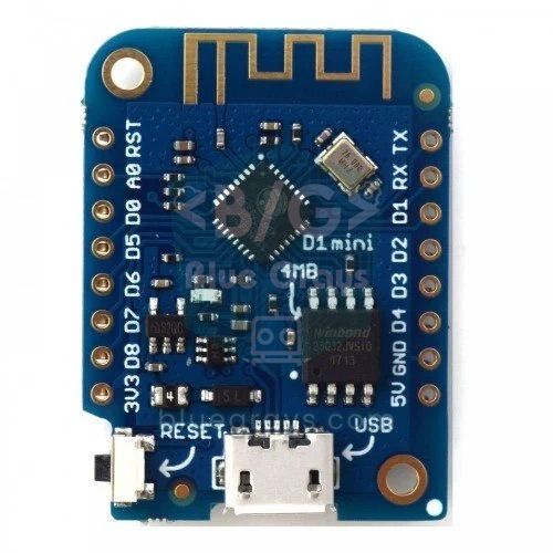
What is the Wemos D1 mini? Specifications
The D1 mini was designed by Wemos (now called LOLIN), and because its schematic is open, it has been cloned by many manufacturers. The metal-shielded ESP-12 module contains the ESP8266EX processor and 4 MB of flash, while the board adds a USB-to-serial converter, a regulator that drops 5 V to 3.3 V, and a RESET button. You'll mostly find the micro-USB v3 and the USB-C v4 versions; the pin layout is identical on all of them.
| Feature | Value |
|---|---|
| Chip | ESP8266EX, 32-bit, 80/160 MHz |
| Flash | 4 MB (D1 mini Pro: 16 MB) |
| RAM | 80 KB data RAM (about 40–50 KB available with Wi-Fi running) |
| Wi-Fi | 802.11 b/g/n, 2.4 GHz only |
| Digital pins | 11 (D0–D8, TX, RX) |
| Analog input | 1 (A0, 0–3.2 V, 10-bit) |
| Logic level | 3.3 V (powered from USB or the 5V pin) |
| USB-to-serial chip | Usually CH340 |
| Size | 34.2 × 25.6 mm |
Wemos D1 mini pinout: D0–D8 and their GPIO numbers
The most common mistake is writing the board label as a number in your code. If you write pinMode(4, OUTPUT) in the Arduino IDE, the board uses GPIO 4, which is D2, not D4. In your code, use either the label constants such as D4 (they're defined when D1 mini is selected as the board) or the GPIO number from the table. You can also look up your board's map in the Pinout tool.
| Label | GPIO | Special function | Usage note |
|---|---|---|---|
| TX | GPIO 1 | UART TX (Serial Monitor) | Outputs data at boot; leave unconnected if you use Serial |
| RX | GPIO 3 | UART RX | HIGH at boot; leave unconnected if you use Serial |
| D0 | GPIO 16 | Deep sleep wake-up (wired to RST) | No PWM, interrupts or I2C; HIGH at boot |
| D1 | GPIO 5 | I2C SCL | Safe; default pin of the relay shield |
| D2 | GPIO 4 | I2C SDA | Safe |
| D3 | GPIO 0 | FLASH, 10 kΩ pull-up | If LOW at boot, the board enters programming mode |
| D4 | GPIO 2 | Onboard LED (inverted), 10 kΩ pull-up | If LOW at boot, the board won't start; DHT shield pin |
| D5 | GPIO 14 | SPI SCK | Safe |
| D6 | GPIO 12 | SPI MISO | Safe |
| D7 | GPIO 13 | SPI MOSI | Safe |
| D8 | GPIO 15 | SPI CS, 10 kΩ pull-down | If HIGH at boot, the board won't start; SD shield CS pin |
| A0 | ADC0 | Analog input | 0–3.2 V; 220 kΩ / 100 kΩ divider on the board |
| RST | - | Reset (active LOW) | Connected to D0 for deep sleep |
| 3V3 | - | 3.3 V output | Power your sensors from here |
| 5V | - | USB 5 V / external 5 V input | Output when USB is plugged in, otherwise a supply input |
| G | - | GND | Common ground |
In short, the pins you can safely use for anything are D1, D2, D5, D6 and D7. D0 is fine for simple outputs and deep sleep wake-up, but it has no PWM or interrupt support. D3 and D4 work for buttons (as long as they aren't pressed at boot) and LEDs. Every pin except D0 has an internal pull-up resistor (INPUT_PULLUP); D0 only has an internal pull-down. In version 3.x of the ESP8266 core, analogWrite() defaults to a 0–255 range at 1 kHz. Each pin can supply roughly 12 mA at most, so use a transistor or a driver for relays, motors or long LED strips.
Setting up the Wemos D1 mini in the Arduino IDE
- Under File > Preferences, add http://arduino.esp8266.com/stable/package_esp8266com_index.json to "Additional boards manager URLs"; separate it from other URLs with a comma.
- Search for esp8266 in the Boards Manager and install the ESP8266 Community package.
- Pick LOLIN(WEMOS) D1 R2 & mini under Tools > Board > ESP8266 Boards.
- If no port shows up, install the CH340 driver and use a USB cable that carries data, not a charge-only one.
- If uploading at 921600 fails, lower Upload Speed to 115200.
First sketch: blinking the onboard LED
The small blue LED on the ESP-12 module is connected to GPIO 2 (D4) and works with inverted logic: it lights up when the pin is LOW and goes off when it's HIGH. LED_BUILTIN is defined as 2 for the D1 mini, so the code below runs without any changes:
1// D1 mini dahili LED: D4 = GPIO 2, LOW'da yanar / onboard LED: D4 = GPIO 2, lights on LOW
2void setup() {
3  pinMode(LED_BUILTIN, OUTPUT);     // LED_BUILTIN = 2 (D4)
4}
5
6void loop() {
7  digitalWrite(LED_BUILTIN, LOW);   // LED yanar (ters mantık) / LED on (inverted logic)
8  delay(500);
9  digitalWrite(LED_BUILTIN, HIGH);  // LED söner / LED off
10  delay(500);
11}The A0 analog input: the 3.2 V limit and measuring voltage
The ESP8266's only analog-to-digital converter (ADC) actually measures just 0–1.0 V at 10-bit resolution (0–1023). The D1 mini puts a 220 kΩ and 100 kΩ voltage divider behind the A0 pin: the voltage reaching the ADC is Vin × 100 / (220 + 100), so 3.2 V on A0 arrives at the chip as 1.0 V. That's why the formula for turning the raw value into volts is V = raw × 3.2 / 1023. To measure a higher voltage, add a series resistor in front of A0: with an extra 100 kΩ the top of the divider becomes 320 kΩ, and full scale rises to 1.0 × (320 + 100) / 100 = 4.2 V, which is exactly the voltage of a fully charged Li-ion cell. You can work out other ratios with the Voltage divider tool.
| Voltage on A0 | Reaching the chip | analogRead() (approx.) |
|---|---|---|
| 0 V | 0 V | 0 |
| 1.0 V | 0.31 V | 320 |
| 1.65 V | 0.52 V | 527 |
| 3.2 V | 1.0 V | 1023 |
| 3.3 V | 1.03 V | 1023 (saturated) |
1// A0: kartta 220k/100k bölücü, 0–3,2 V → 0–1023 / on-board 220k/100k divider, 0–3.2 V → 0–1023
2const float FULL_SCALE = 3.2;      // ek 100 kΩ seri dirençle 4.2 olur / 4.2 with an extra 100 kΩ in series
3
4void setup() {
5  Serial.begin(115200);
6}
7
8void loop() {
9  long sum = 0;
10  for (int i = 0; i < 16; i++) {   // 16 ölçümün ortalaması / average of 16 readings
11    sum += analogRead(A0);
12    delay(10);                     // Wi-Fi'ye zaman bırak / leave time for Wi-Fi
13  }
14  float raw = sum / 16.0;
15  float volts = raw * FULL_SCALE / 1023.0;
16  Serial.print("A0 ham / raw: ");
17  Serial.print(raw, 0);
18  Serial.print("  gerilim / voltage: ");
19  Serial.print(volts, 2);
20  Serial.println(" V");
21  delay(1000);
22}Wemos D1 mini shields: relay, DHT, OLED and more
The best thing about the D1 mini is that shields made in the same size plug straight onto the top or bottom of the board through female pin headers. No soldering or wiring needed; but since every shield uses a fixed pin, you have to make sure the shields you stack don't share pins. These are the most common shields and the pins they use:
| Shield | Pin used | Note |
|---|---|---|
| Relay shield | D1 (GPIO 5) | Contacts usually rated 10 A / 250 V AC; clashes with the I2C SCL pin |
| DHT shield (DHT11 or DHT22 Pro) | D4 (GPIO 2) | Same pin as the onboard LED; the sensor picks up heat from the board |
| SHT30 shield | D1, D2 (I2C) | More accurate than a DHT; I2C address 0x45 |
| 0.66" OLED shield | D1 (SCL), D2 (SDA) | 64×48 pixels, SSD1306 driver, address 0x3C |
| Micro SD shield | D5, D6, D7, D8 (CS) | SPI; D8 must stay LOW at boot |
| Battery shield | No pins | Charges a LiPo cell and powers the board through the 5V pin |
The table shows the biggest trap: the relay shield uses D1 by default, and that pin is also the I2C clock line. Stack the relay together with the OLED or SHT30 shield and neither works properly. Some relay shield versions let you move the pin with a solder jumper on the back; if yours doesn't, wire the relay to one of D5–D7 instead. If you plug the DHT shield straight onto the board, the ESP8266's heat makes it read 1–3 °C high; move the sensor away with a dual base or a short cable. The code below uses the DHT shield and the relay shield together as a simple fan thermostat:
1#include <DHT.h>
2
3const uint8_t DHT_PIN = 2;       // D4 = GPIO 2 (DHT shield)
4const uint8_t RELAY_PIN = 5;     // D1 = GPIO 5 (röle shield / relay shield)
5const float ON_ABOVE = 28.0;     // bunun üstünde fan açılır / fan on above this
6const float OFF_BELOW = 26.5;    // bunun altında kapanır (histerezis) / off below this (hysteresis)
7
8DHT dht(DHT_PIN, DHT11);         // DHT Pro shield için DHT22 / DHT22 for the DHT Pro shield
9bool fanOn = false;
10
11void setup() {
12  Serial.begin(115200);
13  pinMode(RELAY_PIN, OUTPUT);
14  digitalWrite(RELAY_PIN, LOW);  // röle kapalı başlasın / start with the relay off
15  dht.begin();
16}
17
18void loop() {
19  float t = dht.readTemperature();
20  if (!isnan(t)) {                                // hatalı ölçümü atla / skip failed readings
21    if (!fanOn && t > ON_ABOVE) fanOn = true;
22    if (fanOn && t < OFF_BELOW) fanOn = false;
23    digitalWrite(RELAY_PIN, fanOn ? HIGH : LOW);  // HIGH = röle çeker / HIGH = relay on
24    Serial.print(t, 1);
25    Serial.println(fanOn ? " C  fan ON" : " C  fan OFF");
26  }
27  delay(2000);
28}
The two thresholds in the code (on at 28 °C, off at 26.5 °C) create hysteresis: with a single threshold, the relay would click on and off every second as the temperature wobbled between 28.0 and 28.1, wearing out both the relay and the fan. For wiring a relay safely, see What Is a Relay Module?. The OLED shield is a tiny 64×48-pixel SSD1306 display; the standard Adafruit SSD1306 library doesn't support that size, so the U8g2 library is the easiest way to drive it. This example shows the voltage on A0 as a number and as a bar:
1#include <Wire.h>
2#include <U8g2lib.h>
3
4// 0,66" OLED shield: 64×48, I2C D1 (SCL) / D2 (SDA) / 0.66" OLED shield: 64×48, I2C on D1/D2
5U8G2_SSD1306_64X48_ER_F_HW_I2C oled(U8G2_R0, U8X8_PIN_NONE);
6
7void setup() {
8  oled.begin();
9}
10
11void loop() {
12  float volts = analogRead(A0) * 3.2 / 1023.0;      // A0 → volt
13  oled.clearBuffer();
14  oled.setFont(u8g2_font_6x10_tf);
15  oled.drawStr(0, 10, "D1 mini");
16  oled.setCursor(0, 28);
17  oled.print(volts, 2);
18  oled.print(" V");
19  oled.drawFrame(0, 36, 64, 10);                    // çubuk çerçevesi / bar frame
20  oled.drawBox(2, 38, (int)(volts / 3.2 * 60), 6);  // gerilim çubuğu / voltage bar
21  oled.sendBuffer();
22  delay(500);
23}
Deep sleep: the D0–RST link and running on batteries
In deep sleep the ESP8266 switches off the processor and Wi-Fi completely; only its internal RTC timer keeps running. When the time is up, the RTC pulls GPIO 16 (D0) LOW for a moment. If D0 is wired to the board's RST pin, that pulse resets the chip and your code starts again from setup(). Without the wire, the board never wakes up. Because waking up is a restart, normal variables are lost; you can keep small values such as a reading counter in the 512-byte RTC user memory. A single sleep can last up to about 3.5 hours; for longer periods, put the board back to sleep several times in a row.
| State | Approximate current |
|---|---|
| Sending data over Wi-Fi | 70–170 mA |
| Wi-Fi connected, idle (modem sleep) | 15–20 mA |
| Light sleep | About 1 mA |
| Deep sleep (ESP8266 chip only) | About 20 µA |
| Deep sleep (whole D1 mini board) | 80–200 µA (because of the regulator and USB-to-serial chip) |
1// D0 (GPIO 16) ile RST arasına kablo tak / wire D0 (GPIO 16) to RST
2const uint64_t SLEEP_US = 10ULL * 60 * 1000000;   // 10 dakika, mikrosaniye / 10 minutes in µs
3
4void setup() {
5  Serial.begin(115200);
6  delay(100);
7  float volts = analogRead(A0) * 3.2 / 1023.0;     // ölç / measure
8  Serial.print("A0: ");
9  Serial.print(volts, 2);
10  Serial.println(" V");
11  // Wi-Fi ile gönderim burada yapılır / send the reading over Wi-Fi here
12  Serial.println("10 dk uyku / sleeping 10 min");
13  ESP.deepSleep(SLEEP_US);                         // uyanınca setup() baştan başlar / wakes up into setup()
14}
15
16void loop() {
17  // buraya hiç gelinmez / never reached
18}
You can estimate battery life with a rough calculation. Say the board wakes every 10 minutes, draws an average of 80 mA for 5 seconds while it sends data, and sleeps at 0.15 mA for the remaining 595 seconds. Each cycle uses 5 × 80 = 400 mAs plus 595 × 0.15 ≈ 89 mAs; that's 489 mAs in total, or an average of 0.82 mA over 600 seconds. A 2000 mAh 18650 cell then lasts 2000 / 0.82 ≈ 2440 hours, or roughly 100 days. Use the Battery life tool to run the numbers for your own setup, and see ESP32 Deep Sleep for the ESP32 version of the same topic.
Wemos D1 mini, NodeMCU or D1 mini ESP32?
| Board | Chip | Stand-out feature | When to choose it |
|---|---|---|---|
| Wemos D1 mini | ESP8266 | Very small, shield system | Small Wi-Fi sensors, projects with shields |
| NodeMCU V3 | ESP8266 | Bigger, labelled pins | Comfortable breadboard prototyping |
| D1 mini ESP32 (MiniKit) | ESP32-WROOM-32 | D1 mini layout + an extra inner pin row | Bluetooth, more ADC channels and more memory |
| LOLIN S2 mini / C3 mini | ESP32-S2 / ESP32-C3 | D1 mini size and shield-compatible | Native USB (S2), BLE and low power (C3) |
On the D1 mini ESP32 boards, the outer pin rows match D1 mini shields, so you can plug in the relay or OLED shield as they are. The D labels map to different GPIOs on the ESP32, though; the I2C pins, for example, are D1 = GPIO 22 and D2 = GPIO 21. In your code, use WiFi.h instead of ESP8266WiFi.h and change the pin numbers to match the board's map. The ESP32 version reads analog values at 12 bits (0–4095), has Bluetooth and far more memory. If you're not sure which to pick, compare What Is the ESP32? with NodeMCU ESP8266.
Wemos D1 mini project ideas
- Battery-powered Wi-Fi thermometer: Use an SHT30 or DHT shield, the battery shield and deep sleep to send a reading every 10 minutes.
- Smart plug: Switch a lamp from your phone with the relay shield; read the relay module guide for safe wiring.
- LED strip controller: Flash WLED and control a WS2812B strip from your phone.
- Door sensor: Send a notification when the door opens using a reed switch.
- Mini desk display: Show the time, the weather or small graphs on the OLED shield, just like on a bigger OLED display.
- Smart home sensor: Send the values to Home Assistant over MQTT.
Common mistakes and fixes
| Symptom | Likely cause | Fix |
|---|---|---|
| No port shows up | Missing CH340 driver or a charge-only cable | Install the driver, use a data cable |
| The wrong pin reacts | The code says 4 instead of D4 | Use the D constants or the GPIO number from the table |
| Board won't boot, code doesn't run | A circuit on D3, D4 or D8 upsets the boot level | Move the circuit to safe pins (D1, D2, D5–D7) |
| Wi-Fi keeps dropping | analogRead() called non-stop, or weak power | Add a pause between readings, use a good 5 V supply |
| Never wakes from deep sleep | D0 isn't connected to RST | Link D0 to RST with a wire, resistor or diode |
| Relay and OLED won't work together | Both use D1 | Change the relay pin or wire it to another pin |
| LED works backwards | The onboard LED lights on LOW | Invert the logic: LOW = on, HIGH = off |
With its tiny size, shield system and Wi-Fi, the Wemos D1 mini is one of the easiest ways into home automation and sensor projects. As long as you keep the pin table and the boot rules in mind, almost any ESP8266 example will run without trouble. In the BlueGrays app you'll find step-by-step wiring diagrams and code in the ESP projects (LED blink, Wi-Fi connection, web server, OTA and deep sleep), and you can try them on the D1 mini too by adapting the pin numbers with this table.
Frequently asked questions
Which GPIO is D4 on the Wemos D1 mini?
D4 is GPIO 2, and the board's blue onboard LED is connected to it. You can write pinMode(D4, OUTPUT) or pinMode(2, OUTPUT) in your code, whereas pinMode(4, OUTPUT) selects D2. The LED uses inverted logic, so it lights up on LOW.
Can the Wemos D1 mini run on 5 V?
The board can be powered with 5 V from USB or the 5V pin; the on-board regulator drops it to 3.3 V. The GPIO pins, however, use 3.3 V logic, so instead of connecting sensors with 5 V outputs directly, use a voltage divider or a logic level shifter.
What voltage can the Wemos D1 mini A0 pin read?
Thanks to the 220 kΩ / 100 kΩ divider on the board, the A0 pin reads 0–3.2 V as 0–1023. The bare ESP8266 chip can only measure 0–1.0 V. Add an extra 100 kΩ resistor in series in front of A0 and the range goes up to 4.2 V, enough to read a Li-ion battery.
Why won't my Wemos D1 mini wake up from deep sleep?
The ESP8266 needs the reset pulse that the RTC sends out on D0 (GPIO 16) to wake up. Unless you connect D0 to RST with a wire, a 470 Ω–1 kΩ resistor or a Schottky diode, the board stays asleep. Also check that you passed the sleep time in microseconds.
What's the difference between the Wemos D1 mini and the NodeMCU?
Both use the same ESP8266 chip, and their D0–D8 labels map to the same GPIOs, so sketches run on either without changes. The D1 mini is much smaller and supports stackable shields, while the NodeMCU is bigger and more comfortable on a breadboard.
Does the Wemos D1 mini have Bluetooth?
No, the ESP8266 only supports Wi-Fi. If you need Bluetooth, use a D1 mini ESP32 or the ESP32-C3-based LOLIN C3 mini, which have the same footprint and also work with D1 mini shields.
Projects to build after reading this
See all projects
LED Blink with ESP32
Teaches basic GPIO output usage with ESP32. We achieve a blinking effect by turning an LED on and off from a digital pin. ESP32 version of the classic blink project on Arduino UNO; the basic blink commands in the Arduino environment are the same, but the ESP32's pin layout and 3.3 V GPIO levels differ from those of the Arduino UNO.

ESP32 Built-in LED Blink
Blinking the built-in blue LED on the ESP32 DevKit V1. No external components required! The first project you should try when you buy an ESP32. GPIO 2 is connected to the built-in LED.

ESP32 Wi-Fi STA Connection (with LCD Screen)
In this project, we connect the ESP32 to the home Wi-Fi network in Station (STA) mode in a secure, fault-tolerant manner. We store the SSID and password in a separate secrets.h file to prevent leaking to Git, set up an auto-reconnect mechanism, and display the RSSI signal level and IP address on an I2C LCD screen. The internal LED works as a status indicator. It is a production-grade connection manager.

ESP32 Asynchronous Web Server (with IP Display on LCD)
In this project, we’re turning the ESP32 into an asynchronous web server that you can control from your phone or computer on the same Wi-Fi network. Thanks to the ESPAsyncWebServer library, the server can process multiple requests simultaneously (unlike the classic WebServer.h, which blocks on a single request). You’ll be able to open the ESP32’s IP address in a browser and click the ON/OFF buttons (the /on and /off routes) to turn the LED connected to GPIO 5 on and off.

ESP32 Deep Sleep — Battery Saving (OLED + RTC RAM Counter)
The ESP32's Deep Sleep mode shuts down the CPU and most peripherals, cutting current draw to about 10µA, which is vital for battery-powered IoT devices. This project uses three wake-up sources: a timer (15 s), an external pin (EXT0, the button on GPIO 33) and a touch pin (T0/GPIO 4). Counters marked with RTC_DATA_ATTR survive deep sleep.

ESP32 OTA Update — Wireless Firmware Installation (With LCD Screen)
In this project you'll learn to upload new firmware to the ESP32 over Wi-Fi, without a USB cable. With the ArduinoOTA library the ESP32 becomes visible on the network and shows up automatically as bluegrays-ota under "Network port" in the Arduino IDE. The first upload goes over USB; after that every update is wireless, a key feature for devices out in the field.

ESP32 mDNS: Accessing the Device via bluegrays-esp.local (with LCD Screen)
In this project we add an mDNS (Multicast DNS) service to the ESP32, so you reach it by a readable host name like bluegrays-esp.local instead of an IP address. Even if the IP assigned by DHCP changes, the device always answers to the same name. A small web server on the board lets you control the LED from your browser at http://bluegrays-esp.local/.

ESP32 Smart Lighting (PIR + LDR + Relay + OLED)
With an ESP32, a PIR motion sensor, an LDR light sensor and a relay module, we turn your hallway, bathroom or pantry into smart lighting. If the room is already bright, the light stays off even when there is motion, so it never wastes energy during the day. The light stays on for 30 seconds, and the time extends automatically while motion continues.