
Capacitive Soil Moisture Sensor Arduino: Calibration and Code
How to use a capacitive soil moisture sensor v1.2 with Arduino: vs resistive, the TLC555/NE555 3.3 V issue, dry-wet calibration, percentage table, ESP32, Pico.

A capacitive soil moisture sensor is a module that measures how wet the soil in a pot or garden is without any metal electrode touching the soil. That's why it doesn't suffer from the problem of classic fork-type resistive probes, which corrode and fail within a few weeks, and in automatic watering projects with Arduino it can last for months or even years. It's usually labelled "Capacitive Soil Moisture Sensor v1.2" or v2.0, gives a single analog output and connects to an Arduino Uno, ESP32 or Raspberry Pi Pico with three wires.
These cheap modules do have important pitfalls, though: some boards use the wrong 555 chip and won't work at 3.3 V, others are missing a resistor connection, and the cut edges soak up water and make the readings drift within weeks. In this guide you'll learn how the sensor works, how it differs from a resistive one, how to recognise a good board, how to calibrate it dry and wet and how to turn the analog value into a moisture percentage. After that come automatic watering with an Uno, a battery-powered plant monitor with an ESP32 and MicroPython code for the Pico.
How does a capacitive soil moisture sensor work?
The wide copper area at the tip of the sensor and the GND surface around it act like the two plates of a capacitor, and the insulator between them is the soil itself. Water has a dielectric constant of about 80, dry soil 3–5 and air 1, so the wetter the soil, the higher the capacitance. The 555 chip at the top generates a square wave of about 1.5 MHz that charges and discharges the probe through a resistor, then a diode and a small filter turn the signal into a DC voltage. As capacitance rises, the amplitude of the wave at the probe falls, so the output voltage is high in dry soil and low in wet soil. Because the electrodes are covered by solder mask, no current flows through the soil. You can experiment with how the 555 works in the 555 timer tool.
| Feature | Value |
|---|---|
| Supply | 3.3–5.5 V (on boards with a TLC555) |
| Output | Analog, about 1.2–3.0 V; high when dry, low when wet |
| Current | About 5 mA |
| Connector | 3-pin PH2.0: GND, VCC, AOUT |
| Size | About 98 × 23 mm |
| Oscillator | TLC555 (CMOS), about 1.5 MHz; NE555 on copies |
| Regulator | XC6206 marked 662K, 3.3 V |
| Electrodes | Copper insulated by solder mask; no current flows through the soil |
How it differs from a resistive sensor: no corrosion
Resistive sensors (YL-69, FC-28) pass current between two bare metal prongs pushed into the soil and measure its resistance. In wet soil that DC current causes electrolysis: the metal on the positive prong dissolves, with continuous power the plating is gone within a few weeks and the readings keep drifting. The reading also depends more on salts and fertiliser than on water; on the day you feed your plants, the soil looks wet. A capacitive sensor measures the dielectric effect of the water instead, so salts affect it far less, and because no metal is exposed it doesn't corrode. We covered the resistive sensor in soil moisture sensor.
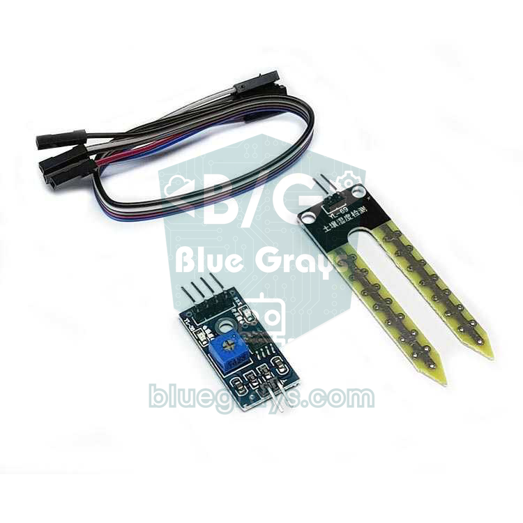
| Feature | Resistive (YL-69, FC-28) | Capacitive v1.2 |
|---|---|---|
| Measuring method | Electrical resistance of the soil | Capacitance (dielectric constant) |
| Electrodes | Bare nickel-plated metal | Copper insulated by solder mask |
| Corrosion | Within a few weeks under continuous power | None (unless the mask is scratched) |
| Effect of fertiliser and salts | Large | Small |
| Output | AO and DO (LM393 comparator) | Analog only (AOUT) |
| Works at 3.3 V | Yes | Only on boards with a TLC555 |
| Lifespan | Months | Years, if the edges are protected |
Versions v1.2 and v2.0: TLC555, NE555 and the 3.3 V problem
The version number printed on the board is no guarantee; what matters is the marking on the eight-pin chip. Good boards carry a CMOS TLC555, which runs happily down to 2 V. Some cheap copies use the classic NE555 instead, which needs at least 4.5 V; on the 3.3 V of an ESP32 or Pico the output doesn't change or sticks at a meaningless value. The second thing to check is the small regulator marked 662K: if it's missing or bridged, the output can exceed 3 V on a 5 V supply. On some batches the GND connection of the 1 MΩ discharge resistor on the output is missing; on those boards the change from dry to wet takes minutes or the value stays high. Finally, the bare fibreglass on the cut edges soaks up water over time and makes the readings drift.
| Check | Good board | Problem board | Symptom |
|---|---|---|---|
| 555 chip | TLC555 (CMOS) | NE555 or SA555 | At 3.3 V the output doesn't change or stays fixed |
| Regulator | Small 3-pin chip marked 662K | Missing or bridged | At 5 V the output can exceed 3 V |
| 1 MΩ output resistor | Connected to GND | GND connection missing | Very slow response, value always high |
| Board edges | Coated with varnish or epoxy | Bare fibreglass | Readings drift within weeks |
Wiring: Arduino Uno, ESP32 and Raspberry Pi Pico
| Sensor pin | Arduino Uno | ESP32 | Raspberry Pi Pico |
|---|---|---|---|
| GND (black) | GND | GND | GND |
| VCC (red) | 5V | GPIO 25 (3.3 V only while measuring) | GP22 (3.3 V only while measuring) |
| AOUT (yellow) | A0 | GPIO 34 (ADC1) | GP26 (ADC0) |
| Relay IN (pump in the Uno example) | D7 | — | — |
In the ESP32 and Pico examples, the sensor's VCC goes to a GPIO rather than straight to the 3V3 pin. Because the sensor only draws 5 mA, a pin can power it easily; that way the sensor switches off completely between readings and the battery lasts longer. On the ESP32, use ADC1 pins (GPIO 32–39), which keep working with Wi-Fi on, for the analog reading. On the Uno the sensor runs from 5V, but thanks to the regulator on the board the output still stays around 3 V; that's why the Uno only uses roughly 250–600 of its 10-bit range.
Calibration: finding the dry and wet values
- Upload the Uno code below without the pump connected and open the Serial Monitor at 9600 baud.
- Hold the sensor dry and clean in the air; after a few seconds note the settled raw value as DRY_VALUE (usually 520–600 on the Uno).
- Dip the sensor into a glass of water without going past the line on the board and note the reading as WET_VALUE (usually 250–300).
- For a more realistic result, take a second set of readings: use the values from completely dry potting soil and from the same soil after a thorough watering and 30 minutes of draining.
- Upload the code again; the Serial Monitor now shows a moisture percentage from 0 to 100. Every sensor gives slightly different values, so calibrate each one separately.
| Raw value (Uno, example calibration) | Moisture | Soil condition | What to do |
|---|---|---|---|
| 590 and above | 0 % | Air or bone-dry soil | Check the sensor is seated properly in the soil |
| 510 | 25 % | Dry | Time to water for most plants |
| 430 | 50 % | Slightly moist | Ideal range; no watering needed |
| 350 | 75 % | Moist | Freshly watered soil |
| 270 and below | 100 % | Water or mud | Too much water; risk of root rot |
The percentages in the table are calculated with % = (590 − raw) × 100 / (590 − 270) for DRY_VALUE = 590 and WET_VALUE = 270. This isn't a laboratory measurement but a relative value between the two calibration points: "50 %" doesn't mean that half the soil's volume is water. The sensor's response isn't perfectly linear either, but it's more than good enough for deciding when to water. Soil compaction, temperature and soil type also shift the reading by a few points; after pushing the sensor in, press the soil gently around it to close any air gaps. We explain analog reading in detail in What Is an ADC?.
Arduino Uno code: moisture percentage and automatic watering
The code below reads the sensor 10 times and averages the result, converts the value to a percentage and prints it to the Serial Monitor. When moisture drops below 35 %, watering starts and continues until moisture rises above 60 %; the gap between these two thresholds (hysteresis) stops the pump from switching on and off constantly. Watering isn't done in one go but in 4-second doses, with a 1-minute wait after each dose so the water can spread through the soil. Because the sensor notices the water a few seconds late, running the pump continuously would flood the pot.
1const byte SENSOR_PIN = A0;          // sensör AOUT / sensor AOUT
2const byte PUMP_PIN = 7;             // röle IN (pompa) / relay IN (pump)
3const byte RELAY_ON = HIGH;          // röle LOW ile çekiyorsa LOW yap / use LOW for active-low relays
4const int DRY_VALUE = 590;           // kuru: havada ya da kuru toprakta / dry: in air or dry soil
5const int WET_VALUE = 270;           // ıslak: suda ya da yeni sulanmış toprakta / wet: in water or just-watered soil
6const byte START_PCT = 35;           // bunun altında sulamaya başla / start watering below this
7const byte STOP_PCT = 60;            // bunun üstünde sulamayı bitir / stop watering above this
8const unsigned long PUMP_MS = 4000;  // tek seferde en fazla pompa süresi / max pump time per pulse
9const unsigned long SOAK_MS = 60000; // suyun toprağa yayılması için bekle / let the water spread
10
11bool watering = false;
12
13int readAverage() {                  // 10 okumanın ortalaması / average of 10 readings
14  long sum = 0;
15  for (byte i = 0; i < 10; i++) {
16    sum += analogRead(SENSOR_PIN);
17    delay(10);
18  }
19  return sum / 10;
20}
21
22int toPercent(int raw) {             // ham değeri yüzdeye çevir / raw value to percent
23  long pct = (long)(DRY_VALUE - raw) * 100 / (DRY_VALUE - WET_VALUE);
24  return constrain(pct, 0, 100);
25}
26
27void setup() {
28  Serial.begin(9600);
29  pinMode(PUMP_PIN, OUTPUT);
30  digitalWrite(PUMP_PIN, !RELAY_ON);   // pompa kapalı başlasın / start with the pump off
31}
32
33void loop() {
34  int raw = readAverage();
35  int pct = toPercent(raw);
36  Serial.print(F("Ham / raw: "));
37  Serial.print(raw);
38  Serial.print(F("   Nem / moisture: %"));
39  Serial.println(pct);
40
41  if (!watering && pct < START_PCT) watering = true;    // histerezis / hysteresis
42  if (watering && pct >= STOP_PCT) watering = false;
43
44  if (watering) {
45    digitalWrite(PUMP_PIN, RELAY_ON);  // kısa bir doz su ver / give a short dose of water
46    delay(PUMP_MS);
47    digitalWrite(PUMP_PIN, !RELAY_ON);
48    delay(SOAK_MS);                    // tekrar ölçmeden önce bekle / wait before measuring again
49  } else {
50    delay(2000);
51  }
52}
Never connect the pump straight to an Arduino pin; power it from a separate 5 V supply through a relay module or a MOSFET and join the grounds. Some relay modules switch on with a LOW signal; if yours does, change the RELAY_ON constant in the code to LOW. For choosing the pump and connecting the tubing, see the mini water pump article. Adding a water level sensor to detect an empty reservoir stops the pump from running dry and burning out.
Battery-powered plant moisture monitor with an ESP32
The ESP32's deep sleep mode makes it possible to run the sensor on batteries for months. When it wakes up, the code below switches the sensor on through GPIO 25, waits 1 second for the output to settle, averages 16 readings, switches the sensor off and prints the result. If the soil is below 30 %, the onboard LED blinks three times; then the ESP32 sleeps for 30 minutes. The counter marked RTC_DATA_ATTR survives deep sleep. Because the ESP32's ADC is 12-bit, the calibration values are in the 0–4095 range and differ from the Uno's; measure them again with your own sensor.
1const int SENSOR_PIN = 34;           // AOUT, ADC1 pini / ADC1 pin
2const int SENSOR_POWER_PIN = 25;     // sensörün VCC'si / sensor VCC
3const int LED_PIN = 2;               // dahili LED: kuru uyarısı / onboard LED: dry warning
4const int DRY_VALUE = 3100;          // 12 bit, havada / 12-bit, in air
5const int WET_VALUE = 1350;          // 12 bit, suda / 12-bit, in water
6const uint64_t SLEEP_MIN = 30;       // ölçüm aralığı (dakika) / interval (minutes)
7
8RTC_DATA_ATTR int bootCount = 0;     // derin uykuda korunur / kept through deep sleep
9
10void setup() {
11  Serial.begin(115200);
12  bootCount++;
13  pinMode(SENSOR_POWER_PIN, OUTPUT);
14  pinMode(LED_PIN, OUTPUT);
15
16  digitalWrite(SENSOR_POWER_PIN, HIGH);        // sensörü aç / power the sensor
17  delay(1000);                                 // çıkış otursun / let the output settle
18  long sum = 0;
19  for (int i = 0; i < 16; i++) sum += analogRead(SENSOR_PIN);
20  digitalWrite(SENSOR_POWER_PIN, LOW);         // sensörü kapat / switch it off
21  int raw = sum / 16;
22  int pct = constrain(map(raw, DRY_VALUE, WET_VALUE, 0, 100), 0, 100);
23  Serial.printf("#%d raw %d moisture %d%%\n", bootCount, raw, pct);
24
25  if (pct < 30) {                              // kuruysa 3 kez yanıp sön / blink 3 times if dry
26    for (int i = 0; i < 3; i++) {
27      digitalWrite(LED_PIN, HIGH);
28      delay(200);
29      digitalWrite(LED_PIN, LOW);
30      delay(200);
31    }
32  }
33  esp_sleep_enable_timer_wakeup(SLEEP_MIN * 60ULL * 1000000ULL);   // mikrosaniye / microseconds
34  esp_deep_sleep_start();                      // 30 dk uyu / sleep for 30 min
35}
36
37void loop() {
38}
Let's roughly estimate battery life: on each wake-up the ESP32 draws 40–50 mA for about 1.5 seconds; waking every 30 minutes, that averages only 50 × 1.5 / 1800 ≈ 0.04 mA. What really matters is the sleep current: an ordinary DevKit, with its USB-serial chip and regulator, draws several mA even while asleep and drains a 2000 mAh battery in two or three weeks. With a bare ESP32 module and a low-loss regulator, the sleep current drops to tens of microamps and the battery lasts for months. Work out your own circuit with the battery life calculator; details are in ESP32 deep sleep.
Capacitive sensor with Raspberry Pi Pico (MicroPython)
On the Raspberry Pi Pico, connect the sensor's AOUT to GP26, which is ADC0, and its VCC to GP22. In MicroPython, read_u16() returns values from 0 to 65535; in air you'll see roughly 50000–53000 and in water around 22000–26000. Because the Pico's ADC uses a 3.3 V reference, the output of a regulated sensor fits the range comfortably. The code takes a reading every 10 seconds and classifies the soil as dry, ok or wet.
1from machine import ADC, Pin
2import time
3
4sensor = ADC(26)                  # GP26 = ADC0, sensör AOUT / sensor AOUT
5power = Pin(22, Pin.OUT)          # sensörün VCC'si / sensor VCC
6DRY = 52000                       # havada okunan (16 bit) / reading in air (16-bit)
7WET = 24000                       # suda okunan (16 bit) / reading in water (16-bit)
8
9def read_moisture():
10    power.value(1)                # sensörü aç / power on
11    time.sleep(1)                 # çıkış otursun / let the output settle
12    total = 0
13    for _ in range(16):
14        total += sensor.read_u16()
15        time.sleep_ms(5)
16    power.value(0)                # sensörü kapat / power off
17    raw = total // 16
18    pct = (DRY - raw) * 100 // (DRY - WET)
19    return raw, max(0, min(100, pct))
20
21while True:
22    raw, pct = read_moisture()
23    state = "dry" if pct < 30 else ("ok" if pct < 80 else "wet")
24    print("raw:", raw, "moisture %:", pct, state)
25    time.sleep(10)
Waterproofing: protecting the edges and placing the sensor
- Coat the edges: the bare fibreglass on the board's cut edges soaks up water and makes the readings drift within weeks. Coat the edges of the probe with nail varnish, clear lacquer or a thin layer of epoxy.
- Protect the electronics: cover the top area with the 555 chip, regulator and connector with heat-shrink tubing, hot glue or epoxy to keep rain and watering water off it.
- Don't go past the line: the white line on the board marks the deepest point that may go into the soil; the electronics must always stay above the soil.
- Push it in straight and firm: insert the sensor vertically and press the soil gently around it; air gaps make the soil look drier than it is.
- Keep the position fixed: place the sensor 1–2 cm from the pot wall in the root zone, not right under the watering tube. If you move it, calibrate again.
- Don't scratch the mask: forcing it into hard soil scratches the protective solder mask, and exposed copper corrodes on a capacitive sensor too. If necessary, make a hole with a stick first.
Project ideas
- Automatic pot watering: water your plants while you're on holiday with the Uno code, a relay and a mini pump.
- Smart greenhouse: combine soil moisture with air temperature and humidity in a smart greenhouse that runs a fan and a pump.
- Phone alert: have the ESP32 send a message through a Telegram bot when the soil dries out.
- Moisture chart: log the readings to Google Sheets and see on a chart how long your plant takes to dry out.
- Plant display: show the moisture percentage as a bar on an OLED display.
- Skip watering when it rains: in garden watering, don't run the pump when a rain sensor detects rain.
Common mistakes and how to fix them
| Symptom | Likely cause | Fix |
|---|---|---|
| The value never changes on an ESP32 or Pico | The board has an NE555, and 3.3 V isn't enough | Check the chip; use a board with a TLC555 or replace the NE555 with a TLC555 |
| The value takes minutes to go from dry to wet | The 1 MΩ discharge resistor isn't connected to GND | Connect the resistor's free end to GND with a thin wire |
| The reading drifts slowly over a few weeks | The edges soak up water or the electronics get wet | Coat the edges and top with varnish, epoxy or heat-shrink and recalibrate |
| The percentage goes below zero or above 100 | Calibration values are wrong or swapped | DRY_VALUE must be the dry value (larger) and WET_VALUE the wet value (smaller) |
| The values keep jumping | Long cable, noise or loose soil | Average the readings, keep the cable short and press the soil around the sensor |
| The Arduino resets when the pump starts | The pump is powered from the Arduino's 5V line | Power the pump from a separate supply and join the grounds |
| ESP32 readings go wrong when Wi-Fi switches on | The sensor is on an ADC2 pin | Move AOUT to an ADC1 pin between GPIO 32 and 39 |
If you choose the right board and protect its edges, the capacitive soil moisture sensor is the most reliable part of any plant or garden project. Check the chip first, then calibrate in your own soil and water with hysteresis in short doses. In the BlueGrays app you'll find a smart watering station with Arduino, along with temperature and humidity measurement, each with step-by-step circuit diagrams and ready-to-use code.
Frequently asked questions
What is the difference between capacitive and resistive soil moisture sensors?
A resistive sensor passes current between two bare metal prongs pushed into the soil, and electrolysis corrodes those prongs within a few weeks. A capacitive sensor measures the soil's capacitance with insulated electrodes, passes no current and doesn't corrode. It's also much less affected by fertiliser and salts.
Does the capacitive soil moisture sensor work with 3.3 V?
Boards with a TLC555 chip work fine at 3.3 V and can be connected straight to an ESP32 or Pico. Copies with an NE555 need at least 4.5 V, and at 3.3 V the output doesn't change. You can tell which one you have from the marking on the eight-pin chip on the board.
How do you calibrate a capacitive soil moisture sensor?
Hold the sensor in air or in bone-dry soil and note the reading as the dry value, then put it in water or freshly watered soil and note the reading as the wet value. The percentage is calculated with % = (dry − raw) × 100 / (dry − wet). Every sensor gives different values, so calibrate each one.
What moisture percentage should soil have?
The percentage from this sensor is relative to its own calibration points. For most potted plants, 40–70 % is a good range; it makes sense to water when it falls below 25–30 % and stop above 80 %. Use a lower threshold for succulents and cacti.
Is the capacitive soil moisture sensor waterproof?
The sensing probe is water-resistant, but the board's cut edges and the electronics at the top aren't. Coat the edges with varnish or epoxy and the top with heat-shrink or hot glue and the sensor will last for years. Don't push it deeper than the line marked on the board.
Why does my sensor reading change so slowly?
On some copy boards the 1 MΩ resistor on the output isn't connected to GND, so the output capacitor can't discharge. The change from dry to wet then takes minutes. Connecting the resistor's free end to GND with a thin wire fixes the problem.
Projects to build after reading this
See all projects
Smart Irrigation Station
A gardener that waters your plants on its own, so they don't dry out while you're on vacation.
Temperature and Humidity with DHT11
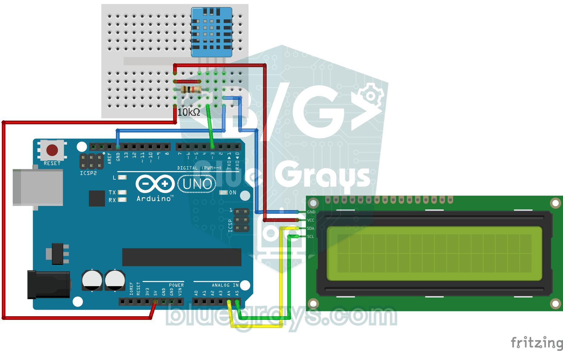
How warm is your room, and is the air humid or dry? The DHT11 sensor measures temperature and humidity, and the Arduino writes the values on a two-line LCD screen, refreshing every couple of seconds.

Measuring Light Intensity with an LDR
Want to see how bright your room is as a number? The LDR, a small part that reacts to light, measures the light around it, and the Arduino writes the value to your computer screen every half second.

Reading Light Intensity with the ESP32 LDR Module
Real-time monitoring of the LDR module's raw ADC value and relative light percentage calculated from dark and light reference values in the Serial Monitor. This percentage is not a lux measurement. Teaches the module’s calibration logic. It is ideal to complete this before Project 10, as it is used to determine the threshold value.

ESP32 DHT22 Temperature and Humidity (with LCD Display)
This project measures ambient temperature and humidity using a DHT22 sensor and displays the data in real time on a 16x2 I2C LCD. Data is read from the sensor using the one-wire protocol via the Adafruit DHT library. This project serves as the foundation for IoT weather stations, smart home automation, or environmental monitoring systems in greenhouses. Communication with the DHT22 is established via the ESP32's GPIO 4 pin.
ESP32 Temperature Data Logger (DHT22 + DS1307 RTC + microSD + OLED)
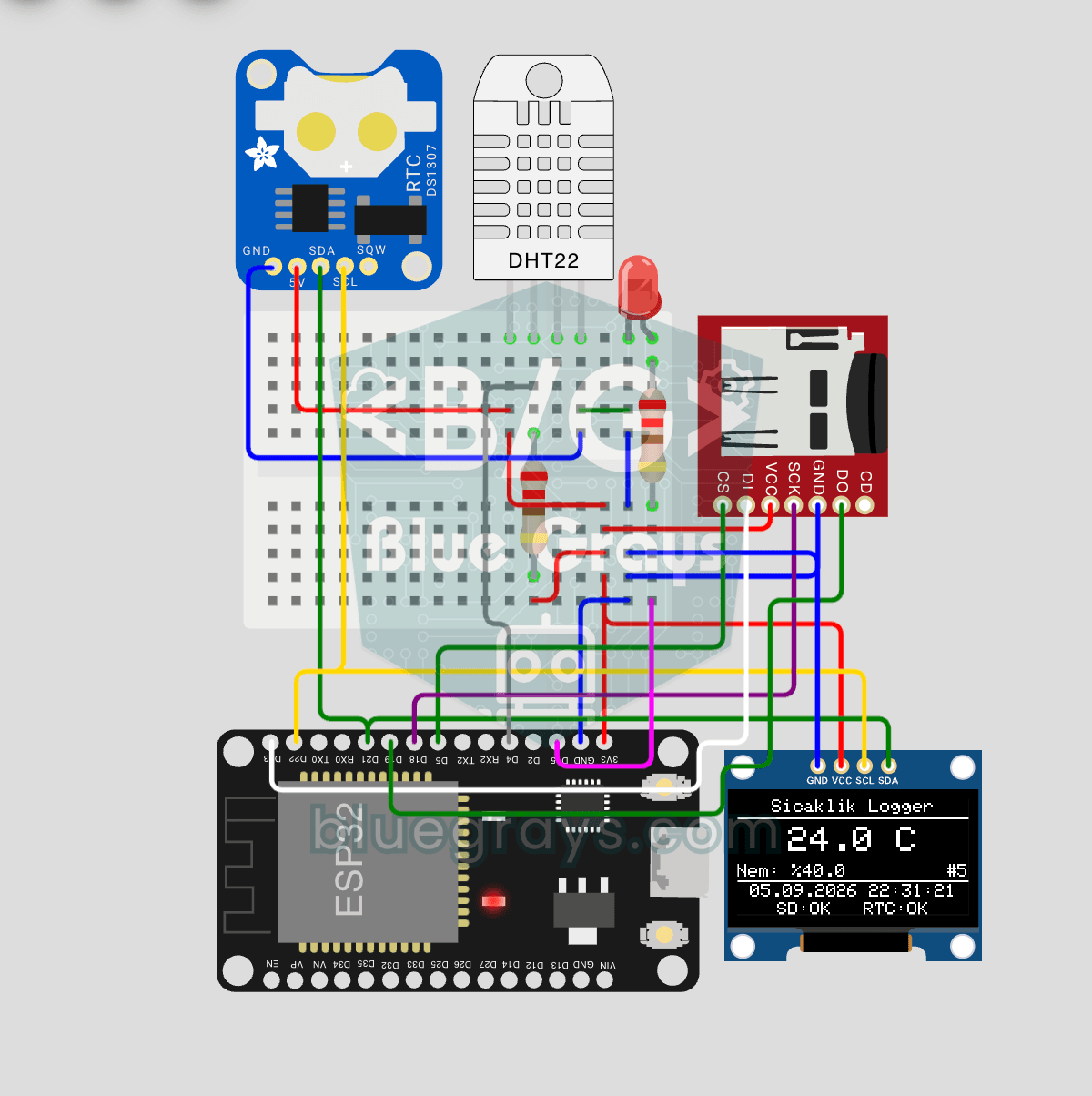
Build a timed temperature and humidity logger with the ESP32! A DHT22 sensor reads temperature and humidity once a minute, and each reading is saved to a microSD card in CSV format with a real-time stamp from the DS1307 RTC module. The OLED display shows the latest temperature, humidity, timestamp and total number of records live, in large text.

ESP32 LED Brightness Control with a Potentiometer (Analog → PWM)
In this project, we control the brightness of an LED analogically using a potentiometer. The ESP32's ADC pin reads the 0-3.3V voltage from the potentiometer, and this value is then converted into a PWM (Pulse Width Modulation) signal and sent to the LED. As a result, as you turn the potentiometer, the LED gradually brightens and dims. With Arduino Core 3.0+, analogWrite() can be used directly; on the ESP32-S2/S3, the ADC resolution is fixed at 12-bit.