
Non-Contact Liquid Level Sensor XKC-Y25: Arduino Wiring and Code
Non-contact liquid level sensor XKC-Y25: capacitive sensing, wall thickness, NPN/PNP output and MODE wire, 5–24 V, Arduino wiring and multi-level pump control.

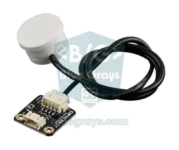
A non-contact liquid level sensor detects whether liquid has reached a certain height without putting any part inside the tank: you simply stick it to the outside of a plastic or glass wall. The most common and cheapest example is the XKC-Y25: a small disc 28 mm across with a white plastic body and four wires. Because it never touches the liquid, it does not rust, does not scale up, does not contaminate drinking water and works for years even with liquids that are hard to clean, such as acid, coffee or milk. It is the cleanest solution to the problem of the fork-shaped water level sensors in Arduino kits corroding within a few weeks.
In this guide you will learn how the XKC-Y25 senses the liquid behind the wall capacitively, and which materials and wall thicknesses it works through. We will look in detail at the difference between the voltage-output, NPN and PNP versions, the wire colours and the black MODE wire that sets the output logic. Then we will connect the sensor to an Arduino Uno and write a first sketch, and build a system that splits the tank into percentage levels with three sensors and runs the pump automatically. A comparison with a float switch, coffee machine and aquarium applications, and ESP32 and Raspberry Pi Pico code close the article.
What is a non-contact liquid level sensor and how does it work?
The XKC-Y25 is a capacitive sensor. The front face of its housing holds an electrode, and together with its surroundings this electrode forms a small capacitor. With only air behind the wall, this capacitance has a certain value. When the liquid rises to the sensor's height, the liquid becomes part of the capacitor and the capacitance increases. Water has a dielectric constant of about 80 and air about 1, so the change in capacitance is very clear when water arrives. The chip inside the sensor measures this change continuously and switches its output when a set threshold is crossed. Because the electric field can pass through insulating materials such as plastic, glass and ceramic, the sensor works without touching the liquid; metal, however, shields the field, so a metal tank cannot be measured from outside. These are the manufacturer's figures for the XKC-Y25-V and XKC-Y25-T12V versions that sellers offer most:
| Feature | XKC-Y25 (voltage-output version) |
|---|---|
| Supply voltage | 5–24 V DC |
| Current draw | About 5 mA |
| Output | High level = supply voltage, low level = 0 V |
| Output current | 1–50 mA |
| Response time | About 500 ms |
| Sensing wall thickness | 0–20 mm (up to 12 mm recommended for reliable operation) |
| Operating temperature | 0–100 °C |
| Protection | IP67, ABS housing |
| Size | 28 mm diameter, about 17 mm deep |
| Sensitivity adjustment | Trimmer under the back cover |
Wall thickness, material and type of liquid
The sensor's most frequently asked limit is wall thickness. Although the manufacturer quotes sensing up to 20 mm, a wall thinner than 12 mm is recommended for a reliable, stable result. PET bottles, plastic jerrycans (1–3 mm), aquarium glass (4–10 mm) and PVC pipes in hobby projects are comfortably within this limit. The front of the sensor must touch the wall fully and flat; an air gap in between greatly reduces sensitivity. So on cylindrical tanks fix the sensor along a vertical line, preferably with non-foam double-sided tape or hot silicone. The type of liquid matters too: water-based liquids such as water, fruit juice, coffee, milk and salt water are detected easily. Oils, however, have a dielectric constant of only about 2–3; with these liquids the sensor often does not work reliably even at maximum sensitivity.
| Situation | Does it detect? | Note |
|---|---|---|
| Plastic tank (PE, PP, PVC, acrylic), 1–10 mm | Yes | The most common and trouble-free use |
| Glass jar, aquarium glass | Yes | Easy up to 10 mm; raise sensitivity for thick glass |
| Ceramic | Yes | The wall must be flat and thin |
| Metal tank or stainless steel boiler | No | Metal shields the field; add a plastic sight tube to the tank |
| 12–20 mm thick plastic | Borderline | Raise sensitivity and test for false triggering |
| Water, coffee, milk, salt water | Yes | High dielectric constant |
| Oil, petrol, high-alcohol liquids | Hard or no | Low dielectric constant |
| Powders and granules (sugar, pet food) | Sometimes | May work with damp, dense powders; always test |
Wires, output types and the MODE wire
The XKC-Y25 has four wires, and the colours are the same in all versions. What you really need to watch is that the same-looking sensor is sold with different output types. The version name is usually on the housing label or in the product name: XKC-Y25-V or -T12V has a voltage output, XKC-Y25-NPN an open-collector output and XKC-Y25-PNP a sourcing output; there are also RS485 versions. If you wire it without knowing the version, either the output never changes or it feeds a high voltage into the Arduino.
| Wire colour | Function | Connection |
|---|---|---|
| Brown | VCC | 5–24 V supply positive |
| Blue | GND | Supply negative, common with Arduino GND |
| Yellow | OUT | Signal output, to an Arduino input pin |
| Black | MODE | Selects the output logic: connected to VCC or GND |
In the voltage-output version, if the black wire goes to VCC the output works "positive": when liquid is detected the yellow wire is HIGH (supply voltage), and LOW when there is no liquid. If the black wire goes to GND the logic is reversed: LOW when liquid is detected, HIGH when there is none. This lets you flip the logic for a circuit such as "alarm when empty" without changing the code. In the NPN version the output is a transistor that pulls to GND when active; when inactive it floats and reads HIGH through a pull-up resistor. In this version the output works "normally open" or "normally closed" depending on whether the black wire is left free or tied to GND. Because there are small differences from seller to seller, on your first test bring your hand close to the tank or use a glass of water and measure the output with a multimeter.
| Version | How the output works | Arduino Uno (5 V) | ESP32 and Pico (3.3 V) |
|---|---|---|---|
| XKC-Y25-V / T12V (voltage) | The output gives 0 V or the supply voltage | Power the sensor from 5 V and connect directly | A voltage divider is a must with a 5 V supply |
| XKC-Y25-NPN | Pulls the output to GND when active | With INPUT_PULLUP; the sensor can run on 5–24 V | The safest option, with INPUT_PULLUP |
| XKC-Y25-PNP | Puts the supply voltage on the output when active | With a pull-down resistor on a 5 V supply | Needs a voltage divider and a pull-down |
Arduino Uno, ESP32 and Pico wiring
With an Arduino Uno the easiest way is to power the voltage-output sensor from 5 V; the output then never exceeds 5 V and can go straight to a digital pin. The ESP32 and Raspberry Pi Pico work at 3.3 V, so here the NPN version is the safest choice: you power the sensor from 5 V (or even 12 V), and the board's own internal pull-up resistor pulls the output to 3.3 V. If you use the voltage-output version on a 3.3 V board, bring the output down to 3.3 V with a 10 kΩ and 20 kΩ voltage divider. The table below shows the pins used by the code in this article.
| Connection | Arduino Uno | ESP32 | Raspberry Pi Pico |
|---|---|---|---|
| Brown (VCC) | 5V | VIN (5 V) | VBUS (5 V) |
| Blue (GND) | GND | GND | GND |
| Black (MODE) | 5V (HIGH when liquid) | GND or free (NPN) | GND or free (NPN) |
| Yellow (OUT), bottom sensor | D2 | GPIO 27, INPUT_PULLUP | GP14, PULL_UP |
| Middle sensor OUT | D3 | - | - |
| Top sensor OUT | D4 | - | - |
| Relay module IN (pump) | D7 | - | - |
| Buzzer | D8 | - | - |
First sketch: is there liquid or not?
The XKC-Y25's own response time is about half a second, and while the liquid surface is rippling the output can change several times. So instead of using the output directly, the first sketch does a simple stability check that waits for the value to stay the same for 300 ms. The code is written for a voltage-output sensor with the black wire tied to 5 V; if your sensor's logic is reversed, just set the SIVI_VAR constant to LOW. It prints to the Serial Monitor every time the state changes, and the onboard LED on D13 lights while liquid is present.
1const int SENSOR_PIN = 2;          // XKC-Y25 sarı kablo / yellow wire
2const int LED_PIN = 13;            // dahili LED / onboard LED
3const int SIVI_VAR = HIGH;         // siyah kablo 5V'ta: sıvı varken HIGH / black wire on 5V: HIGH when liquid
4const unsigned long KARARLI_MS = 300;   // değer bu kadar sabit kalmalı / value must stay this long
5
6int sonOkunan = -1;
7int kararliDurum = -1;
8unsigned long degisimZamani = 0;
9
10void setup() {
11  Serial.begin(9600);
12  pinMode(SENSOR_PIN, INPUT);      // NPN sürümde INPUT_PULLUP / INPUT_PULLUP for the NPN version
13  pinMode(LED_PIN, OUTPUT);
14}
15
16void loop() {
17  int okunan = digitalRead(SENSOR_PIN);
18  if (okunan != sonOkunan) {       // ham değer değişti / raw value changed
19    sonOkunan = okunan;
20    degisimZamani = millis();
21  }
22  if (millis() - degisimZamani >= KARARLI_MS && okunan != kararliDurum) {
23    kararliDurum = okunan;         // 300 ms sabit kaldı, kabul et / stable for 300 ms, accept it
24    bool siviVar = (kararliDurum == SIVI_VAR);
25    digitalWrite(LED_PIN, siviVar ? HIGH : LOW);
26    Serial.println(siviVar ? "Sivi VAR / Liquid detected" : "Sivi YOK / No liquid");
27  }
28}
After uploading, tape the sensor to the outside of an empty plastic cup and slowly fill the cup with water. When the water nears the middle of the sensor the LED should light and the Serial Monitor should print "Sivi VAR". If the sensor detects the water far too early or not at all, adjust the sensitivity with the trimmer; first make sure there is no false detection with an empty tank, then that detection is stable with a full one. The small LED on the back of the sensor also shows the detection state; you can watch it while adjusting without looking at the Arduino.
Several level points: managing a tank with three sensors
A single XKC-Y25 only tells you "liquid at this height: yes or no". To follow the level in steps, stick several sensors to the tank wall at different heights. With three sensors the tank state splits into four steps: empty, low, medium and full. The same layout is ideal for automatic filling: the pump runs when the bottom sensor goes dry and stops when the top sensor gets wet. The distance between the two sensors is really a hysteresis band that keeps the pump from switching on and off too often; we explain this idea in detail in the sensor data filtering article. The code below adds two safety measures: if the top sensor reads wet while the bottom reads dry, a sensor is faulty, so the pump stops and the alarm sounds; and if the pump runs for more than 60 seconds without filling the tank (empty source, loose hose), it is switched off as well.
1const int ALT_PIN = 2;             // %20 hizası / at 20%
2const int ORTA_PIN = 3;            // %50 hizası / at 50%
3const int UST_PIN = 4;             // %90 hizası / at 90%
4const int RELE_PIN = 7;            // pompa rölesi / pump relay
5const int BUZZER_PIN = 8;
6const int SIVI_VAR = HIGH;         // sensör mantığı / sensor logic
7const int RELE_ACIK = HIGH;        // düşük tetiklemeli röle için LOW / LOW for active-low relays
8const unsigned long EN_UZUN_POMPA_MS = 60000;   // 60 sn güvenlik sınırı / 60 s safety limit
9
10bool pompaCalisiyor = false;
11bool arizaVar = false;
12unsigned long pompaBaslangic = 0;
13
14bool siviVar(int pin) {
15  return digitalRead(pin) == SIVI_VAR;
16}
17
18void pompa(bool ac) {
19  if (ac && !pompaCalisiyor) pompaBaslangic = millis();
20  pompaCalisiyor = ac;
21  digitalWrite(RELE_PIN, ac ? RELE_ACIK : !RELE_ACIK);
22}
23
24void setup() {
25  Serial.begin(9600);
26  pinMode(ALT_PIN, INPUT);
27  pinMode(ORTA_PIN, INPUT);
28  pinMode(UST_PIN, INPUT);
29  pinMode(RELE_PIN, OUTPUT);
30  pinMode(BUZZER_PIN, OUTPUT);
31  pompa(false);
32}
33
34void loop() {
35  bool alt = siviVar(ALT_PIN);
36  bool orta = siviVar(ORTA_PIN);
37  bool ust = siviVar(UST_PIN);
38
39  int seviye = 0;                  // yüzde / percent
40  if (alt) seviye = 20;
41  if (alt && orta) seviye = 50;
42  if (alt && orta && ust) seviye = 90;
43
44  // Mantıksız durum: üst ıslak ama alt kuru / impossible state: top wet but bottom dry
45  if ((ust && !alt) || (orta && !alt) || (ust && !orta)) {
46    arizaVar = true;
47  }
48  // Pompa çok uzun çalıştı / pump ran too long
49  if (pompaCalisiyor && millis() - pompaBaslangic > EN_UZUN_POMPA_MS) {
50    arizaVar = true;
51  }
52
53  if (arizaVar) {
54    pompa(false);
55    tone(BUZZER_PIN, 2000, 200);   // ariza alarmı / fault alarm
56    Serial.println("ARIZA: sensorleri ve pompayi kontrol et / FAULT: check sensors and pump");
57    delay(1000);
58    return;                        // ariza resetle silinir / fault is cleared by reset
59  }
60
61  if (!alt && !pompaCalisiyor) pompa(true);    // alt kurudu: doldur / bottom dry: fill
62  if (ust && pompaCalisiyor) pompa(false);     // üst ıslandı: dur / top wet: stop
63
64  Serial.print("Seviye / Level: %");
65  Serial.print(seviye);
66  Serial.print("  Pompa / Pump: ");
67  Serial.println(pompaCalisiyor ? "ACIK / ON" : "KAPALI / OFF");
68  delay(500);
69}
In the code the level percentage follows the heights where the sensors are stuck; if you placed them at different heights on your tank, change the numbers. Some relay modules switch on a LOW signal; if the pump behaves the wrong way round, set the RELE_ACIK constant to LOW. For details on wiring the pump and relay, see What is a relay module? and mini water pump. In a real system the safest approach is to report a fault with a button or a Telegram message and not restart the pump until a user confirms.
Comparison with a float switch and a fork sensor
The XKC-Y25 is not the only way to measure liquid level. The three options you meet most often in hobby projects are the conductive-trace fork sensor from Arduino kits, the float switch made of a magnetic float and a reed switch, and the capacitive non-contact sensor. Which one suits you depends on the tank material, the type of liquid and the budget.
| Feature | XKC-Y25 (non-contact) | Float switch | Fork (conductive) sensor |
|---|---|---|---|
| Contact with liquid | None, measures from outside | Yes, inside the tank | Yes, the traces sit in the liquid |
| Hole in the tank | Not needed | Usually needed | Not needed, but the cable goes inside |
| Output | Digital (yes/no) | Digital (contact) | Analog (stepped) |
| Lifetime | Very long | Long; dirt and scale can jam it | Short; traces corrode within months |
| Metal tank | Does not work | Works | Works |
| Food and drinking water | Suitable, never touches the liquid | Needs food-safe materials | Not suitable |
| Price | Medium | Cheap | Very cheap |
| Power | 5–24 V, about 5 mA | Not needed, passive contact | 3.3–5 V, current while measuring |
In short: for prototypes and short tests the fork sensor, for simple tanks where a hole is no problem the float switch, and for long-lasting, clean systems whose seal must not be broken the XKC-Y25 is the best choice. For calibrating the fork sensor and ways to reduce its corrosion, have a look at the water level sensor article.
Application examples: coffee machine and aquarium
Coffee machine and water dispenser: The water tank of a home coffee machine is usually clear plastic. Sticking an XKC-Y25 to the lower part of the tank and lighting an LED or locking the machine when the water is about to run out prevents the heater from running dry. The sensor is rated up to 100 °C, so warm tank surfaces are no problem; still, place it on the side wall of the tank, not directly over the heater. If you add anything inside a machine, stay away from the mains-voltage parts and only work on your own low-voltage circuit.
Aquarium auto top-off: Aquariums use a separate reserve water container and a small pump to replace evaporated water. An XKC-Y25 stuck to the outside of the aquarium glass or the filter compartment runs the pump for a few seconds when the water level drops. Two precautions are essential in this setup: give the pump a maximum run time (as in the previous code), and add a second sensor to the reserve container so the pump never runs dry when it is empty. Setting up an independent "emergency stop" level with a second sensor higher up, against overflow, is a good habit.
Low-level alarm with the ESP32
On the ESP32 the safest setup is to power an NPN version sensor from 5 V and read the output with the internal pull-up resistor. That way, no matter how high the sensor's supply voltage is, the ESP32 pin never sees more than 3.3 V. The code below raises a low-level alarm when liquid has been absent for 2 seconds without interruption, lights the onboard LED and reports how long the level has been low. On top of this you can add Wi-Fi and send a message to your phone with an ESP32 Telegram bot, or connect it to Home Assistant over MQTT.
1const int SENSOR_PIN = 27;         // NPN çıkış, dahili pull-up / NPN output, internal pull-up
2const int LED_PIN = 2;             // dahili LED / onboard LED
3const int SIVI_VAR = LOW;          // NPN: sıvı varken GND'ye çeker / NPN: pulls to GND when liquid
4const unsigned long ONAY_MS = 2000;    // 2 sn onay / 2 s confirmation
5
6bool alarmAktif = false;
7unsigned long yokBaslangic = 0;
8bool yokSayiliyor = false;
9
10void setup() {
11  Serial.begin(115200);
12  pinMode(SENSOR_PIN, INPUT_PULLUP);
13  pinMode(LED_PIN, OUTPUT);
14}
15
16void loop() {
17  bool siviVar = (digitalRead(SENSOR_PIN) == SIVI_VAR);
18
19  if (!siviVar) {
20    if (!yokSayiliyor) {
21      yokSayiliyor = true;
22      yokBaslangic = millis();
23    }
24    if (!alarmAktif && millis() - yokBaslangic >= ONAY_MS) {
25      alarmAktif = true;
26      digitalWrite(LED_PIN, HIGH);
27      Serial.println("DUSUK SEVIYE! / LOW LEVEL!");
28    }
29  } else {
30    yokSayiliyor = false;
31    if (alarmAktif) {
32      alarmAktif = false;
33      digitalWrite(LED_PIN, LOW);
34      Serial.println("Seviye normal / Level OK");
35    }
36  }
37
38  static unsigned long sonRapor = 0;
39  if (alarmAktif && millis() - sonRapor >= 10000) {   // 10 sn'de bir hatırlat / remind every 10 s
40    sonRapor = millis();
41    Serial.printf("Dusuk seviye suresi / Low level for: %lu s\n",
42                  (unsigned long)((millis() - yokBaslangic) / 1000));
43  }
44  delay(50);
45}
Level monitoring with the Raspberry Pi Pico and MicroPython
On the Raspberry Pi Pico, too, the NPN version with the internal pull-up is the easiest and safest way. The code below reads the sensor on GP14, waits for the value to stay the same for 1 second and switches the onboard LED when the state changes. If you have a voltage-output sensor and must power it from 5 V, connect the yellow wire to GP14 through a 10 kΩ and 20 kΩ divider and use a plain input instead of Pin.PULL_UP.
1from machine import Pin
2import time
3
4sensor = Pin(14, Pin.IN, Pin.PULL_UP)   # NPN çıkış / NPN output
5led = Pin(25, Pin.OUT)                  # Pico W'da Pin("LED") / Pin("LED") on Pico W
6SIVI_VAR = 0                            # NPN: sıvı varken 0 / NPN: 0 when liquid
7ONAY_MS = 1000
8
9kararli = None
10son_okunan = sensor.value()
11degisim = time.ticks_ms()
12
13while True:
14    okunan = sensor.value()
15    if okunan != son_okunan:            # ham değer değişti / raw value changed
16        son_okunan = okunan
17        degisim = time.ticks_ms()
18    if time.ticks_diff(time.ticks_ms(), degisim) >= ONAY_MS and okunan != kararli:
19        kararli = okunan
20        sivi_var = (kararli == SIVI_VAR)
21        led.value(1 if sivi_var else 0)
22        print("Sivi VAR / Liquid" if sivi_var else "Sivi YOK / No liquid")
23    time.sleep_ms(20)
Project ideas with the XKC-Y25
- Smart plant watering tank: Stop the pump and give a warning when the water tank in the smart greenhouse project runs empty; measure soil moisture with a soil moisture sensor.
- Rooftop or pressure tank: Stick three sensors to a plastic tank at different heights and show the level as a percentage on a display.
- Dehumidifier bucket: Build overflow protection that stops the device and sounds a warning when the bucket is full.
- Pet water bowl: Set up an ESP32 project that notifies your phone when the water gets low.
- Liquid dosing: Detect whether liquid is flowing through a hose or pipe and stop the pump from running empty.
- Water quality station: Combine the level reading with a TDS sensor and a water flow sensor.
Common mistakes and fixes
| Symptom | Likely cause | Fix |
|---|---|---|
| The output never changes | Wrong version assumed (no pull-up on the NPN version) or no common GND | Check the version label, use INPUT_PULLUP for NPN, join the grounds |
| Logic is reversed for liquid and no liquid | The MODE wire is the other way round | Move the black wire between VCC and GND or flip the SIVI_VAR constant in the code |
| Does not detect even with a full tank | Thick or metal wall, or air between sensor and wall | Stick the sensor flat and tight, raise sensitivity, check the wall thickness |
| Says "liquid" with an empty tank too | Sensitivity too high, condensation on the wall or a hand or metal nearby | Turn the trimmer clockwise and keep the outside of the wall dry |
| The output flickers while the surface ripples | The surface is rippling at the sensor height | Increase the stability time in the code or move the sensor to a calmer spot |
| An Arduino pin got hot or failed | The sensor ran on 12 V and the voltage output was connected directly | Use the NPN version or a voltage divider and power the sensor from 5 V |
| Does not work with oily liquids | Oil's dielectric constant is very low | Choose a float switch or another measuring method |
| Shows full for a while after the level drops | A thick liquid leaves a film on the inner wall | Lower the sensitivity and place the sensor where the liquid does not coat the wall |
The XKC-Y25 non-contact liquid level sensor is the most practical way to measure level without putting anything inside the tank, without touching the liquid and without worrying about rust. Now that you know about capacitive sensing, the wall thickness limit, the output versions and the MODE wire, you can build systems that will run for years, from coffee machines and aquariums to plant watering and rooftop tanks. In the BlueGrays app you can explore projects such as a smart irrigation station, with step-by-step circuit diagrams and ready-to-use code, and add tank level control with the XKC-Y25 to them.
Frequently asked questions
How does a non-contact liquid level sensor work?
A non-contact liquid level sensor works capacitively: the electrode of a sensor stuck to the outside wall of a tank sees a larger capacitance when the liquid behind it rises. When this change crosses a threshold, the chip inside the sensor switches its output. Because the electric field passes through plastic, glass and ceramic, the sensor works without touching the liquid.
How thick a wall does the XKC-Y25 work through?
The manufacturer quotes a sensing range of 0–20 mm, but a wall thinner than 12 mm is recommended for reliable, stable operation. Sticking the sensor flat to the wall without any gap greatly improves sensitivity. It does not work through metal walls, whatever their thickness.
Does the XKC-Y25 work on a metal tank?
No. A metal wall shields the sensor's electric field, so the sensor cannot detect liquid from outside a metal tank. On metal tanks you can stick the sensor to the outside of a clear plastic sight tube or a plastic window connected to the tank.
What does the black wire on the XKC-Y25 do?
The black wire is the MODE wire and selects the output logic. On the voltage-output version, if the black wire is connected to VCC the output goes HIGH when liquid is detected; if it is connected to GND the output goes LOW when liquid is detected. That way you can get an output that is active when "full" or when "empty" without changing the code.
How do I connect the XKC-Y25 to an Arduino?
Connect the brown wire to 5V, the blue wire to GND, the yellow output wire to a digital pin such as D2, and the black MODE wire to 5V or GND depending on the logic you want. If you use the NPN version, set the pin to INPUT_PULLUP. If you power the sensor from 12 V, do not connect the voltage output straight to the Arduino.
Which is better: a non-contact level sensor or a float switch?
A non-contact sensor never touches the liquid, so it does not rust or scale up, needs no hole in the tank and is better suited to drinking water and food. A float switch is cheaper, needs no power and also works in metal tanks and with low-dielectric liquids such as oil. The choice should depend on the tank material and the type of liquid.
Projects to build after reading this
See all projects
Smart Irrigation Station
A gardener that waters your plants on its own, so they don't dry out while you're on vacation.
Using a Buzzer
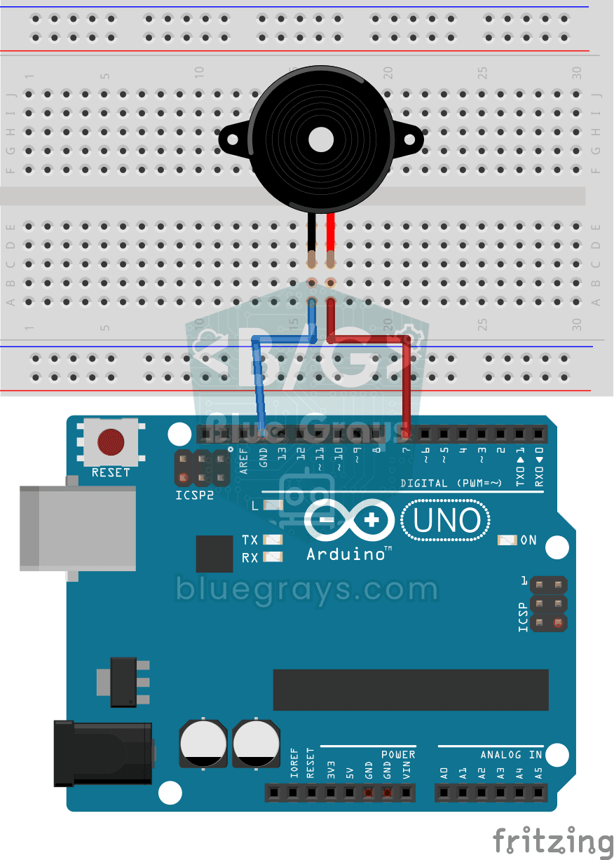
Ever wondered how a doorbell or an alarm makes its sound? The Arduino makes a small buzzer beep at short intervals: beep, pause, beep, pause.

LED Control with a Push Button (Push)
Just like a doorbell: the light stays on as long as you press, and goes off when you let go.

LED Blink
The very first hello of electronics: switching a single LED on and off. The Arduino turns the LED on and off at short intervals, so the light blinks quickly.

LED Blink with ESP32
Teaches basic GPIO output usage with ESP32. We achieve a blinking effect by turning an LED on and off from a digital pin. ESP32 version of the classic blink project on Arduino UNO; the basic blink commands in the Arduino environment are the same, but the ESP32's pin layout and 3.3 V GPIO levels differ from those of the Arduino UNO.
ESP32 Motion Alarm System (PIR + Buzzer + LED + Telegram)
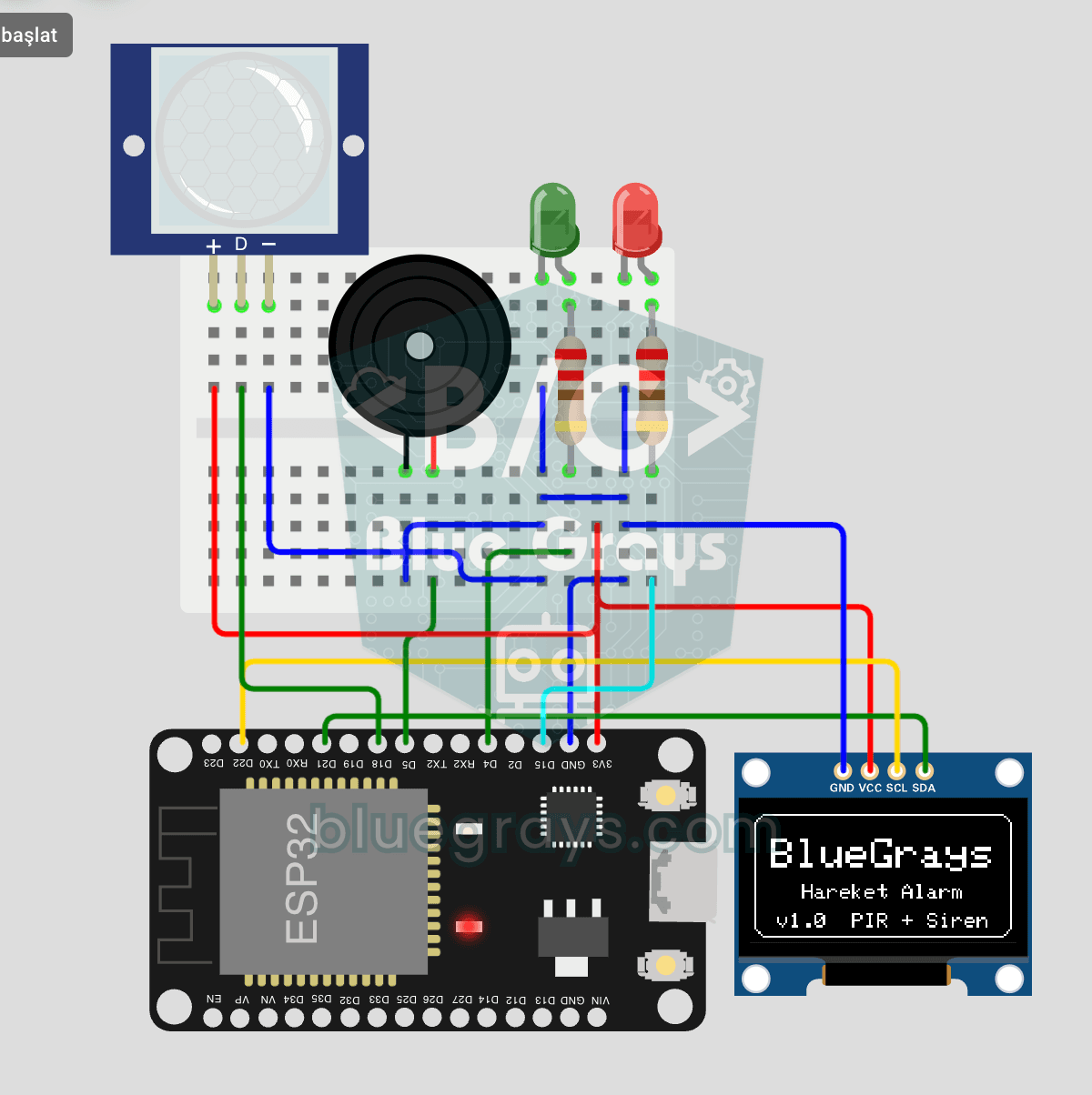
A smart security alarm: when the PIR sensor detects motion, it sounds the buzzer, lights the LED and sends the owner an instant Telegram notification. A 30-second cooldown limits how often the alarm repeats; it does not filter out the PIR sensor's false detections. Use it at home, in a garage, a storeroom or a study.
Raspberry Pi Pico Button Controlled LED (Push)
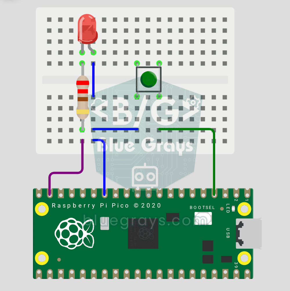
First input project with Pico — button read! LED lights while button is pressed, off when released. This is the big step after LED animations: signal input from the world to Pico. Learn Pin.IN (input mode), Pin.PULL_UP (internal pull-up resistor — standard for buttons), button.value() reading. GP14 LED, GP2 button (internal PULL_UP). Pressed = LOW (0), released = HIGH (1) — reverse logic seems confusing at first but is industry standard.