
Water Level Sensor Arduino: Calibration, Overflow Alarm and Pump
How to use a water level sensor with Arduino: empty/half/full calibration, pin powering against corrosion, buzzer overflow alarm, pump control, ESP32/Pico code.
A water level sensor is the cheapest and easiest way to detect how high the water is in a glass, an aquarium, a plant saucer or a small tank with an Arduino. As the exposed conductive traces on the board go under water, the voltage on its analog output rises; the Arduino reads that voltage with analogRead() and decides whether the water is “empty”, “half” or “full”. It connects with three wires, works with a few lines of code and is the starting point for many projects, from overflow alarms to automatic pump control.
In this guide you'll learn what's inside the module, why the reading never reaches 1023, how to do an empty/half/full calibration and how to prevent the corrosion that eats the sensor within a few weeks. Then you'll build a buzzer overflow alarm and a pump control that refills a tank on its own, compare the sensor briefly with a float switch and the contactless XKC-Y25, and finally see how to do the same job with the ESP32 and Raspberry Pi Pico.
What is a water level sensor and how does it work?
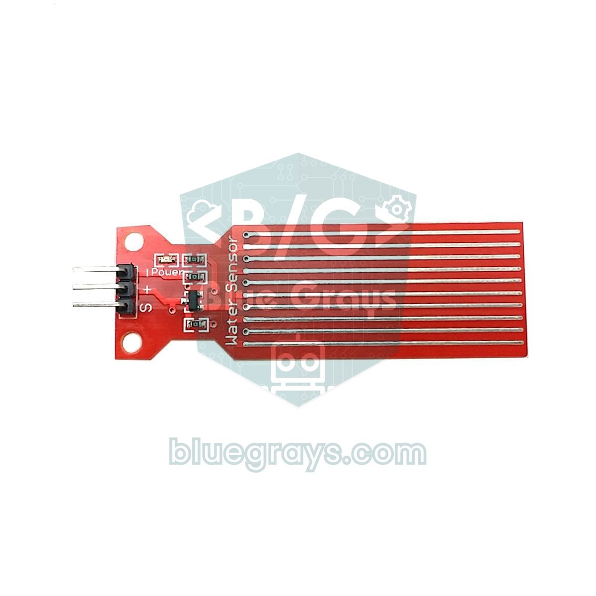
The lower part of the module carries ten conductive traces that don't touch each other and interlock like the teeth of two combs. Five of them are power traces tied to the + supply; the other five are sense traces that lead to the base of the S8050 NPN transistor on the top of the board. When the board is dry there's only air between the traces, the transistor is off and the S pin sits close to 0 V. Once the board is in water, the water bridges the power and sense traces; a small current flows into the transistor's base, the transistor starts to conduct and the voltage on the S output, taken from the emitter, rises. The higher the water, the longer the wetted length of trace, the lower the resistance between the traces and the higher the output voltage.
This way of working has three important consequences. First, the sensor doesn't really measure water but the water's conductivity: the dissolved minerals in tap water push the reading up, while pure (distilled) water gives almost nothing. Second, because the output comes from a transistor working as an emitter follower, the voltage never reaches the supply; a fully wet sensor powered at 5 V usually reads around 500–650 on an Arduino Uno and never gets anywhere near 1023. Third, the relationship isn't linear: the value climbs quickly over the first few millimetres and then slows down more and more. So this sensor isn't a ruler with millimetre accuracy but a practical indicator that reliably tells a few levels apart.
| Feature | Value |
|---|---|
| Operating voltage | 3.3–5 V DC |
| Operating current | Less than 20 mA (highest when fully wet) |
| Output | Analog voltage (S pin), rises as the water rises |
| Sensing area | About 40 × 16 mm, so at most about 4 cm of water height |
| Board size | About 62 × 20 mm |
| Operating temperature | 10–30 °C (manufacturer's figure) |
| Pins | S (signal), + (VCC), − (GND) |
Water level sensor wiring: Arduino Uno, ESP32 and Pico
| Sensor pin | Arduino Uno | ESP32 | Raspberry Pi Pico |
|---|---|---|---|
| S (signal) | A0 | GPIO 34 (ADC1) | GP26 (ADC0) |
| + (VCC) | D7 (powers it only while measuring) | GPIO 25 | GP15 |
| − (GND) | GND | GND | GND |
The easiest way to prevent corrosion is to power the sensor from a digital pin, as shown in the table: the code sets the pin HIGH just before a measurement, waits 10 ms, reads the value and sets the pin LOW again. In a system that measures once a second, the traces are energised only 1 percent of the time, which slows the wear by roughly a hundred times. When fully wet the module draws at most around 20 mA. The recommended limit for an Arduino Uno pin is 20 mA and the absolute maximum is 40 mA, and the pin is on for only a few milliseconds, so this connection is safe; ESP32 pins also supply this current easily. The Pico's pins, however, run with a lower default drive-strength setting, so when the sensor is fully wet the pin voltage sags a little and the readings get smaller. As long as you calibrate with the same wiring that's not a problem; if you want steadier values, you can switch the sensor's + with a small PNP transistor such as the BC557: the emitter goes to the board's 3V3 pin, the collector to the sensor's +, and the base to the GPIO pin through a 1 kΩ resistor, and the sensor then turns on when the pin is LOW. To pick a suitable transistor, have a look at the transistor tool.
Step by step: your first reading with Arduino
- Connect the sensor's S pin to A0, the + pin to D7 and the − pin to GND. Hold the board upright with the traces pointing down.
- Open the code below in the Arduino IDE, select Arduino Uno as the board, pick the right port and upload.
- Open the Serial Monitor and set it to 9600 baud. Check that the value is close to 0 while the sensor is dry.
- Lower the sensor slowly into a glass of water: first just the tip, then halfway, then up to the line where the traces end. At each step wait a few seconds and write down the value.
1const int SENSOR_PIN = A0;   // S → A0
2const int POWER_PIN = 7;     // + → D7 (yalnızca ölçerken besle / power only while measuring)
3
4int readSensor() {
5  digitalWrite(POWER_PIN, HIGH);        // sensörü aç / power the sensor
6  delay(10);                            // değerin oturmasını bekle / let the reading settle
7  long sum = 0;
8  for (int i = 0; i < 8; i++) {         // 8 ölçümün ortalaması / average of 8 readings
9    sum += analogRead(SENSOR_PIN);
10  }
11  digitalWrite(POWER_PIN, LOW);         // sensörü kapat / power off
12  return sum / 8;
13}
14
15void setup() {
16  pinMode(POWER_PIN, OUTPUT);
17  digitalWrite(POWER_PIN, LOW);         // kapalı başla / start powered off
18  Serial.begin(9600);
19}
20
21void loop() {
22  int raw = readSensor();
23  Serial.print("Ham deger / Raw value: ");
24  Serial.println(raw);
25  delay(1000);                          // saniyede bir ölç / measure once a second
26}
The readSensor() function keeps the sensor on for only about 11 ms per measurement. The 10 ms wait lets the transistor and the water between the traces settle to a stable value; then the average of 8 readings smooths out the small fluctuations of individual samples. On the Uno each analogRead() takes about 0.1 ms, so 8 readings take less than 1 ms. When you stir the water or shake the glass you'll see the values jump around in the Serial Monitor; that's normal, because the moving surface keeps changing the wetted length of the traces.
Empty, half, full: how to calibrate
Don't use the thresholds from code you find online as they are; every sensor, every kind of water and every supply voltage gives different values. Calibrate in the container where the sensor will really be used and with the same water: aquarium water for an aquarium, fertilised water for a fertilised irrigation tank. Draw lines at 0, 10, 20, 30 and 40 mm on the sensor with a marker, dip the board to each line, wait 3–4 seconds for the value to settle and write down the number in the Serial Monitor. The table below shows typical ranges for tap water and a 5 V supply; note your own values next to them.
| Level | Immersion depth | Typical Uno value (5 V, tap water) |
|---|---|---|
| Empty | 0 mm (dry) | 0–20 |
| Low | About 5–10 mm | 250–400 |
| Half | About 20 mm | 400–480 |
| Full | About 40 mm (line where the traces end) | 480–650 |
What stands out in the table is how fast the values rise in the first centimetre and then bunch up: there can be a difference of several hundred units between 0 and 10 mm but only a few dozen between 20 and 40 mm. That's why, instead of drawing a single straight line with map(), piecewise linear interpolation, which uses a separate ratio between each pair of measuring points, gives a much more accurate result. The code below keeps the five points you measured in two arrays, converts the raw value to millimetres and prints the level by name. All you need to do is write your own readings into the RAW array in ascending order.
1const int SENSOR_PIN = A0;
2const int POWER_PIN = 7;
3
4// Kendi kalibrasyon ölçümlerin / your own calibration readings
5const int N = 5;
6const int RAW[N] = {0, 330, 440, 490, 520};   // ham değer, küçükten büyüğe / raw value, ascending
7const int MM[N]  = {0, 10, 20, 30, 40};       // batma derinliği (mm) / immersion depth (mm)
8
9int readSensor() {
10  digitalWrite(POWER_PIN, HIGH);
11  delay(10);
12  long sum = 0;
13  for (int i = 0; i < 8; i++) sum += analogRead(SENSOR_PIN);
14  digitalWrite(POWER_PIN, LOW);
15  return sum / 8;
16}
17
18int rawToMm(int raw) {
19  if (raw <= RAW[0]) return MM[0];
20  for (int i = 1; i < N; i++) {
21    if (raw <= RAW[i]) {                      // iki nokta arasında oran kur / interpolate between two points
22      return map(raw, RAW[i - 1], RAW[i], MM[i - 1], MM[i]);
23    }
24  }
25  return MM[N - 1];                           // en üst noktanın üstü / above the top point
26}
27
28const char* levelName(int mm) {
29  if (mm < 3)  return "Bos / Empty";
30  if (mm < 15) return "Az / Low";
31  if (mm < 30) return "Yarim / Half";
32  return "Dolu / Full";
33}
34
35void setup() {
36  pinMode(POWER_PIN, OUTPUT);
37  digitalWrite(POWER_PIN, LOW);
38  Serial.begin(9600);
39}
40
41void loop() {
42  int raw = readSensor();
43  int mm = rawToMm(raw);
44  Serial.print(raw);
45  Serial.print(" -> ");
46  Serial.print(mm);
47  Serial.print(" mm, ");
48  Serial.println(levelName(mm));
49  delay(1000);
50}Overflow alarm with a buzzer
One of the most useful jobs for a water level sensor is warning you about an overflow: placed under the washing machine or the boiler, in a plant saucer, in an air conditioner's drain tray or on the rim of a bucket that's filling up, the sensor starts the alarm as soon as the water touches its tip. Even the “low” level from the calibration table is enough for this. The code below uses an active buzzer and the Uno's built-in LED; when the value passes ALARM_ON the buzzer beeps every quarter of a second, and when the value drops below ALARM_OFF it goes quiet. Because it uses millis() instead of delay() for the timing, the measurement and the buzzer don't block each other. For the types of buzzer see What Is a Buzzer?, and for the millis() idea see millis() and delay().
1const int SENSOR_PIN = A0;   // S → A0
2const int POWER_PIN = 7;     // + → D7
3const int BUZZER_PIN = 8;    // aktif buzzer + ucu / active buzzer +
4const int LED_PIN = 13;      // Uno'nun dahili LED'i / Uno's built-in LED
5
6const int ALARM_ON = 200;    // bu değer ve üstü taşma / at or above: overflow (kendin ölç / measure yours)
7const int ALARM_OFF = 100;   // bunun altına inince alarm biter / alarm clears below this
8
9bool alarmActive = false;
10bool buzzerOn = false;
11unsigned long lastRead = 0;
12unsigned long lastBeep = 0;
13
14int readSensor() {
15  digitalWrite(POWER_PIN, HIGH);
16  delay(10);
17  long sum = 0;
18  for (int i = 0; i < 8; i++) sum += analogRead(SENSOR_PIN);
19  digitalWrite(POWER_PIN, LOW);
20  return sum / 8;
21}
22
23void setup() {
24  pinMode(POWER_PIN, OUTPUT);
25  pinMode(BUZZER_PIN, OUTPUT);
26  pinMode(LED_PIN, OUTPUT);
27  digitalWrite(POWER_PIN, LOW);
28  Serial.begin(9600);
29}
30
31void loop() {
32  unsigned long now = millis();
33
34  if (now - lastRead >= 1000) {                       // saniyede bir ölç / measure once a second
35    lastRead = now;
36    int level = readSensor();
37    if (!alarmActive && level >= ALARM_ON) alarmActive = true;    // taşma başladı / overflow started
38    if (alarmActive && level < ALARM_OFF) alarmActive = false;    // su çekildi / water receded
39    Serial.print("Seviye / Level: ");
40    Serial.println(level);
41  }
42
43  if (alarmActive) {
44    if (now - lastBeep >= 250) {                      // 250 ms öt, 250 ms sus / 250 ms on, 250 ms off
45      lastBeep = now;
46      buzzerOn = !buzzerOn;
47      digitalWrite(BUZZER_PIN, buzzerOn ? HIGH : LOW);
48    }
49  } else if (buzzerOn) {
50    buzzerOn = false;
51    digitalWrite(BUZZER_PIN, LOW);
52  }
53  digitalWrite(LED_PIN, alarmActive ? HIGH : LOW);
54}
Pump control: refilling a tank on its own
The second classic application is automatic refilling that keeps the level within a band. You might want to top up the water that evaporates from an aquarium from a spare bucket, keep your pet's water bowl full or feed a greenhouse tank. The logic is simple: when the level drops below START_BELOW the pump runs, and when it reaches STOP_ABOVE it stops. The gap between these two thresholds is the hysteresis that keeps the pump from switching on and off constantly. Remember that the sensor only has a sensing area of about 4 cm; mount the board at a height where the band of water you want to hold falls inside those 4 cm.
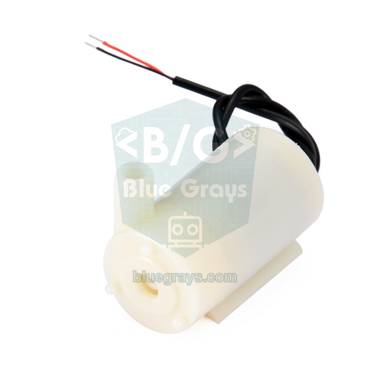
The pump draws far more current than an Arduino pin can supply, so drive it with a relay module or with a logic-level MOSFET and a flyback diode, power the pump from a separate supply and connect the GNDs of both supplies together. For details see What Is a Relay Module?, using a MOSFET and the mini water pump. The most important part of the code is a safety measure: if the pump runs for the whole MAX_RUN_MS period and the level still hasn't reached the target, the system locks the pump out and warns you with short beeps. The hose may have slipped out, the spare bucket may be empty or the sensor may have moved; without this lockout the pump could run dry for hours or flood the whole place.
1const int SENSOR_PIN = A0;
2const int POWER_PIN = 7;
3const int PUMP_PIN = 8;                 // röle IN / relay IN
4const int BUZZER_PIN = 9;               // aktif buzzer / active buzzer
5const bool RELAY_ACTIVE_LOW = true;     // çoğu röle modülü LOW ile çeker / most relay modules switch on LOW
6
7const int START_BELOW = 300;            // bunun altında doldur / start filling below this (kendin ölç / measure yours)
8const int STOP_ABOVE = 480;             // bu değerde dur / stop at this value
9const unsigned long MAX_RUN_MS = 30000; // en uzun çalışma 30 sn / max run time 30 s
10
11bool pumpOn = false;
12bool fault = false;
13unsigned long pumpStart = 0;
14
15int readSensor() {
16  digitalWrite(POWER_PIN, HIGH);
17  delay(10);
18  long sum = 0;
19  for (int i = 0; i < 8; i++) sum += analogRead(SENSOR_PIN);
20  digitalWrite(POWER_PIN, LOW);
21  return sum / 8;
22}
23
24void setPump(bool on) {
25  pumpOn = on;
26  bool pinHigh = RELAY_ACTIVE_LOW ? !on : on;
27  digitalWrite(PUMP_PIN, pinHigh ? HIGH : LOW);
28}
29
30void setup() {
31  setPump(false);              // pin çıkış olmadan önce kapalı konuma al / set off before the pin becomes an output
32  pinMode(PUMP_PIN, OUTPUT);
33  pinMode(POWER_PIN, OUTPUT);
34  pinMode(BUZZER_PIN, OUTPUT);
35  digitalWrite(POWER_PIN, LOW);
36  Serial.begin(9600);
37}
38
39void loop() {
40  if (fault) {                 // arıza: pompa kilitli, kesik kesik öt / fault: pump locked out, beep
41    digitalWrite(BUZZER_PIN, HIGH);
42    delay(200);
43    digitalWrite(BUZZER_PIN, LOW);
44    delay(1800);
45    return;                    // yeniden başlatmak için reset / press reset to restart
46  }
47
48  int level = readSensor();
49
50  if (!pumpOn && level < START_BELOW) {
51    setPump(true);             // seviye düştü, doldur / level low, start filling
52    pumpStart = millis();
53  } else if (pumpOn && level >= STOP_ABOVE) {
54    setPump(false);            // istenen seviyeye ulaşıldı / target level reached
55  } else if (pumpOn && millis() - pumpStart > MAX_RUN_MS) {
56    setPump(false);            // süre doldu, seviye yükselmedi / timed out, level did not rise
57    fault = true;
58  }
59
60  Serial.print("Seviye / Level: ");
61  Serial.print(level);
62  Serial.println(pumpOn ? "  pompa / pump ON" : "  pompa / pump OFF");
63  delay(500);
64}
Water level sensor vs float switch vs XKC-Y25
| Feature | Water level sensor (conductive traces) | Float switch | XKC-Y25 (contactless) |
|---|---|---|---|
| Sensing method | Conductivity of the water | Floating magnet and reed contact | Change in capacitance behind the container wall |
| Output | Analog (a few levels) | Open or closed contact | Digital (liquid present or not) |
| Measuring range | About 0–4 cm | One point (mounting height) | One point (mounting height) |
| Contact with water | Yes, traces in the water | Yes, body in the water | No, sticks to the outside of the container |
| Corrosion | Yes; powering from a pin is a must | Practically none | None |
| Supply | 3.3–5 V | Not needed (passive contact) | 5–24 V, about 5 mA |
| Best for | Experiments, overflow alarms, small containers | Permanent tanks, pump protection | Closed plastic or glass tanks, corrosive liquids |
| Price | Cheapest | Cheap | More expensive than the others |
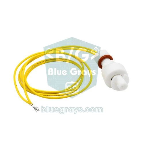
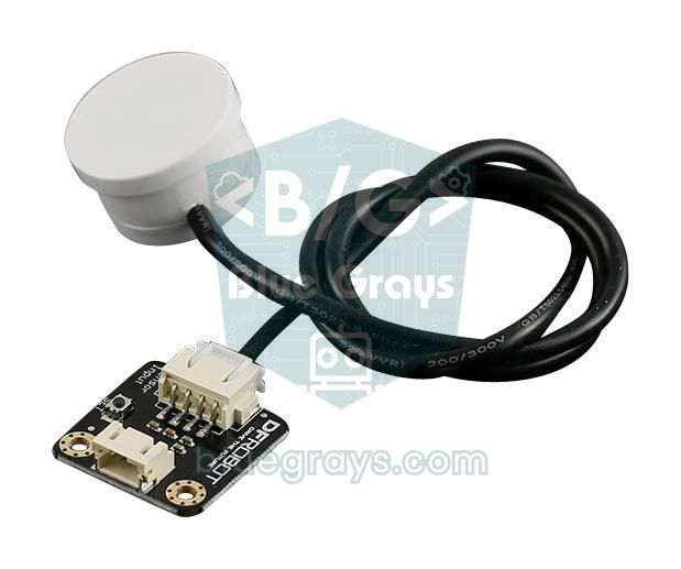
A float switch consists of a stem with a reed contact inside and a float with a magnet that slides along it. As the water rises the float lifts, the magnet lines up with the reed contact and the contact closes or opens. By fitting the float upside down on the stem you can swap between normally open (NO) and normally closed (NC) behaviour. To connect it to an Arduino, wire one lead to a digital pin and the other to GND and set the pin to INPUT_PULLUP; since there's no electrolysis wear, it lasts much longer in permanent installations. The contacts of small models are usually limited to around 0.5 A and 10 W, so drive the pump through a relay, not directly. For how a reed contact works, see the Reed Switch article.
1const int FLOAT_PIN = 2;    // bir kablo D2'ye, diğeri GND'ye / one wire to D2, the other to GND
2
3void setup() {
4  pinMode(FLOAT_PIN, INPUT_PULLUP);   // dahili pull-up direnci / internal pull-up resistor
5  Serial.begin(9600);
6}
7
8void loop() {
9  // Kontak kapalıyken pin LOW okunur / the pin reads LOW when the contact is closed
10  if (digitalRead(FLOAT_PIN) == LOW) {
11    Serial.println("Kontak kapali / Contact closed");
12  } else {
13    Serial.println("Kontak acik / Contact open");
14  }
15  delay(500);
16}
The XKC-Y25, on the other hand, is a capacitive sensor that never touches the water: you stick it to the outside of a plastic or glass tank and it detects whether there's liquid behind the wall. According to the manufacturer it runs on 5–24 V, draws about 5 mA, can sense through non-metallic walls up to 13 mm thick and responds in about 500 ms. The high level of its output equals the supply voltage, so when you connect an XKC-Y25 powered at 5 V to an ESP32 or Pico you should use a voltage divider (the voltage divider tool works out the right resistors). We cover the sensitivity adjustment and the models with different outputs in detail in the XKC-Y25 contactless level sensor article.
Monitoring the water level from your phone with the ESP32
With the ESP32 you can bring the measurement to your phone over Wi-Fi. Always connect the sensor's S pin to an ADC1 pin (GPIO 32–39); ADC2 pins can't be read while Wi-Fi is on. The ESP32's ADC is 12-bit, so values range from 0 to 4095, and because the sensor is powered at 3.3 V the numbers can't be compared with the Uno's; you'll need to calibrate again. The ESP32's ADC isn't fully linear near 0 V and near the top of its range, but since what matters here is the difference between levels rather than the absolute voltage, that's not a problem. The code below takes a reading every two seconds and serves a small web page that refreshes itself every five seconds, which you can open from your phone on the same network.
1#include <WiFi.h>
2#include <WebServer.h>
3
4const char* WIFI_SSID = "WIFI_ADIN";      // ağ adın / your network name
5const char* WIFI_PASS = "WIFI_SIFREN";    // ağ şifren / your network password
6
7const int SENSOR_PIN = 34;   // S → GPIO 34 (ADC1, Wi-Fi ile çalışır / works with Wi-Fi)
8const int POWER_PIN = 25;    // + → GPIO 25
9const int HALF = 1500;       // yarım eşiği / half threshold (kendin ölç / measure yours)
10const int FULL = 2000;       // dolu eşiği / full threshold (kendin ölç / measure yours)
11
12WebServer server(80);
13int lastRaw = 0;
14unsigned long lastRead = 0;
15
16int readSensor() {
17  digitalWrite(POWER_PIN, HIGH);
18  delay(10);
19  long sum = 0;
20  for (int i = 0; i < 16; i++) sum += analogRead(SENSOR_PIN);   // 0–4095
21  digitalWrite(POWER_PIN, LOW);
22  return sum / 16;
23}
24
25const char* levelName(int raw) {
26  if (raw < 100) return "Bos / Empty";
27  if (raw < HALF) return "Az / Low";
28  if (raw < FULL) return "Yarim / Half";
29  return "Dolu / Full";
30}
31
32void handleRoot() {
33  String html = "<!DOCTYPE html><html><head><meta charset='utf-8'>"
34                "<meta name='viewport' content='width=device-width'>"
35                "<meta http-equiv='refresh' content='5'></head><body>"
36                "<h1>Su seviyesi / Water level</h1><h2>";
37  html += levelName(lastRaw);
38  html += "</h2><p>Ham deger / Raw: ";
39  html += lastRaw;
40  html += "</p></body></html>";
41  server.send(200, "text/html", html);
42}
43
44void setup() {
45  Serial.begin(115200);
46  pinMode(POWER_PIN, OUTPUT);
47  digitalWrite(POWER_PIN, LOW);
48  WiFi.begin(WIFI_SSID, WIFI_PASS);
49  while (WiFi.status() != WL_CONNECTED) {   // bağlanana kadar bekle / wait until connected
50    delay(500);
51    Serial.print(".");
52  }
53  Serial.println();
54  Serial.print("Adres / Address: http://");
55  Serial.println(WiFi.localIP());
56  server.on("/", handleRoot);
57  server.begin();
58}
59
60void loop() {
61  server.handleClient();
62  if (millis() - lastRead >= 2000) {        // 2 sn'de bir ölç / measure every 2 s
63    lastRead = millis();
64    lastRaw = readSensor();
65  }
66}
Before uploading, replace WIFI_SSID and WIFI_PASS with your own network details; the ESP32 only connects to 2.4 GHz networks. When you open the Serial Monitor at 115200 baud, just type the address it shows into your phone's browser. If you'd like a notification on your phone when the level is “full”, you can turn the same reading into a message with the method from the ESP32 Telegram bot article.
Overflow alarm with Raspberry Pi Pico and MicroPython
On the Raspberry Pi Pico the GP26, GP27 and GP28 pins are used for analog readings. MicroPython's read_u16() function scales the Pico's 12-bit measurement to the 0–65535 range, so your thresholds will be much bigger numbers than on the Uno. The code below powers the sensor from GP15, reads the S output on GP26 and gives an overflow warning with three short beeps from an active buzzer on GP14. As with the first sketch, set the thresholds from your own measurements.
1from machine import ADC, Pin
2import time
3
4sensor = ADC(26)                    # GP26 (ADC0) → S
5power = Pin(15, Pin.OUT, value=0)   # GP15 → sensör + / sensor +
6buzzer = Pin(14, Pin.OUT, value=0)  # GP14 → aktif buzzer / active buzzer
7
8ALARM_ON = 20000    # bu değer ve üstü taşma / at or above: overflow (kendin ölç / measure yours)
9ALARM_OFF = 10000   # bunun altında alarm biter / alarm clears below this
10
11def read_level(samples=8):
12    power.value(1)
13    time.sleep_ms(10)               # değerin oturmasını bekle / let the reading settle
14    total = 0
15    for _ in range(samples):
16        total += sensor.read_u16()  # 0–65535
17    power.value(0)
18    return total // samples
19
20alarm = False
21while True:
22    level = read_level()
23    if not alarm and level >= ALARM_ON:
24        alarm = True
25    elif alarm and level < ALARM_OFF:
26        alarm = False
27    print("Seviye / Level:", level, "ALARM" if alarm else "")
28    if alarm:
29        for _ in range(3):          # üç kısa bip / three short beeps
30            buzzer.value(1)
31            time.sleep_ms(150)
32            buzzer.value(0)
33            time.sleep_ms(150)
34    else:
35        time.sleep(1)
Project ideas with a water level sensor
- Plant saucer overflow warning: A buzzer that sounds when water collects in the saucer after watering; combine it with a soil moisture sensor and you have a complete watering system.
- Automatic aquarium top-off: A time-limited refill system that replaces evaporated water from a spare bucket with a mini pump.
- Pet water bowl: A reminder that lights an LED or sends a notification to your phone via the ESP32 when the bowl runs low.
- Water leak detector: A leak alarm with the sensor laid flat on the floor under a washing machine or boiler, or in a basement.
- Smart greenhouse tank: Protection that watches the level of the irrigation tank and locks the pump out when it runs dry; it slots easily into the smart greenhouse project.
- Rain barrel gauge: A panel that shows the level as empty, half or full on an I2C LCD display; you can also add a rain sensor to catch the moment the rain starts.
Common mistakes and how to fix them
| Symptom | Likely cause | Fix |
|---|---|---|
| The value is always 0, even in water | The + pin isn't powered (POWER_PIN never goes HIGH) or S is on the wrong pin | Check the pinMode and digitalWrite lines and that S is wired to an analog pin |
| The value jumps around randomly even when dry | The S pin is floating or GND isn't connected | Check all three wires; the GND must be common |
| It never reaches 1023, even fully submerged | That's normal; the output comes from an emitter follower | Set your thresholds from the highest value you measured yourself |
| No reading at all in pure water | Distilled or purified water has very low conductivity | Use an XKC-Y25 or a float switch with this kind of water |
| The values drop or drift over a few weeks | Electrolysis and deposits on the traces | Power the sensor from a pin, clean the traces with a soft brush and replace the sensor if needed |
| The pump or buzzer keeps toggling at the threshold | A single threshold is used; the moving surface makes the value wobble | Use two separate thresholds for on and off (hysteresis) and average the readings |
| On the ESP32 the value can't be read once Wi-Fi connects | The sensor is on an ADC2 pin | Move S to an ADC1 pin between GPIO 32 and 39 |
The water level sensor teaches analog readings, calibration, hysteresis and real-world problems such as corrosion with a single cheap module. If you need to measure the level of a large tank centimetre by centimetre, you can move to an ultrasonic solution such as the HC-SR04 distance sensor. In the BlueGrays app you'll find the smart irrigation station and buzzer alarm projects with step-by-step circuit diagrams and code, and you can easily add the water level sensor to them.
Frequently asked questions
How does a water level sensor work?
As the interleaved conductive traces on the board go into the water, the water bridges them and current flows into the base of the S8050 transistor on the board. The more the transistor conducts, the higher the voltage on the S pin; the Arduino reads that voltage with analogRead() to tell how high the water is.
Why does my water level sensor corrode?
When direct current keeps flowing through the wet traces, electrolysis starts and the plating on the traces tied to + dissolves. If you power the sensor from a digital pin instead of 5V and switch it on for only a few milliseconds per reading, the wear slows down dramatically and the sensor lasts for months.
Does a water level sensor work in distilled water?
Not really. Because the sensor measures the water's conductivity, distilled or purified water without dissolved minerals gives very low readings. For this kind of water, sensors that don't depend on conductivity, such as the contactless XKC-Y25 or a float switch, are the better choice.
Why doesn't the water level sensor reading reach 1023?
The S output is taken from the transistor's emitter, so the voltage stays below the supply, and the base current is limited by the resistance of the water. On an Arduino Uno at 5 V a fully wet sensor usually reads around 500–650, so set your thresholds based on that maximum.
Can a water level sensor be fully submerged?
No. Only the lower part with the conductive traces should go into the water; if the upper part with the transistor, LED and pins gets wet, it shorts out and the sensor reads wrongly or fails. Protecting the electronics with hot glue or lacquer makes it last longer.
How do you measure the level of a large water tank?
This sensor only covers a range of about 4 cm, so it isn't suitable for large tanks. To measure the level continuously, waterproof ultrasonic sensors such as the JSN-SR04T mounted in the tank lid are used; to watch just a few critical points, float switches are placed at different heights.
Projects to build after reading this
See all projects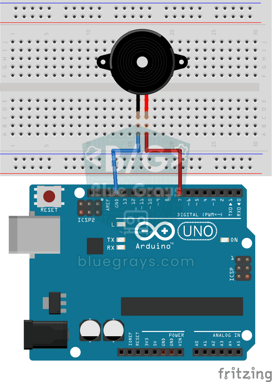
Using a Buzzer
Ever wondered how a doorbell or an alarm makes its sound? The Arduino makes a small buzzer beep at short intervals: beep, pause, beep, pause. You see how sound is made with electricity and take the fi

Measuring Light Intensity with an LDR
Want to see how bright your room is as a number? The LDR, a small part that reacts to light, measures the light around it, and the Arduino writes the value to your computer screen every half second. C

Reading Light Intensity with the ESP32 LDR Module
Real-time monitoring of the LDR module's raw ADC value and relative light percentage calculated from dark and light reference values in the Serial Monitor. This percentage is not a lux measurement. Teaches the module’s calibration logic. It is ideal to complete this before Project 10, as it is used to determine the threshold value.

Smart Irrigation Station
A gardener that waters your plants on its own, so they don't dry out while you're on vacation. A soil moisture sensor measures how wet the soil is; when it gets dry, the Arduino runs the water pump fo
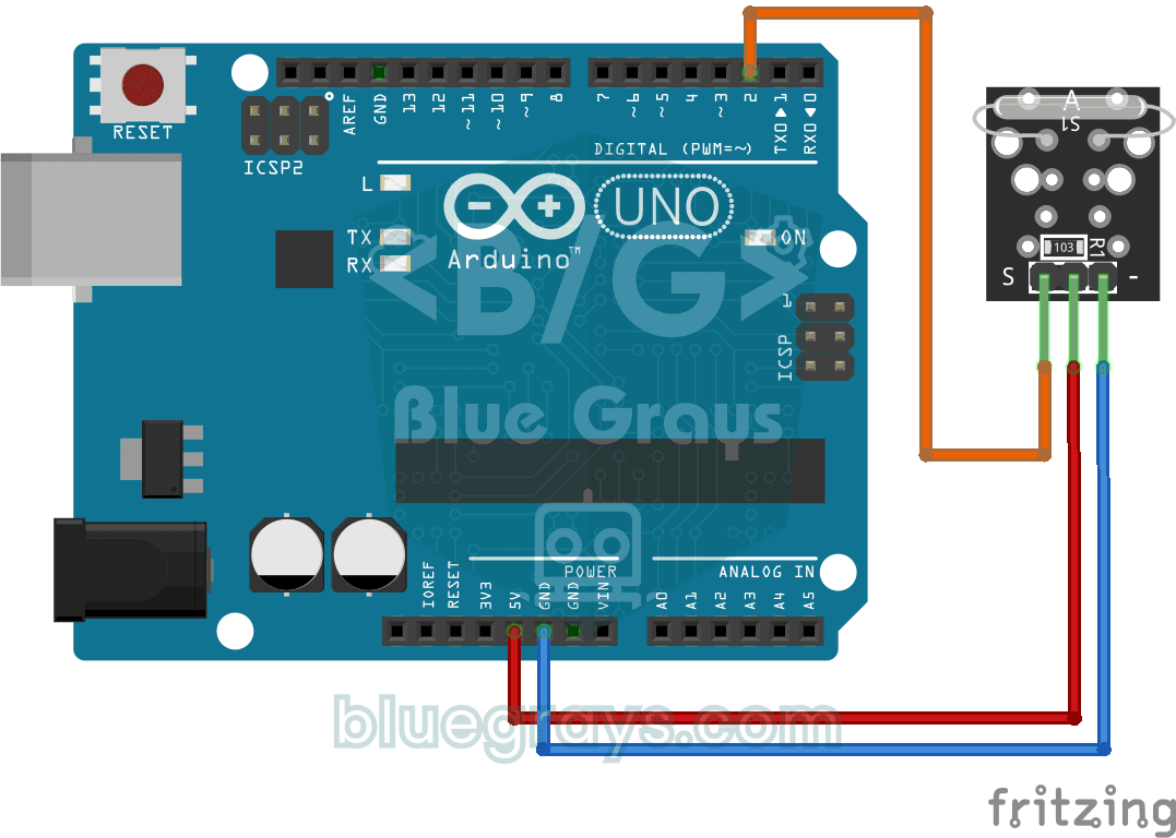
Reading a Reed Switch
Ever wondered about the magnetic switch inside door and window alarms? When a magnet comes near the reed relay module, the tiny switch inside it closes; the Arduino reads it once a second and prints 0

ESP32 Asynchronous Web Server (with IP Display on LCD)
In this project, we’re turning the ESP32 into an asynchronous web server that you can control from your phone or computer on the same Wi-Fi network. Thanks to the ESPAsyncWebServer library, the server can process multiple requests simultaneously (unlike the classic WebServer.h, which blocks on a single request). You’ll be able to open the ESP32’s IP address in a browser and click the ON/OFF buttons (the /on and /off routes) to turn the LED connected to GPIO 5 on and off.
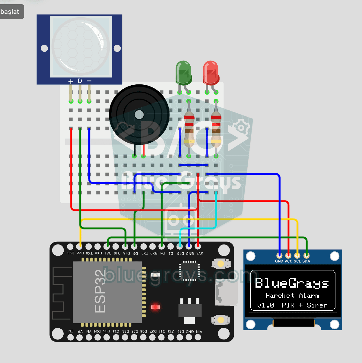
ESP32 Motion Alarm System (PIR + Buzzer + LED + Telegram)
A smart security alarm system that activates the buzzer and LED when the PIR sensor detects motion, while simultaneously sending an instant notification to the owner via Telegram. It includes a 30-second cooldown to limit the frequency of repeated alarms; this mechanism does not validate PIR detections or eliminate false triggers. Suitable for home security, garage monitoring, warehouses, or workrooms. With ESP32-CAM, photo notifications can be added; with the classic ESP32 DevKit V1, text notif