
Ohm's Law Activity for Students: 2-Lesson Plan with LEDs
Ohm's law activity for students: two 40-minute lessons where they predict, calculate and measure LED current. Materials list, Arduino code and worksheet.
A good Ohm's law activity for students does not start by writing the formula on the board and asking them to memorise it. It starts with a prediction that students then test in their own circuit. The lesson plan below runs over two lessons (2 × 40 minutes) and has four steps: predict (which resistor makes the LED brighter?), calculate (how many milliamps flow, using V = I × R?), observe and measure (how bright is the LED, what voltage does the Arduino read?) and compare (why are the prediction, the calculation and the measurement close but not identical?). Once students have used the formula with their own hands, they remember what V, I and R mean from experience rather than from a list.
We are not repeating the theory here: the formula itself, the units and the power calculation are in what is Ohm's law, and how a resistor and an LED work is covered in what is a resistor and what is an LED. This post focuses on what you take into the classroom: learning objectives, a materials table for a class of 24, a minute-by-minute plan for both lessons, a short Arduino measuring sketch that compiles, a measurement table template, a 6-question worksheet with answer key, common misconceptions, and ideas for differentiating between fast and slow groups.
How the activity works: predict, calculate, measure, compare
| Stage | What students do | Output | Lesson |
|---|---|---|---|
| 1. Predict | Write down, with a reason, which resistor will make the same LED shine brighter | Prediction card (one sentence + ranking) | Lesson 1, first 5 minutes |
| 2. Calculate | Read the resistor value from the color code, look up the LED forward voltage, calculate the current with V = I × R | Prediction table (current for 4 resistors) | Lesson 1 |
| 3. Observe and measure | Build the circuit, rate the brightness 1–5, read the LED and resistor voltages with the Arduino | Measurement table | Lesson 2 |
| 4. Compare | Put calculated and measured current side by side and explain the difference | Worksheet + exit question | Lesson 2, last 10 minutes |
The point of this order is to turn the formula from an answer machine into a checking tool. If a student makes a wrong prediction in the first minute (many will say “the bigger resistor is stronger, so it makes the LED brighter”), that is not a problem, it is the material of the lesson. Seeing their own prediction fail with their own eyes in the second lesson sticks far better than reading the same fact from the board. Working with a single LED color (red) throughout is a deliberate choice too: when the resistor is the only variable, students can clearly see what changes what. The other colors are kept as extension tasks for fast groups.
Learning objectives and prior knowledge
- Reads the value of a four-band resistor from its color code and checks it with an app.
- Calculates the third quantity in V = I × R when two are known, and converts milliamps and kilohms correctly.
- Explains that an LED needs a certain forward voltage to light up, and that the voltage across the resistor is the supply voltage minus that value.
- Shows by experiment that a larger resistor means less current and a dimmer LED, and gives at least two reasons for the gap between calculated and measured values.
- Concludes from the measurement table that an LED does not behave like a resistor: its voltage changes very little while the current changes several times over.
As prior knowledge, it is enough for students to have heard the words voltage, current and resistance. The plan also works with a class that has never seen the formula; you just stretch the triangle section in the first lesson by a few minutes. Knowing how to connect two parts in series on a breadboard makes things much easier. If they do not, show the internal connection diagram from what is a breadboard as a five-minute warm-up in the lesson before. No Arduino experience is needed: you can upload the sketch for the second lesson in advance, and students only open the Serial Monitor and read the numbers. The plan was written with roughly 12 to 15 year olds in mind, but the same flow works in vocational courses and introductory electronics workshops.
Materials list: per group and for a class of 24
| Item | Per group (3 students) | Class of 24 (8 groups) | Note |
|---|---|---|---|
| Arduino Uno + USB cable | 1 | 8 | Used as the 5 V supply and as a voltmeter; the cable must be a data cable |
| Breadboard (half size is enough) | 1 | 8 | Without an Arduino, a breadboard power module with a 5 V output also works |
| Red LED (5 mm) | 2 | 16 + 4 spares | Main color of the experiment |
| Green LED | 1 | 8 | For fast groups |
| Blue LED | 1 | 8 | For fast groups; higher forward voltage |
| 220 Ω resistor | 2 | 16 | The second one is for the series task |
| 330 Ω resistor | 1 | 8 + 4 spares | Given pre-mounted in the ready-made circuit for slower groups |
| 1 kΩ resistor | 2 | 16 | The second one is for the parallel task |
| 100 Ω resistor | - | 1 (teacher's desk) | Used only in calculations and discussion, never plugged in |
| Male-to-male jumper wires | 5 | 40 + 10 spares | Colored wires make 5 V and GND easier to tell apart |
| Multimeter | 1 (if available) | 2–8 | Without one, the Arduino's A0 input does the measuring |
| Phone with BlueGrays installed | at least 1 | 8 | The Color code, Ohm's law, LED resistor and LED voltages tools are free |
| Worksheet + prediction card | 3 | 24 | One printout per student |
Option without a multimeter: the Arduino Uno's analog input turns 0 to 5 V into a number between 0 and 1023, so the board is a 5 V supply and a simple voltmeter at the same time. The second lesson of this plan is built exactly that way; a multimeter is only a bonus for groups who want to answer “how many volts does the 5 V pin really give?” or measure current directly. If you have a few multimeters, you can do the current measurement as a demonstration at your desk; the right range and where to plug the probes are explained in how to use a multimeter. If you have neither Arduinos nor multimeters, the first lesson runs unchanged, and in the second lesson you only do the brightness experiment and leave the measurement columns empty.
Lesson 1 (40 minutes): prediction and calculation
| Minutes | Section | What the teacher does | What students do | Tool |
|---|---|---|---|---|
| 0–5 | Warm-up question | Asks “If we put 220 Ω on the same red LED once and 1 kΩ once, which one is brighter, and why?” and takes a show of hands | Write their prediction and a one-sentence reason on the prediction card | - |
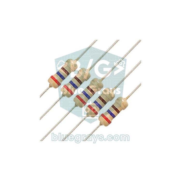
| 5–12 | Resistor color code | Shows the band order and which side the tolerance band sits on | Read the 4 resistors in their bag from the colors, check them in the app | Color code |
| 12–20 | The V = I × R triangle | Draws the triangle: V on top, I and R below; shows how to cover the unknown with a finger | Solve 3 short examples on paper first, then check in the app | Ohm's law |
| 20–26 | LED forward voltage | Explains that an LED needs a threshold voltage to light and that the long leg is the anode | Look up the typical value for red, green and blue LEDs and write it in the table | LED voltages |
| 26–35 | LED resistor calculation | Writes I = (5 V − LED voltage) / R on the board, solves one row together | Calculate the current for 4 resistors, fill in the prediction table, check with the app | LED resistor |
| 35–40 | Sharing and exit | Has two groups write their tables on the board, does not return to the warm-up question (answer comes in lesson 2) | Answer the exit questions | - |
Do not give away the answer to the warm-up question; collect the prediction cards and keep them for the second lesson. Some students will say “1 kΩ is bigger, so it gives more energy”, others will predict correctly and write “a resistor holds back current” as the reason. When both groups' reasons are read out again at the end of lesson 2, the discussion starts on its own. In the color code section, students read the bands and then check the result on the phone with the Color code tool; the tool is not there to do the reading but to confirm the student's own reading. So set the rule from the start: write it on paper first, then check.
In the triangle section, do not make them memorise the formula in three separate forms; one triangle is enough. When you cover the unknown with a finger, the two remaining letters are either side by side (multiply) or one above the other (divide). Three examples we suggest: 5 V and 1 kΩ, how many mA (5 mA)? 2 V and 10 mA, how many ohms (200 Ω)? 20 mA and 150 Ω, how many volts (3 V)? Students check the result by entering two values in the Ohm's law tool. Units are the most common mistake: a student who writes 10 instead of 10 mA gets an absurd result like 0.2 Ω. To catch this, ask “does the result make sense?” out loud for every example.
The LED section is the key part of the activity. Tell students that an LED does not glow a little at any voltage like a bulb: a red LED passes almost no current below 1.6–1.7 V, and around 2 V the current rises very quickly. So about 2 V of the 5 V supply stays across the LED, the remaining 3 V drops across the resistor, and it is this 3 V that sets the current. Have them look up typical values per color in the LED voltages tool; it shows about 1.85 V for red, and in class we round it to 2 V to keep the arithmetic easy. That small gap makes a good question too: with 220 Ω, is the current 13.6 mA or 14.3 mA? Both mean “about 14 mA”. Then each group calculates the current for its four resistors, enters that current in the LED resistor tool and sees that the resistor it suggests is close to their own. The table below is the teacher's answer key; values are calculated with a 5 V supply.
| LED | Forward voltage (approx.) | 100 Ω | 220 Ω | 330 Ω | 1 kΩ |
|---|---|---|---|---|---|
| Red (rounded for class) | 2.0 V | 30 mA | 13.6 mA | 9.1 mA | 3.0 mA |
| Red (typical value in the tool) | 1.85 V | 31.5 mA | 14.3 mA | 9.5 mA | 3.2 mA |
| Green (older, yellowish type) | 2.2 V | 28 mA | 12.7 mA | 8.5 mA | 2.8 mA |
| Blue | 3.3 V | 17 mA | 7.7 mA | 5.2 mA | 1.7 mA |
- Exit question 1: Which passes more current, 220 Ω or 330 Ω? Justify it with a number.
- Exit question 2: In a 5 V circuit, if there are 2 V across the red LED, how many volts are across the resistor?
- Exit question 3: A blue LED has a higher forward voltage than a red one. With the same 220 Ω, does the blue LED's current go up or down?
Lesson 2 (40 minutes): brightness experiment and Arduino measurement
| Minutes | Section | What the teacher does | What students do |
|---|---|---|---|
| 0–4 | Recap and safety | Hands back the prediction tables; sets the rule that USB is unplugged while changing wires or resistors | Put their own prediction table on the desk |
| 4–14 | Brightness experiment | Gives the order: 1 kΩ first, then 330 Ω, 220 Ω last | Light the red LED with each resistor and rate the brightness 1–5 |
| 14–18 | A0 connection | Has them open the Serial Monitor (9600 baud) on Arduinos with the sketch already uploaded | Plug the A0 wire into the point where the resistor meets the LED |
| 18–30 | Measurement | Walks between groups, catching reversed LEDs and loose A0 wires | Write the LED and resistor voltage for each resistor in the table, calculate the current with I = V / R |
| 30–36 | Comparison | Reads the warm-up prediction cards out again | Write down reasons for the gap between calculated and measured current |
| 36–40 | Worksheet | Gives the first 3 questions in class and the rest as homework | Start the worksheet |
Starting the brightness experiment at 1 kΩ matters: going from the dimmest circuit to the brightest, students see the difference more clearly and their eyes do not tire. Give a shared brightness scale: 1 “barely visible”, 3 “easy to see in room light”, 5 “uncomfortable to look at”. Comparing different colors by eye is misleading, because the eye is more sensitive to green than to red or blue; at the same current a green LED can look brighter. So always compare brightness within one color. These two lessons also fit as an extra day in the 5-day Arduino workshop program; they sit well right after the workshop's first LED day.
Build the circuit and turn the Arduino into a voltmeter
- With the USB cable unplugged, connect the Arduino's 5V pin to a row on the breadboard.
- Plug one leg of the resistor into the same row and the other leg into an empty row.
- Plug the red LED's long leg (anode) into the same row as the resistor's second leg, and its short leg (cathode) into another row.
- Connect the LED's cathode row to the Arduino's GND pin.
- Run a wire from the row where the resistor meets the LED's anode to the Arduino's A0 pin.
- Plug in USB, open the Serial Monitor at 9600 baud and write the two values that arrive every second into the measurement table.
- Unplug USB, swap the resistor for the next one and repeat step 6. You do not need to upload the sketch again.
1// Ohm kanunu etkinliği: LED ve direnç gerilimini ölç / Ohm's law activity: measure LED and resistor voltage
2// Devre / Circuit: 5V -> direnç / resistor -> A0 + LED anot / anode -> LED katot / cathode -> GND
3const float VCC = 5.00;      // 5V pinindeki gerilim, multimetre varsa ölçüp yaz / voltage on the 5V pin, measure it if you have a multimeter
4const int SENSE_PIN = A0;    // direnç ile LED'in birleştiği nokta / node where the resistor meets the LED
5const int SAMPLES = 20;      // ortalaması alınacak okuma sayısı / number of readings to average
6
7void setup() {
8  Serial.begin(9600);
9  Serial.println(F("V_LED (V)   V_R (V)"));
10}
11
12void loop() {
13  long sum = 0;
14  for (int i = 0; i < SAMPLES; i++) {
15    sum += analogRead(SENSE_PIN);         // 0-1023
16    delay(5);
17  }
18  float raw = sum / (float)SAMPLES;       // ortalama okuma / average reading
19  float vLed = raw * VCC / 1023.0;        // LED üzerindeki gerilim / voltage across the LED
20  float vRes = VCC - vLed;                // direnç üzerindeki gerilim / voltage across the resistor
21
22  Serial.print(vLed, 2);
23  Serial.print(F("        "));
24  Serial.println(vRes, 2);                // akımı kağıtta bul: I = V_R / R / find the current on paper: I = V_R / R
25  delay(1000);
26}
The sketch deliberately does not calculate the current: the Serial Monitor only prints the voltage across the LED and across the resistor, and students work out the current on paper with I = V_R / R. That way Ohm's law is used once more at the end of the lesson, this time with a real measurement, and the sketch never needs re-uploading when the resistor changes. analogRead() turns the voltage at A0 into a number from 0 to 1023; with a 5 V reference one step is about 4.9 mV. For a class that has not seen how this number is read, the analog reading example in what is a potentiometer is good preparation. Because the sketch averages 20 readings, the numbers do not jump around on screen. The 5 V coming from USB is usually between 4.7 and 5.1 V; if you have a multimeter, measure between 5V and GND once and enter it in the VCC line, which makes both columns a few percent more accurate.
| Resistor | Calculated current (lesson 1) | Brightness (1–5) | Measured LED voltage (V) | Measured resistor voltage (V) | Current from measurement = V_R / R (mA) | Difference and likely reason |
|---|---|---|---|---|---|---|
| 1 kΩ | 3.0 mA | .... | .... | .... | .... | .................... |
| 330 Ω | 9.1 mA | .... | .... | .... | .... | .................... |
| 220 Ω | 13.6 mA | .... | .... | .... | .... | .................... |
| 100 Ω (not built) | 30 mA | - | - | - | - | Why didn't we build it? |
The table students end up with looks roughly like this: as the resistor drops from 1 kΩ to 220 Ω, the current rises four to five times and the brightness score climbs from 1–2 to 4–5, yet the LED voltage rises by only a few tenths of a volt, typically staying between 1.8 and 2.0 V for a red LED. This is the most valuable moment of the lesson, because students see from their own numbers that an LED does not behave like a resistor: we apply Ohm's law to the resistor and treat the LED as a part that drops a roughly fixed voltage. A gap of a few percent between calculation and measurement is normal; let students find the reasons themselves. Expected answers: the USB voltage is not exactly 5 V, the resistors have ±5% tolerance, the LED's real forward voltage differs from our rounded 2.0 V, and one step of the analog reading is about 5 mV.
Worksheet: 6 questions and answer key
| No. | Question | Answer key |
|---|---|---|
| 1 | What are the value and tolerance of a resistor with brown, black, red and gold bands? | 1 and 0, then ×100: 1000 Ω = 1 kΩ, gold band ±5% |
| 2 | A 5 V supply, a red LED with a 2 V forward voltage and a 220 Ω resistor are in series. What is the current in mA? | Voltage across the resistor 5 − 2 = 3 V; I = 3 / 220 ≈ 0.0136 A = 13.6 mA |
| 3 | If you fit 330 Ω instead of 220 Ω in the same circuit, how do current and brightness change? | I = 3 / 330 ≈ 9.1 mA; the current falls and the LED is dimmer |
| 4 | You want about 10 mA through a red LED (5 V). What resistance do you need? Which of your 220 Ω, 330 Ω and 1 kΩ do you choose? | R = 3 V / 0.010 A = 300 Ω; choose 330 Ω (the next value up, current 9.1 mA). 220 Ω would raise the current to 13.6 mA |
| 5 | The Serial Monitor shows 1.95 V for the LED and 3.05 V for the resistor; the resistor is 220 Ω. What current flows in mA? | I = 3.05 / 220 ≈ 13.9 mA; the same current flows through the LED, because the circuit is in series |
| 6 | With 100 Ω the calculated current came out at 30 mA. Why didn't we build this circuit? | An ordinary LED is made for around 20 mA continuous; 30 mA shortens its life and heats it. If the LED were driven from a digital pin, the recommended current for an Arduino pin would also be exceeded |
Common misconceptions and how to fix them in class
| Misconception | How students say it | What is actually true | How to fix it in class |
|---|---|---|---|
| A resistor uses up current | “Current gets smaller after the resistor, so less is left for the LED.” | In a series circuit the current is the same everywhere; the resistor shares the voltage, not the current | Put a multimeter in series once before the resistor and once after the LED; both readings match |
| An LED doesn't need a resistor | “We give it 5 V and the LED lights anyway.” | Past the threshold, LED current rises very fast; without something to limit it the LED gets damaged | Have them calculate the 100 Ω row (30 mA), then put 0 for R and ask what the formula gives |
| Order matters in series | “The resistor must come before the LED or the LED burns.” | In a series circuit the order of parts does not change the current | Let half the groups put the resistor on the LED's cathode side; brightness stays the same. A0 now reads the resistor voltage, which is a nice discussion point |
| A bigger resistor means brighter | “1 kΩ is bigger, so it gives more power.” | The larger the resistor, the lower the current and brightness | The brightness experiment and the warm-up prediction cards |
| The supply gives a fixed current | “USB gives 500 mA, so 500 mA goes to the LED.” | The supply holds the voltage; the resistance in the circuit sets the current, 500 mA is only an upper limit | In the Ohm's law tool, keep the voltage at 5 V and change the resistance to show how the current changes |
| An LED is just a resistor | “The LED's resistance is R = V / I and it is always the same.” | An LED is non-linear; its voltage barely changes while the current changes several times over | Point to the LED voltage column in the measurement table; fast groups swap the LED for a second resistor and see the difference |
| The color code reads either way | “It doesn't matter which end I start from.” | Read from the left with the gold or silver tolerance band on the right | Have them read the same resistor turned around and compare the nonsense value in the Color code tool |
The first two misconceptions are the most stubborn. For “a resistor uses up current”, the multimeter demonstration is the most convincing route; without a multimeter, show that the two voltages on the Serial Monitor always add up to very nearly 5 V and explain that this is the voltage being shared in a series circuit. This is a natural lead-in to Kirchhoff's laws and can be given as homework to curious students. Disprove “a resistor isn't needed” with calculation rather than by burning an LED: seeing the current grow as R shrinks, and become undefined at zero, is striking enough.
Differentiation: fast and slow groups
- Fast group, series and parallel: Connect two 220 Ω in series (440 Ω, about 6.8 mA) and two 1 kΩ in parallel (500 Ω, about 6.0 mA). Have them predict which will be brighter first; the two come out almost the same, and that surprise sparks a good discussion. They can check the equivalent resistance in the Series / parallel tool. This tool is Premium; free users see it as a Sample calculation showcase, and calculating with their own values needs Premium. The formulas are in series and parallel resistor calculation.
- Fast group, a resistor instead of the LED: Remove the LED and fit a second 1 kΩ in its place; A0 reads about 2.5 V. With 220 Ω on top and 330 Ω below (where the LED was), A0 reads 5 × 330 / 550 = 3.0 V. Let them compare in their own tables how the voltage changes in proportion with the resistor, while across the LED it stayed almost constant.
- Fast group, change color: Have them repeat the measurement with a blue LED, test the calculated 7.7 mA at 220 Ω against the measurement, and explain through the resistor voltage why the blue LED draws less current. They can also tell from the measurement whether their green LED is the older type (about 2.2 V) or a pure green one (about 3.2 V).
- Slow group, ready-made circuit: Hand the group a breadboard with a 330 Ω resistor and a red LED already in place and the A0 wire connected. Students only swap the resistor, write down two voltages and do one operation: I = V_R / R.
- Slow group, step card: Put a card on the desk showing the V = I × R triangle and the line “5 V − LED voltage = resistor voltage”. A student who cannot yet read the color code first enters the colors in the Color code tool to get the value, then does the reading themselves on the second attempt.
Pre-lesson checklist
- The measuring sketch is uploaded to every Arduino and the Serial Monitor has been tested once at 9600 baud.
- USB cables are checked to be data cables (a charge-only cable does not show the board on the computer).
- Resistor bags are ready with no values written on them; the 100 Ω is on the teacher's desk.
- LED legs are not trimmed so the long leg can be recognised as the anode; every group has a spare red LED.
- Prediction card, prediction table, measurement table and worksheet are printed for 24 students.
- BlueGrays is installed on student phones and the Tools screen opens; the four tools used in class have been tried once.
- If a multimeter will be used, its battery and current-range fuse have been checked.
How to use BlueGrays in this activity
- Free tools: Color code, Ohm's law, LED resistor and LED voltages are among the free tools. They open from the Tools tab in the bottom menu. Students do the calculation on paper first, then check it with the tool; the tool is used to confirm their own work, not to hand them the answer.
- LED Blink project: LED Blink is completely free: circuit diagram, parts list, source code, block view with Show as blocks, and Understand the code are all open. In a third lesson, lighting the LED from a digital pin this time and choosing the resistor with their own calculation is the natural follow-up to the activity.
- Daily questions: There are about 400 questions across 6 levels; the topics include Electricity, and the question types include Calculation and Circuit questions. A new set arrives every day and takes about 3 minutes. For the week between the two lessons, a “solve your set every day” task gives useful revision. The app has no class dashboard that shows scores to the teacher; if you want to keep track, ask students to bring their weekly results to class.
- If you need Premium: If you want to use Premium tools such as Series / parallel or Premium projects with the whole class, we explain in Premium codes for a class how handing out codes from an educator package works instead of a subscription per student. The whole of this activity can be done with the free tools.
After two lessons, what students have is not a memorised formula but their own prediction card, a table they calculated and measured themselves, and their own written answer to “why didn't my prediction hold?”. The next time Ohm's law comes up, the numbers in that table are what they will remember. If you install the BlueGrays app on your own phone the day before and try the four free tools and the LED Blink project once, you will know in advance what students will see on their screens.
Frequently asked questions
How do you teach Ohm's law to middle school students?
Before giving the formula, have students make a prediction: if the same LED gets a small and then a large resistor, which one is brighter? Then let them calculate the current with V = I × R, build the circuit and test the prediction by eye. One LED color and four resistors are enough for this.
What materials do you need for an Ohm's law experiment?
Per group, a 5 V supply (an Arduino Uno or a USB-powered breadboard power module), a breadboard, a red LED, 220 Ω, 330 Ω and 1 kΩ resistors and a few jumper wires are enough. A multimeter makes things easier but is not required; the Arduino's A0 input can measure voltage.
Can you do an Ohm's law experiment without a multimeter?
Yes. Because the Arduino Uno's analog input can read voltages from 0 to 5 V, you can connect the point where the LED meets the resistor to A0 and see both voltages on the Serial Monitor. Students then calculate the current themselves with I = V_R / R.
What resistor do I need for a red LED on 5 V?
If you take about 2 V as the red LED's forward voltage, 3 V is left for the resistor. With 220 Ω about 13.6 mA flows, with 330 Ω about 9 mA; both are safe for a classroom. 100 Ω gives about 30 mA, which is too much for an ordinary LED.
Why doesn't an LED follow Ohm's law?
An LED is a non-linear component: it passes almost no current below its threshold voltage, and above it the current rises very fast. That is why the LED's voltage changes by only a few tenths of a volt while the current changes several times over. We apply Ohm's law to the resistor in series with it, not to the LED.
How long does an Ohm's law activity take?
As planned here, two 40-minute lessons: the first for prediction and calculation, the second for the brightness experiment, measurement and comparison. If time is short, you can fit it into one lesson by doing only the first lesson and the brightness experiment; the measurement part moves to the next lesson.
Projects to build after reading this
See all projects
LED Blink
The very first hello of electronics: switching a single LED on and off. The Arduino turns the LED on and off at short intervals, so the light blinks quickly. You see in the simplest way how the board

Two LEDs Blinking Alternately
Two LEDs blink quickly in turn: when one lights up the other goes off, as if they were tossing a ball back and forth. The Arduino keeps each light on for a fifth of a second and then hands over to the

Traffic Light
A tiny copy of the traffic light you see on the road every day. Red stays on for two seconds, yellow flashes for a moment, green stays on for two seconds, then it goes back to red through yellow again

Measuring Light Intensity with an LDR
Want to see how bright your room is as a number? The LDR, a small part that reacts to light, measures the light around it, and the Arduino writes the value to your computer screen every half second. C

Night Light with Ldr
A little night light that turns on by itself when it gets dark and goes off when morning comes. A light sensor measures how bright the room is, and the Arduino switches the LED on when it is dark enou

LED Control with a Push Button (Push)
Just like a doorbell: the light stays on as long as you press, and goes off when you let go. The Arduino keeps listening to the button; while it's pressed the LED is on, and the moment you lift your f
Digital Voltmeter with LCD Display
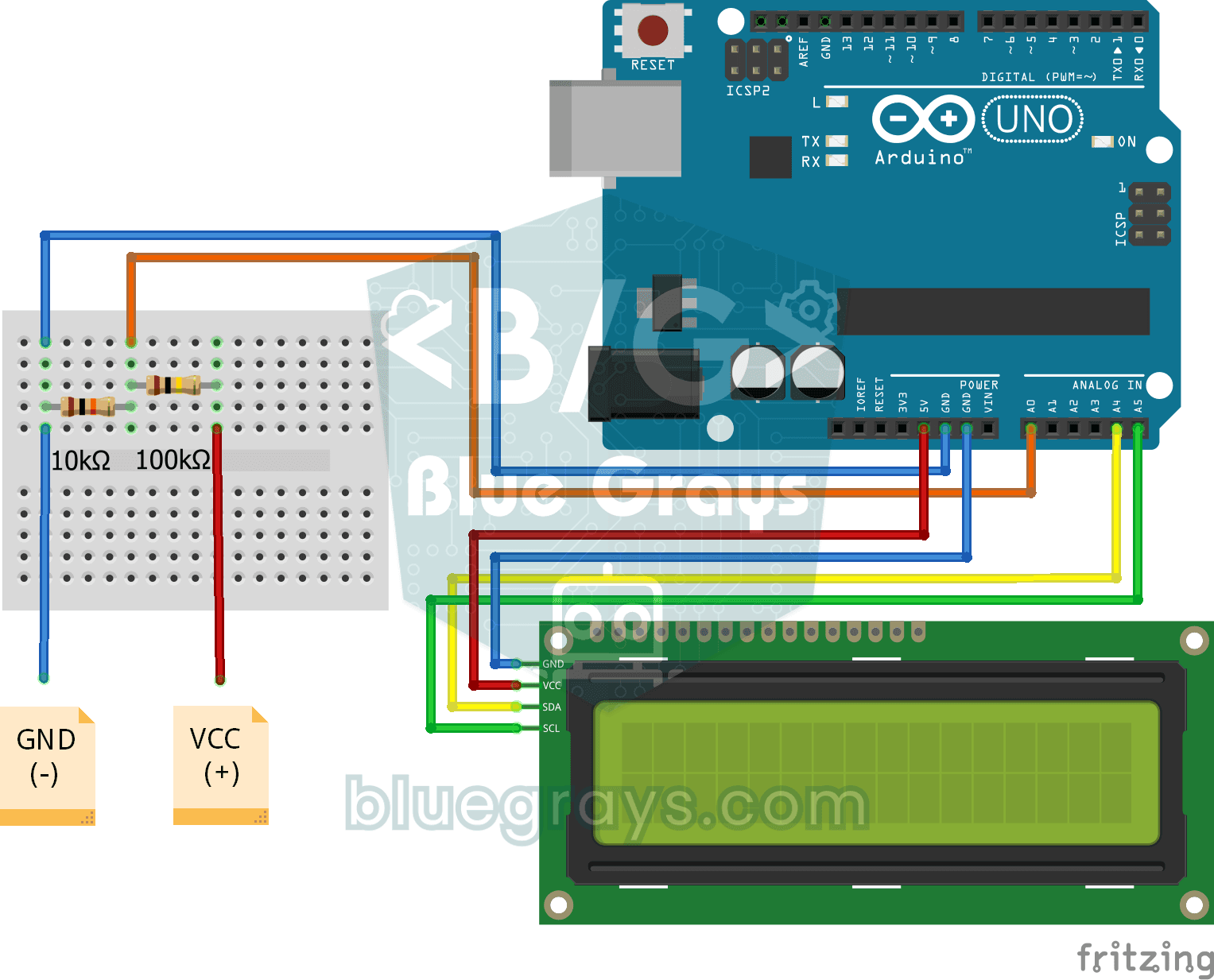
Find out how much voltage a battery or power adapter gives with a meter you built yourself. A divider made of two resistors brings high voltage down to a level the board can read, and the Arduino calc
Using an RGB LED
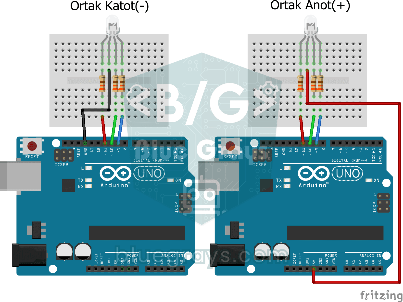
Three colours hide inside a single LED: the RGB LED lights up red, then green, then blue, each colour on for half a second and off for half a second, before the cycle starts again. All you need is one