
Kirchhoff's Laws Explained: KCL and KVL with Solved Examples
Kirchhoff's laws explained: current law (KCL) and voltage law (KVL), nodes, loops and sign rules, 3 solved circuits, checked with Arduino and a multimeter.
Kirchhoff's laws are the two basic rules that describe how currents and voltages are shared in an electric circuit. Kirchhoff's current law (KCL) says: the sum of the currents flowing into a node equals the sum of the currents flowing out of it. Kirchhoff's voltage law (KVL) says: if you go all the way around a closed loop, the signed sum of the voltages you meet is zero. The German physicist Gustav Kirchhoff published these two rules in 1845, while he was still a university student; today every circuit analysis, from a single LED to your phone's motherboard, rests on these two sentences.
Ohm's law gives the relationship between the voltage, current and resistance of a single component; Kirchhoff's laws take into account how those components are connected to each other. Used together, they let you solve circuits with several branches, and even several power sources, with just pen and paper. In this article you'll find the ideas of nodes and loops, the sign convention that confuses people most, three circuits solved step by step, an experiment that verifies the laws by measurement with an Arduino, ESP32 and Raspberry Pi Pico, checks with a multimeter, and the mistakes students make most often.
What are Kirchhoff's laws? Nodes, branches and loops
Before applying Kirchhoff's laws you need to read the circuit correctly, and four ideas are enough for that. A node is a point where three or more components meet; all the legs plugged into the same breadboard row form a single node, because an ideal wire is assumed to have zero resistance. A branch is the path between two nodes that carries one single current; a branch can contain one component or several in series. A loop is a closed path that starts at a node, follows branches and returns to the same node. The smallest loops, which contain no other loop inside them, are called meshes. If you find circuit diagrams hard to read, have a look at How to Read a Circuit Diagram first.
| Term | Definition | Example in an Arduino circuit |
|---|---|---|
| Node | A point where three or more components meet | The midpoint where a voltage divider's two resistors and its load meet (node A in Example 2) |
| Branch | The path between two nodes that carries a single current | The path made of a digital pin, a 220 Ω resistor and an LED |
| Loop | A closed path that returns to the node it started from | 5V → resistor → LED → GND → 5V |
| Mesh | The smallest loop, with no other loop inside it | The ring between two LED branches connected in parallel |
| Reference node | The 0 V point we measure voltages from | The Arduino's GND pin |
Kirchhoff's current law (KCL): current in equals current out
The formula of the current law is ΣI in = ΣI out. You can write the same thing as ΣI = 0 by counting incoming currents as positive and outgoing currents as negative. Behind the law is conservation of charge: electrons can't pile up at a node or appear out of nowhere, so whatever charge flows into a point has to flow out at the same moment. Think of water in pipes: if a pipe carrying 30 litres a minute splits in two and 10 litres flow through one branch, exactly 20 litres must flow through the other. Electricity works the same way: when a 30 mA current splits into two branches and one of them draws 10 mA, the other draws 20 mA.
Let's practise with an example. I1 = 50 mA and I2 = 20 mA flow into a node and I3 = 15 mA flows out; we're looking for the current I4 in a fourth wire and assume it flows out too. By KCL, 50 + 20 = 15 + I4, so I4 = 55 mA. If you had assumed I4 flows into the node, the equation would have been 50 + 20 + I4 = 15, giving I4 = −55 mA. The minus sign isn't a mistake; it simply tells you the current flows opposite to the direction you assumed. You meet this law every day in Arduino projects: the total current leaving the board's 5V pin is the sum of the currents of every sensor, LED and module on that rail. The calculation you do when choosing a power supply is really a KCL calculation.
Kirchhoff's voltage law (KVL): the sum around a closed loop is zero
The formula of the voltage law is ΣV = 0: as you go around a closed loop, the sum of the voltage rises provided by sources equals the sum of the voltage drops across resistors and other components. This follows from conservation of energy. Think of a hike in the mountains: if you climb a hill and come back down by different paths to where you started, your total change in height is zero. In a circuit, the power source lifts the charges to a certain "height" and the resistors and LEDs use it up step by step; when you get back to your starting point, the sum closes at zero.
KVL has two important consequences. First, the voltages of components in series add up to the source voltage: if three resistors in series with a 9 V battery drop 2 V, 3 V and 4 V, their sum is exactly 9 V. Second, all branches connected in parallel between the same two nodes have the same voltage, because two such branches form a loop together and the voltage dropped in one has to equal the voltage dropped in the other. All the rules in Resistors in Series and Parallel are actually special cases of these two laws.
The sign convention: choosing directions and plus or minus
Most mistakes with Kirchhoff's laws come from signs. The rule is simple, but it has to be applied consistently. First, assume a current direction for every branch and mark it with an arrow on the diagram; you don't have to guess the direction correctly. Then choose a direction of travel for each loop (usually clockwise) and, as you go around the loop in that direction, write the voltage of every component you meet according to the table below. The convention we use in this article is: voltage rises are positive, voltage drops are negative.
| Component | Direction of travel | What you write in the KVL equation |
|---|---|---|
| Resistor | Same direction as the assumed current | −I × R (voltage drops) |
| Resistor | Against the assumed current | +I × R (voltage rises) |
| Voltage source (battery, adapter) | From − to + | +V |
| Voltage source (battery, adapter) | From + to − | −V |
| LED or diode (conducting) | From anode to cathode | −Vf (roughly constant drop) |
How to apply Kirchhoff's laws with Ohm's law, step by step
- Draw the circuit; label the nodes with letters (A, B…), name the resistors and sources, and choose GND as the reference node.
- Define a current for every branch (I1, I2, I3…) and show its direction with an arrow.
- If there are n nodes, write the KCL equation for any n − 1 of them.
- If there are b branches, write the KVL equation for b − n + 1 independent loops (usually the meshes).
- Write the resistor voltages as I × R using Ohm's law, so the only unknowns left are the currents.
- Solve the system of equations by substitution or elimination; if you work in kΩ and mA, the results come out directly in volts.
- Check your answer: make sure KVL holds for a loop you didn't use and that the power delivered by the sources equals the power dissipated in the resistors.
Why this number of equations? Each branch current is an unknown, so there are b unknowns. If you write KCL for all n nodes, the last one can be derived from the others, so only n − 1 of them give new information. KVL supplies the remaining b − (n − 1) equations. The nodal analysis and mesh analysis methods you'll meet in class are just organised applications of these two laws: in nodal analysis you write KCL in terms of node voltages, and in mesh analysis you write KVL in terms of mesh currents. The Ohm's law calculator and the series and parallel resistor tool speed up the arithmetic.
Example 1: a series circuit with an LED and a resistor
When an Arduino digital pin is HIGH, it outputs 5 V. We connect a 220 Ω resistor to that pin and a red LED to the other end of the resistor, with the LED's cathode going to GND. The circuit has a single branch and a single loop, so one KVL equation is enough. Let's take the red LED's forward voltage as Vf ≈ 2.0 V. Starting at GND and going around in the direction of the current: the pin gives +5 V, the resistor −220 × I, the LED −2.0 V. The equation is 5 − 220 × I − 2.0 = 0, which gives I = 3.0 / 220 = 13.6 mA. 3.0 V drops across the resistor and 2.0 V across the LED; together they equal the source's 5 V.
| Component | Voltage | Current | Power |
|---|---|---|---|
| Arduino pin (source) | +5.0 V | 13.6 mA | Delivers 68.2 mW |
| 220 Ω resistor | −3.0 V | 13.6 mA | Dissipates 40.9 mW |
| Red LED | −2.0 V | 13.6 mA | Dissipates 27.3 mW |
| Total (KVL and power balance) | 0 V | — | 68.2 = 40.9 + 27.3 mW |
In a real circuit the result is a little different. An Arduino Uno pin's output voltage sags a little as it supplies current; in this circuit the pin drops to around 4.7–4.8 V and the current ends up at about 12.5 mA; the LED's forward voltage also varies with its colour and current. Still, the method is the same: set up the Kirchhoff equation and write the resistor voltage with Ohm's law. We explained in What Is an LED? why an LED has no fixed resistance and should be treated as a roughly constant voltage drop. You can find the right resistor for any colour in seconds with the LED resistor calculator.
Example 2: a voltage divider with parallel branches
Now a slightly more realistic circuit: the 5 V supply first passes through R1 = 1 kΩ and reaches node A. Two branches leave node A: one goes to GND through R2 = 2.2 kΩ, the other through R3 = 3.3 kΩ. This is a voltage divider with a load connected across its bottom resistor. The only unknown node voltage is VA. Let's write KCL at node A: the current coming through R1 equals the sum of the currents going into R2 and R3. Writing the currents in terms of voltage with Ohm's law (in kΩ and mA) gives (5 − VA) / 1 = VA / 2.2 + VA / 3.3. The right-hand side is VA × 0.7576, so the equation becomes 5 = VA × 1.7576 and VA ≈ 2.845 V.
| Quantity | Calculation | Result |
|---|---|---|
| I1 (through R1) | (5 − 2.845) / 1 kΩ | 2.155 mA |
| I2 (through R2) | 2.845 / 2.2 kΩ | 1.293 mA |
| I3 (through R3) | 2.845 / 3.3 kΩ | 0.862 mA |
| KCL check | I2 + I3 | 2.155 mA = I1 |
| Power balance | 5 V × 2.155 mA | 10.78 mW = 4.64 + 3.68 + 2.45 mW |
Now let's check with KVL. Around the left mesh formed by the source, R1 and R2 (5 V → R1 → R2 → GND) we get 5 − 2.155 − 2.845 = 0. In the right mesh formed by R2 and R3, both resistors have the same voltage (2.845 V) and the difference is zero; that's why parallel branches share the same voltage. You can reach the same result with the equivalent resistance: R2 ∥ R3 = 1.32 kΩ, the total is 2.32 kΩ and 5 / 2.32 = 2.155 mA. The practical lesson from this example: before R3 is connected, the divider's output is 5 × 2.2 / 3.2 ≈ 3.44 V; once the load is connected it drops to 2.845 V. The voltage divider formula is only correct when no current is drawn from its output; when you add a load, you have to redo the calculation with KCL. For a quick check you can use the voltage divider calculator.
Example 3: a circuit with two sources and a negative current
The real power of Kirchhoff's laws shows in circuits that can't be solved by series-parallel reduction. On the left, a V1 = 9 V source is connected to a common node A through R1 = 1 kΩ; on the right, a V2 = 5 V source is connected to the same node through R2 = 1 kΩ; from node A, an R3 = 2 kΩ load resistor goes down to GND. The negative terminals of both sources are at GND. Let's assume the currents like this: I1 and I2 flow from the sources towards A, and I3 flows from A to GND. With two nodes (A and GND) and three branches, we'll write 1 KCL and 2 KVL equations (in kΩ and mA):
- KCL (node A): I1 + I2 = I3
- KVL (left mesh): 9 − 1 × I1 − 2 × I3 = 0
- KVL (right mesh): 5 − 1 × I2 − 2 × I3 = 0
Substituting I1 + I2 for I3, the left mesh becomes 3 × I1 + 2 × I2 = 9 and the right mesh 2 × I1 + 3 × I2 = 5. Multiply the first equation by 3 and the second by 2, subtract them and you get 5 × I1 = 17, so I1 = 3.4 mA. Substituting back gives I2 = −0.6 mA and I3 = 2.8 mA. The negative I2 shows that the current doesn't flow from the 5 V source to A but from A into the positive terminal of the 5 V source: the 9 V source is feeding the load and also pushing 0.6 mA into the 5 V source. Let's check with the power balance: V1 delivers 9 × 3.4 = 30.6 mW; R1 dissipates 11.56 mW, R2 0.36 mW and R3 15.68 mW, while V2 absorbs 5 × 0.6 = 3 mW. The total is again 30.6 mW, so the solution is correct. The outer loop we didn't use also works: 9 − 3.4 − 0.6 − 5 = 0.
Verifying Kirchhoff's laws by measurement with an Arduino
To see the theory in an experiment, let's combine a voltage divider and an LED in one circuit. Go from the 5V pin through R1 = 330 Ω to point A. Two branches leave point A: one goes to GND through R2 = 2.2 kΩ, the other goes through R3 = 220 Ω to point B and from there to the anode of a red LED; the LED's cathode connects to GND. The board will read the voltages at points A and B on its analog inputs, calculate each resistor's current with Ohm's law and show whether KCL holds at node A. First, a prediction: treating the LED as a constant 1.9 V drop and writing KCL at node A, the equation (5 − VA) / 330 = VA / 2200 + (VA − 1.9) / 220 gives VA ≈ 2.96 V, I1 ≈ 6.2 mA, I2 ≈ 1.35 mA and I3 ≈ 4.8 mA.
| Circuit point | Arduino Uno | ESP32 | Raspberry Pi Pico |
|---|---|---|---|
| Supply (top end of R1) | 5V | 3V3 | 3V3(OUT), pin 36 |
| Point A (R1, R2, R3 junction) | A0 | GPIO 34 | GP26 (ADC0) |
| Point B (R3 and LED anode) | A1 | GPIO 35 | GP27 (ADC1) |
| Bottom of R2 and LED cathode | GND | GND | GND |
1// Kirchhoff yasalarını ölçerek doğrulama / Verifying Kirchhoff's laws by measurement
2// Besleme -> R1 (330) -> A ; A -> R2 (2.2k) -> GND ; A -> R3 (220) -> B -> LED -> GND
3// Supply -> R1 (330) -> A ; A -> R2 (2.2k) -> GND ; A -> R3 (220) -> B -> LED -> GND
4
5#if defined(ARDUINO_ARCH_ESP32)
6const float VCC = 3.30;          // 3V3 pininde ölçtüğün gerilim / voltage you measured on 3V3
7const int PIN_A = 34;            // ADC1, yalnız giriş / ADC1, input only
8const int PIN_B = 35;
9float readVolts(int pin) {
10  return analogReadMilliVolts(pin) / 1000.0;   // kalibre edilmiş okuma / calibrated reading
11}
12#else
13const float VCC = 5.00;          // 5V pininde ölçtüğün gerilim / voltage you measured on 5V
14const int PIN_A = A0;
15const int PIN_B = A1;
16float readVolts(int pin) {
17  return analogRead(pin) * VCC / 1023.0;       // 10 bit ADC, referans 5V / 5V reference
18}
19#endif
20
21const float R1 = 330.0;          // ohm
22const float R2 = 2200.0;
23const float R3 = 220.0;
24
25float averageVolts(int pin) {    // 16 okumanın ortalaması / average of 16 readings
26  float sum = 0;
27  for (int i = 0; i < 16; i++) {
28    sum += readVolts(pin);
29  }
30  return sum / 16.0;
31}
32
33void setup() {
34  Serial.begin(115200);
35}
36
37void loop() {
38  float vA = averageVolts(PIN_A);
39  float vB = averageVolts(PIN_B);
40
41  float vR1 = VCC - vA;          // R1 gerilimi / voltage across R1
42  float vR2 = vA;                // R2 gerilimi / voltage across R2
43  float vR3 = vA - vB;           // R3 gerilimi / voltage across R3
44  float vLed = vB;               // LED gerilimi / voltage across the LED
45
46  float i1 = vR1 / R1 * 1000.0;  // Ohm kanunu, mA / Ohm's law, mA
47  float i2 = vR2 / R2 * 1000.0;
48  float i3 = vR3 / R3 * 1000.0;
49
50  // KAY: A düğümüne giren = çıkan / KCL: into node A = out of node A
51  Serial.print(F("I1 = "));
52  Serial.print(i1, 2);
53  Serial.print(F(" mA   I2 + I3 = "));
54  Serial.print(i2 + i3, 2);
55  Serial.print(F(" mA   fark / error = "));
56  Serial.print(i1 - i2 - i3, 3);
57  Serial.println(F(" mA"));
58
59  // KGY: dış çevre / KVL: outer loop
60  Serial.print(F("VR1 + VR3 + VLED = "));
61  Serial.print(vR1, 2);
62  Serial.print(F(" + "));
63  Serial.print(vR3, 2);
64  Serial.print(F(" + "));
65  Serial.print(vLed, 2);
66  Serial.print(F(" = "));
67  Serial.print(vR1 + vR3 + vLed, 2);
68  Serial.print(F(" V   kaynak / supply = "));
69  Serial.print(VCC, 2);
70  Serial.println(F(" V"));
71
72  // KGY: paralel kollar aynı gerilimde / KVL: parallel branches share one voltage
73  Serial.print(F("VR2 = "));
74  Serial.print(vR2, 2);
75  Serial.print(F(" V   VR3 + VLED = "));
76  Serial.print(vR3 + vLed, 2);
77  Serial.println(F(" V"));
78  Serial.println();
79  delay(2000);
80}
The code reads each point 16 times and averages the readings, which smooths out small ADC fluctuations. On the Arduino Uno, analogRead() returns a number from 0 to 1023 and its reference is the 5V rail, so one step is about 4.9 mV. In the ESP32 section, the analogReadMilliVolts() function returns the calibrated value directly in millivolts; GPIO 34 and 35 are input-only pins that belong to the ADC1 unit, which keeps working while Wi-Fi is on. Thanks to the #if line, the same code compiles on both boards. With the Serial Monitor set to 115200 baud, on the Uno you'll see a line like "I1 = 6.17 mA I2 + I3 = 6.17 mA". The KCL error is close to zero but not exactly zero; it usually stays below 0.3 mA and comes from the 1–5% tolerance of the resistors and the size of the ADC steps. On the ESP32 at 3.3 V, I1 is about 3.1 mA and the LED glows more dimly.
The same experiment with the Raspberry Pi Pico (MicroPython)
On the Pico, power the circuit from the 3V3(OUT) pin; connect point A to GP26 and point B to GP27. The Pico's ADC returns a value from 0 to 65535 with read_u16() and its reference is about 3.3 V, so multiplying the raw value by 3.3 and dividing by 65535 gives the voltage. At 3.3 V there's less voltage left for the resistors, so the currents are smaller: taking the LED as 1.8 V, expect VA ≈ 2.26 V, I1 ≈ 3.1 mA, I2 ≈ 1.0 mA and I3 ≈ 2.1 mA. If you haven't set up your Pico yet, follow the Thonny steps in What Is the Raspberry Pi Pico?.
1from machine import ADC, Pin
2import time
3
4VCC = 3.3                          # 3V3(OUT) pininde ölçtüğün gerilim / voltage you measured on 3V3(OUT)
5R1, R2, R3 = 330, 2200, 220        # ohm
6adc_a = ADC(Pin(26))               # GP26 = ADC0, A noktası / node A
7adc_b = ADC(Pin(27))               # GP27 = ADC1, B noktası / node B
8
9def volts(adc):
10    total = 0
11    for _ in range(16):            # 16 okumanın ortalaması / average of 16 readings
12        total += adc.read_u16()
13    return total / 16 * VCC / 65535
14
15while True:
16    v_a = volts(adc_a)
17    v_b = volts(adc_b)
18    i1 = (VCC - v_a) / R1 * 1000   # Ohm kanunu, mA / Ohm's law, mA
19    i2 = v_a / R2 * 1000
20    i3 = (v_a - v_b) / R3 * 1000
21    # KAY: A düğümüne giren = çıkan / KCL: into node A = out of node A
22    print("I1 = {:.2f} mA  I2 + I3 = {:.2f} mA  fark / error = {:.3f} mA".format(i1, i2 + i3, i1 - i2 - i3))
23    print("VR1 = {:.2f} V  VR2 = {:.2f} V  VR3 = {:.2f} V  VLED = {:.2f} V".format(VCC - v_a, v_a, v_a - v_b, v_b))
24    time.sleep(2)
Checking the laws experimentally with a multimeter

A multimeter lets you see Kirchhoff's laws by direct measurement, without writing any code. For KVL, turn the selector to DC voltage (DCV); measure the source voltage first, then the voltage of each component in the loop one by one. If you always put the red probe on the end that comes first in your direction of travel and the black probe on the next one, the signs come out right automatically. For KCL you need to open the circuit: plug the red lead into the mA socket, disconnect the branch you want to measure at one point and connect the multimeter in series across the gap. A more practical way is to measure a resistor's voltage and divide by its value to get the current; that way you never open the circuit. We explained the ranges and the fuse in detail in How to Use a Multimeter.
| Measurement | Where the probes go | Expected (at 5.00 V) |
|---|---|---|
| Source | 5V and GND | 5.00 V |
| V_R1 | 5V and point A | ≈ 2.04 V |
| V_R2 | Point A and GND | ≈ 2.96 V |
| V_R3 | Points A and B | ≈ 1.06 V |
| V_LED | Point B and GND | ≈ 1.90 V |
| KVL check | V_R1 + V_R3 + V_LED | 2.04 + 1.06 + 1.90 = 5.00 V |
| KCL check (mA range) | I1 vs I2 + I3 | ≈ 6.18 mA = 1.35 + 4.83 mA |
Don't expect your measurements to match the calculation exactly; differences of 2–5% are normal. There are four reasons: the tolerance of the resistors (5% for gold-band resistors, 1% for brown-band ones), the accuracy of the multimeter itself (around 0.5% plus a few digits on DC voltage for budget models), the internal resistance of the meter on the mA range (from a few ohms up to 10 Ω; since it's in series with the branch, it slightly reduces the current) and the LED's forward voltage changing with temperature. On the voltage range the meter's input resistance is usually 10 MΩ, so its effect on kΩ circuits is negligible. If the difference exceeds 10%, a resistor's value may have been misread, a connection may be loose or breadboard rows may be mixed up; check against the internal wiring diagram in What Is a Breadboard?.
Where are Kirchhoff's laws useful? Project ideas
- Power budget: add up the current of every module in your project (KCL) and check whether the adapter or battery can supply it; use the battery life calculator to estimate running time.
- Arduino voltmeter: build a voltage divider that measures 0–25 V and account for the load of the analog input with KCL; the steps are in Building an Arduino Voltmeter.
- Multi-LED panel: give each LED its own resistor, calculate the total current and check that it stays within the pin and regulator limits.
- LDR light meter: an LDR and a fixed resistor form a voltage divider; work back from the measured voltage to the LDR's resistance with KVL (LDR light sensor).
- Wheatstone bridge: in a four-resistor bridge, the voltage between the two midpoints is zero when R1 / R2 = R3 / R4; load cells work on this principle (HX711 load cell).
- Measuring current with a shunt resistor: put a small resistor such as 1 Ω in the load line, measure the voltage across it and find the circuit's current with I = V / R; for larger currents an ACS712 current sensor is a better fit.
Common student mistakes and how to fix them
- Changing the sign convention halfway around a loop: writing one drop as negative and another as positive breaks the equation. Choose the direction of travel at the start and stick to the rule in the table.
- Thinking a negative current is a mistake: a current that comes out negative is simply flowing the other way. There's no need to solve the circuit again; use the value with its sign.
- Writing too many or duplicate equations: writing KCL for all n nodes doesn't add an independent equation. Stick to n − 1 KCL and b − n + 1 KVL equations, and don't write the same loop twice.
- Mixing up units: multiplying ohms by milliamps gives millivolts, not volts. Write everything either in V, A and Ω or in V, mA and kΩ.
- Treating an LED like a resistor: an LED has no fixed resistance; when conducting, it behaves like a roughly constant voltage drop (1.8–2.2 V for red). Write it as −Vf in KVL.
- Assuming the source is ideal: USB 5 V is usually somewhere between 4.75 and 5.25 V, and a battery has internal resistance. Use the value you measured instead of 5 V in your calculations.
- Forgetting the common ground: if the GNDs of two circuits powered by different sources aren't connected, there's no shared reference between them and the measurements are meaningless. Details are in GND and Common Ground.
- Connecting the ammeter in parallel or the voltmeter in series: current is always measured in series by opening the circuit, and voltage always in parallel across the component.
Kirchhoff's laws are just two sentences, yet they sit underneath everything you calculate in electronics: current doesn't vanish at a node, and voltages sum to zero around a loop. Used together with Ohm's law, they let you work through any question step by step, from LED resistors and loaded voltage dividers to circuits with two sources and power budgets. If you want to try what you've learned on a real circuit, take a look at the LED, LDR light measurement and LCD digital voltmeter projects in the BlueGrays app; each one walks you through the circuit diagram and the code step by step, so you can keep your multimeter next to you and compare your readings with the calculations here.
Frequently asked questions
What is Kirchhoff's current law?
Kirchhoff's current law (KCL) states that the sum of the currents flowing into a node equals the sum of the currents flowing out of it. It's based on conservation of charge: charge can't pile up or disappear at a point. For example, if a 30 mA current splits into two branches and one draws 10 mA, the other draws 20 mA.
What is Kirchhoff's voltage law?
Kirchhoff's voltage law (KVL) states that the signed sum of the voltages around any closed loop is zero. In other words, the voltage supplied by the source equals the sum of the voltage drops across the components in that loop. In a 5 V circuit, if the resistor drops 3 V, 2 V is left for the LED.
What is the difference between Kirchhoff's laws and Ohm's law?
Ohm's law (V = I × R) describes the relationship between the voltage, current and resistance of a single resistor. Kirchhoff's laws describe how components are connected: how currents split at nodes and how voltages add up around loops. To solve a circuit you use both: you set up Kirchhoff's equations and write the resistor voltages with Ohm's law.
What does a negative current mean in Kirchhoff's laws?
A negative current doesn't mean your solution is wrong; it means the current flows opposite to the direction you assumed at the start. Its magnitude is correct, so you only need to flip the arrow on the diagram. You can keep using the value with its sign in other calculations without solving the circuit again.
How many equations do I need with Kirchhoff's laws?
If a circuit has b branches and n nodes, there are b unknown currents. You write the current law for n − 1 nodes and the voltage law for b − n + 1 independent loops, so the number of equations equals the number of unknowns. For example, a circuit with 3 branches and 2 nodes needs 1 KCL and 2 KVL equations.
Do Kirchhoff's laws apply to AC circuits?
Yes, they always apply to instantaneous values. However, in AC circuits with capacitors and inductors you can't simply add RMS voltages; you have to add them with their phases, using phasors or complex numbers. At very high frequencies and on long transmission lines, the simple form of the laws gives way to wave models.
Projects to build after reading this
See all projects
Two LEDs Blinking Alternately
Two LEDs blink quickly in turn: when one lights up the other goes off, as if they were tossing a ball back and forth. The Arduino keeps each light on for a fifth of a second and then hands over to the

LED Blink
The very first hello of electronics: switching a single LED on and off. The Arduino turns the LED on and off at short intervals, so the light blinks quickly. You see in the simplest way how the board

Measuring Light Intensity with an LDR
Want to see how bright your room is as a number? The LDR, a small part that reacts to light, measures the light around it, and the Arduino writes the value to your computer screen every half second. C

Night Light with Ldr
A little night light that turns on by itself when it gets dark and goes off when morning comes. A light sensor measures how bright the room is, and the Arduino switches the LED on when it is dark enou

Reading Light Intensity with the ESP32 LDR Module
Real-time monitoring of the LDR module's raw ADC value and relative light percentage calculated from dark and light reference values in the Serial Monitor. This percentage is not a lux measurement. Teaches the module’s calibration logic. It is ideal to complete this before Project 10, as it is used to determine the threshold value.
Raspberry Pi Pico: Controlling an External LED (Breadboard)
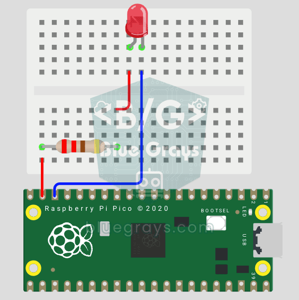
The next step after Pico’s built-in LED: connecting an external LED to the breadboard and controlling it via the GP14 pin. In this project, you’ll learn how to use any of the Pico’s general-purpose GPIO pins as an output, the LED’s polarity (long leg = anode/+, short leg = cathode/–), and why a current-limiting resistor (220Ω) is required. If you don’t include the resistor, excessive current will flow through the LED and it may burn out. The circuit is very simple: Pico GP14 → 220Ω resistor → LE
Digital Voltmeter with LCD Display
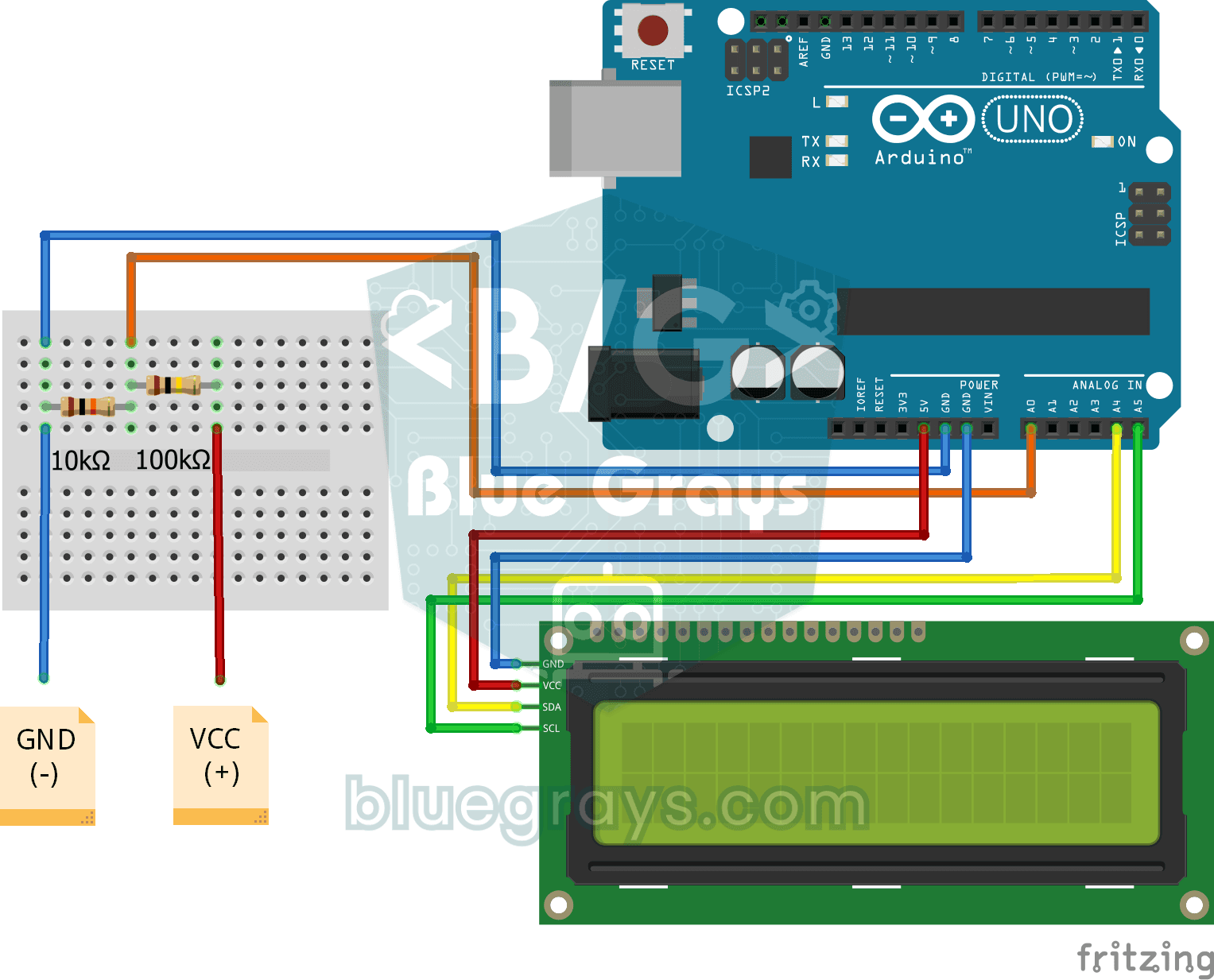
Find out how much voltage a battery or power adapter gives with a meter you built yourself. A divider made of two resistors brings high voltage down to a level the board can read, and the Arduino calc

ESP32 LED Brightness Control with a Potentiometer (Analog → PWM)
In this project, we control the brightness of an LED analogically using a potentiometer. The ESP32's ADC pin reads the 0-3.3V voltage from the potentiometer, and this value is then converted into a PWM (Pulse Width Modulation) signal and sent to the LED. As a result, as you turn the potentiometer, the LED gradually brightens and dims. With Arduino Core 3.0+, analogWrite() can be used directly; on the ESP32-S2/S3, the ADC resolution is fixed at 12-bit.